Page 1.2 SWITCHING MATRIX MODULE 20-517A/518A
pickering
SECTION 1 - TECHNICAL SPECIFICATION
Switching Matrix Module – 20-518A
pickeringtest.com
Specifications
Switching Specification
Max Voltage:
Max Power:
Max Switch Current:
Max Carry Current:
100V DC
20W
0.5A
1.2A
On Path Resistance:
Off Path Resistance:
Differential Thermal Offset:
<500mΩ
>108Ω
<20µV
Capacitance
Open Channel to Ground:
Selected Channel to Ground:
Open Input to Ground:
<40pF
<70pF
<4pF
Bandwidth:
Isolation (at 1MHz):
Crosstalk (at 1MHz):
5MHz
>55dB
>55dB
Switching Time: 15ms
Expected Life (Low power):
Expected Life (Full power):
>1x10⁸ operations
>5x10⁶ operations
Safety & CE Compliance
All modules are fully CE compliant and meet applicable EU
directives: Low-voltage safety EN61010-1:2010, EMC Immunity
EN61326-1:2013, Emissions EN55011:2009+A1:2010.
Operating/Storage Conditions
Operating Conditions
Operating Temperature:
Humidity:
Altitude:
0°C to +55°C
Up to 95% non-condensing
5000m
Storage and Transport Conditions
Storage Temperature:
Humidity:
Altitude:
-20°C to +75°C
Up to 95% non-condensing
15000m
Programming
The matrix module is very easy to program using the Intelligent
IEEE-488.2 Interface:
ARESET a Open all switches on device a
DIAGNOSTIC? Report any Self Test errors
DELAY t Force a minimum delay of tmilliseconds
between two instructions
MCLOSE a,x,y Close switch at coordinates x,y on matrix
a
MOPEN a,x,y Open switch at coordinates x,y on matrix
a
RESET Open all switches on all modules
VIEW? a View status of device a
Further matrix control may be achieved using the IEEE-488.2
stored settings commands (*SAV/*RCL), these permit the
storage and later recall of complex matrix congurations.
Reed Switch Type
Ruthenium Electro-Plated Reed Relays offer maximum
performance, they are hermetically sealed and offer a very stable,
long life relay contact (over 108 operations) with fast operate time.
Alternative types such as electro-mechanical armature relays are
lower cost but do not offer the consistent contact resistance, long
life, fast switching speed and low level switching capability of a
Ruthenium reed relay.
All reed relays are manufactured by our sister company Pickering
Electronics: pickeringrelay.com
Connectors
Matrix connection is via a high quality 96-Pin Rectangular
Multipole
Connector (ZIF type), this is pin compatible
with appropriate
modules in the 20-510A & 20-515A range.
Mechanical Characteristics
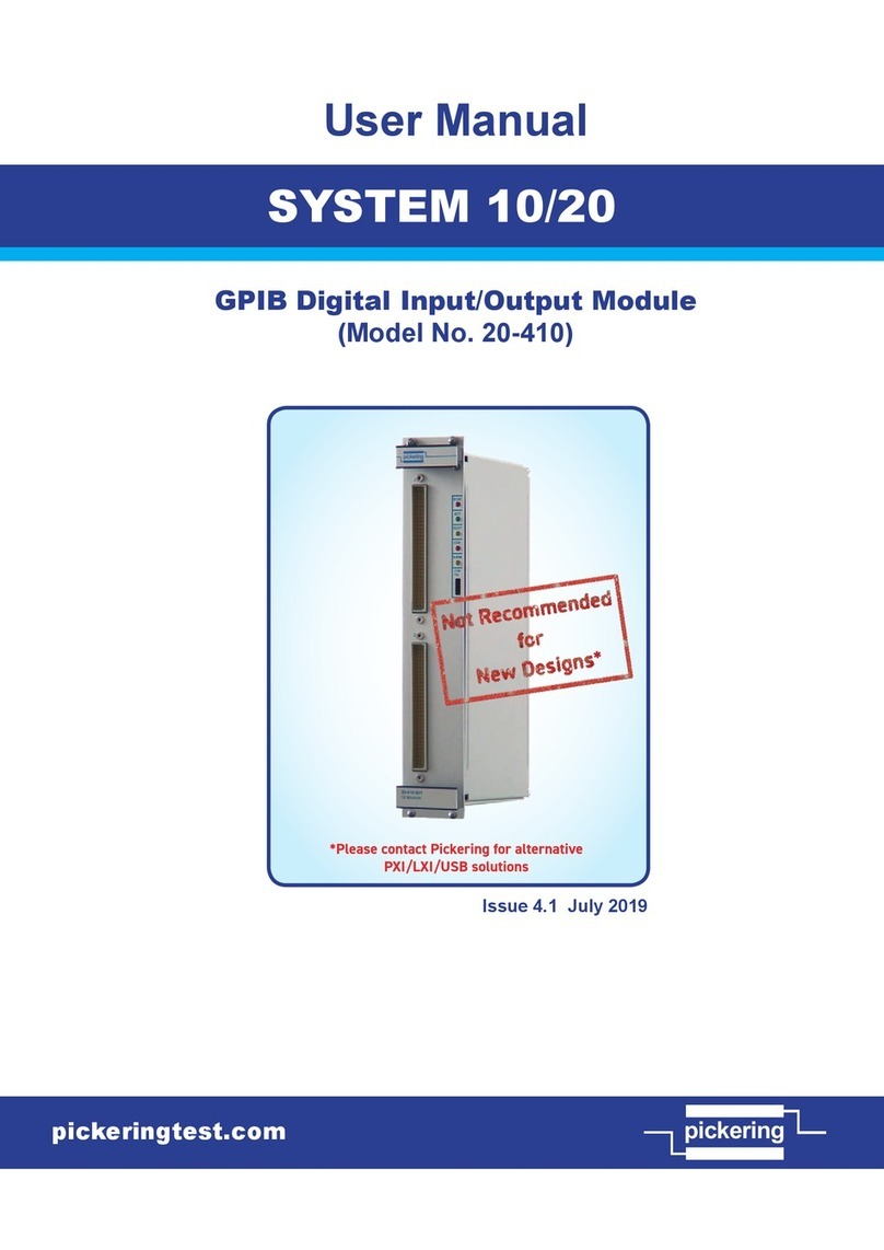
All 20-518A model versions are housed in a shielded 6U height
(262mm) Eurocard module and are 160mm deep. Panel width for
all versions is 1.8 Inches.
Self Test Details
Self-Test is invoked at power on (taking up to 60 seconds) and
may also be operated under software (*TST?) or via a recessed
push button. Self-Test pass is indicated on a front panel LED with
a full pass/fail description available using the DIAGNOSTIC?
command. Self-Test comprises 3 levels:-
1. Logic Test
2. Relay Coil Test
3. Full Contact Test
Mixed Matrix/Multiplexers Configurations
For some users requiring very large matrix systems the cost of a
“full” matrix may prove prohibitive, in many instances a combination
of multiplexer input/output and partially lled matrix may prove quite
acceptable and could prove to be more effective in terms of both
cost and performance. Please contact Pickering to discuss your
application in detail.

