PICOTE MINI PUMP Use and care manual

1
These instrucons are for your personal safety. Always ensure that you have
read and understood these instrucons before using any of the Picote Brush
Coang ™ System Range.
PICOTE BRUSH
COATING™
SYSTEM
MINI PUMP
OPERATION
& SAFETY
MANUAL

2
Table of Contents
3
4
5
5
6
7
8-9
SAFETY INFORMATION & SYMBOLS
ENVIRONMENTAL, TRANSPORT, STORAGE &
DISPOSAL
CE DECLARATION OF CONFORMITY
WRC PRODUCT CERTIFICATE
PICOTE MINI MILLER COATING PUMP
MINI MILLER
REQUIRED PARTS
PREPARING THE ORIGINAL PIPE FOR COATING
COATING SYSTEM ASSEMBLY
THE PUMP
THE BRUSHES
DELIVERY HOSE & CAMERA
PREPARING THE RESIN
OPERATING THE COATING SYSTEM
CLEANING UP THE COATING SYSTEM
CURING & ADDITIONAL COATS
PICOTE EPOXY RESIN INFORMATION
MAINTENANCE
ERROR CODE LIST
WARRANTY POLICY & PROCEDURE
Topic Page
To watch praccal demonstraon videos, or to download an electronic copy of these
Instrucons, please visit www.picotesoluons.com. Please note that videos are not
intended as a replacement or alternave to this operang and safety manual, but
only as an addional learning tool.
10-11
12-16
17-19
20-23
24-27
28-31
32-36
37
38
39-41
41
42

3
Safety Information & Symbols
WARNING
!This secon contains important safety informaon.
Failure to comply could result in serious injury or death.
Safety Symbols
DANGER
Risk of serious injury,
follow instrucons
DANGER
Risk of serious injury
from rotang parts
DANGER
Risk of serious injury
from electric shock
Personal Protective Equipment PPE
Always use Personal Protecve Equipment when using the Picote Coang System, including suitable
overalls / protecve clothing & footwear and the following:
Always wear suitable eye protecon when using the Coang System to pre-
vent coang resin or other dust from irritang your eyes.
Always wear suitable ear protecon when using the Coang System to prevent
any hearing loss.
Always wear suitable resin-resistant gloves when using the Coang System to
prevent any skin irritaons. Any open injuries or skin irritaons should be covered
at all mes to avoid contact with resin or dust.
Always wear a suitable venlaon mask when using the Coang System to prevent
any resin dust or vapors being inhaled or consumed, which can cause occupaonal
asthma or resin dermas as well as eye irritaon.
Always Remember
Always ensure that the machine is fully turned o and unplugged before inspecon,
maintenance, or installing any accessories to the machine. Failure to comply may lead to
serious injury including electric shock.
Dust produced when working can be dangerous to your health, inammable or explosive.
Make sure the drain pipe has been opened and venlated to stop any gases forming in the
lateral drain where the work takes place.
Before assembly, use, replacement of parts or maintenance, unplug the Picote milling
machine from its power socket. Failure to comply may lead to serious injury including injury
from rotang parts.

4
ENVIRONMENTAL, TRANSPORT, STORAGE & DISPOSAL
WARNING
!This secon contains important safety informaon.
Failure to comply could result in serious injury or death.
TRANSPORT
Mini Coang Pump should be transported in car or other vehicle laid down and secured with ratchet straps to
prevent any sudden movements or accidents caused by hard braking or accident.
Never transport the pump unit locked on top of the Picote milling machine. In a case of accident, the locking
system may fail.
If using pick-up or trailor to transport Picote Mini Coang Pump, cover the unit to protect it from raining wa-
ter and dust.
STORAGE
Mini Coang Pump should be stored under cover in between +10 oC to +40 oC (50 oF to 104 oF). It is recem-
mended that the coang pumps are stored indoors protected from rain and sunlight and in constant tempe-
rature. Best way to store the machines is in the same box that the machine has been originally shipped.
If Mini Coang Pump will be stored in colder environment than +10 oC (50 oF ), the pump should be stood at
room temperature for 24hours before use.
If Mini Coang Pump has been stored for long periods of me (over 2-3 months), it should be checked and
tested according to maintence program before use.
DISPOSAL
Mini Coang Pump motor, control box, pumping assembly and electric wires can be disposed in Europe at
Waste Electrical and Electronic Equipment (WEEE) collecon points. Pump frame can be recycled in metal
waste collecon points.
Dispose unused coang resin according to local waste regulaon. Safest way to dispose the product is to mix
the product in well venlated locaon while using nonammable container. Mixed product will generate
heat while hardening. Follow instrucons of MSDS.
Always follow the local waste handling rules and regulaon.
ENVIRONMENTAL
Operaonal Ambient Temperature Range: -10...50 oC (14...122 oF) frost and condensaon free
Storage Ambient Temperature Range: -20...60 oC (-4...140 oF) frost and condensaon free
Maximum Altude: 2000m (6500 ). Derate above 1000m: 1% / 100m
Maximum Humidity: 95% non-condensing

5
We Picote Soluons Oy Ltd as the responsible manufacturer, declare that the following Picote Soluons Oy Ltd
machine:
Mini Coang Pump
is of series producon and
Conforms to the following EU Direcve:
2006/42/EC
And is manufactured in accordance with the following standards or standardised documents:
EN 809 + A1/AC, EN 60204-1:2018
The technical documentaon is kept by our authorised representave in Europe who is:
Picote Soluons Oy Ltd, Pienteollisuuse 24
06450 Porvoo, Finland
1st January 2017
Katja Lindy-Wilkinson
C.E.O.
Picote Soluons Oy Ltd
Pienteollisuuse 24, 06450 Porvoo, Finland
Picote Brush Coang SystemTM has been granted with WRc Product Cercate for non-potable and
waste water applicaon for pipe diameters DN32 (11/4”) to DN300 (12”).
Cercate Number: PT/431/0918
Issued: September 2018
Expiry: March 2020
Product Cercate and Assessment Schedule can be downloaded from picotebrushcoang.com.
WRc APPROVED CERTIFICATE
CE Declaration of Conformity

6
Picote Mini Miller Coating Pump
Intended Use
Power Cord
Resin Supply Hose
Delivery Hose
Motor
Resin Cup Locaon
Speed Control
Reverse/Forward
On/O Buon
Release, locks pump to Miller
Resin Release Buon
Smart Mixer Plaorm
1.
2.
3.
4.
5.
6.
7.
8.
9.
10.
11.
General Descripon This machine is intended for the following uses:
1. Coang pipes from DN32-200 / 1.1/4’’- 8’’
2. Cleaning sewers and drains with degreaser.
Always follow the manufacture’s instrucons when
installing and using the machine with accessories.
SIZE HOSE RANGE ROTATING SPEED OUTPUT (kw) POWER SOURCE WEIGHT
41x42x54.4 cm 8/10mm Max 22m Depends on pipe diameter 0.18 110v or 230v 16kg
16.2.2x16.5x21.5’’ Max 75 35.5 lb
Ensure that the supply voltage is correct. The voltage of the power source must
match the value given on the nameplate of the machine. Available in 230v and
110v.
The machine should be connected only to a power supply of the same voltage
as indicated on the nameplate, and can only be operated on single-phase AC
supply.
This machine has a hand-held locking operator control boom or “LOC”. When
the control buon is pushed the pump is engaged and will operate unl de-
pressed.
1
2
34
5
6
7
8
9
10
11
Voltage
Power Supply

7
Mini Miller 8/17 WARNING
!
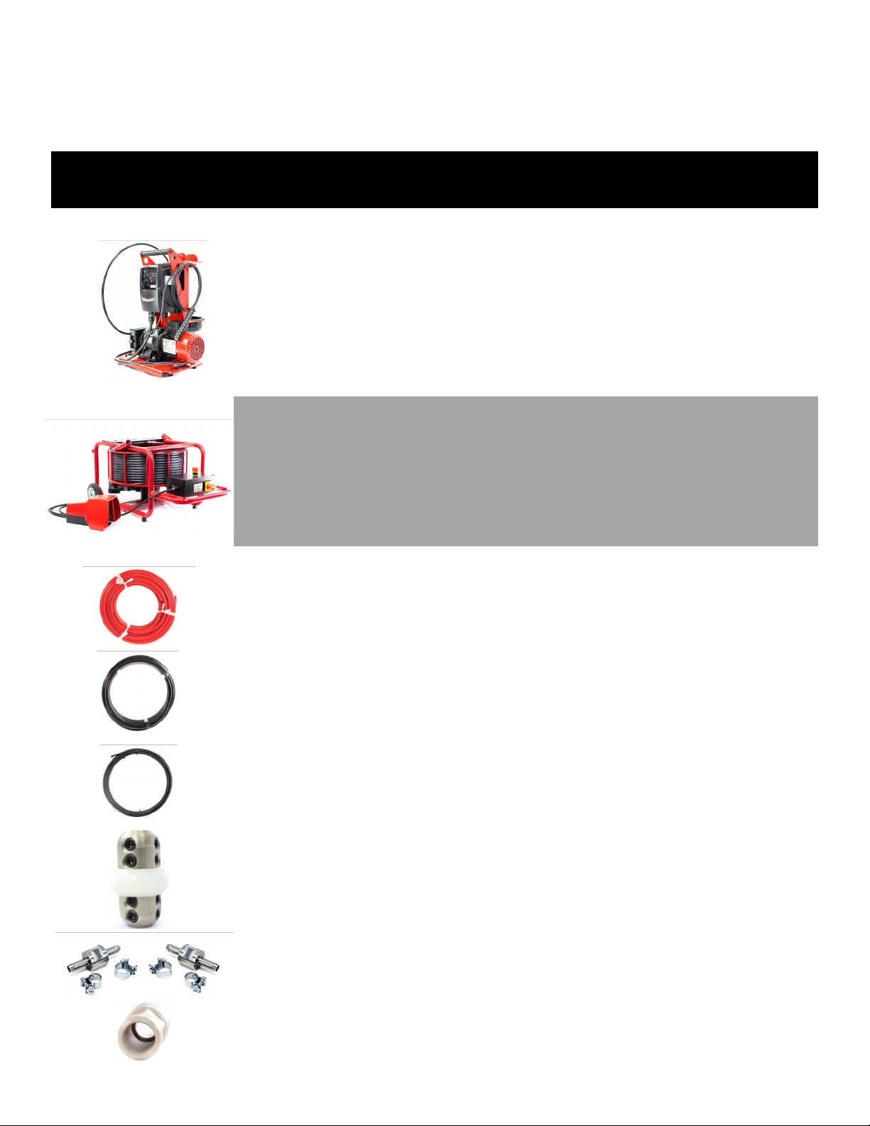
The Mini Miller powers the Mini Coang Pump
Note: can also be used with the Micro Miller
Please refer to the Mini Miller manual
for more informaon
General Descripon
Cable Rack
Frame
Flexible Sha
Motor & Bevel Gear (not shown)
Emergency Stop Boom (red)
Power Switch
Speed Control
Foot Pedal—Operator Presence Control
Hand Guard & Strain Relief/inside Hand
Guard (not seen in photo)
1.
2.
3.
4.
5.
6.
7.
8.
9.
Intended Use
This machine is intended for the following uses:
1. Coang pipes from DN32-200 / 1.1/4’’- 8’’
2. Cleaning sewers, drains and pipes by grinding.
(Picote Grinding Chains)
3. Reinstang branches in sewers and drains by
drilling and grinding. (Picote Lateral Cuer)
Always follow the manufacture’s instrucons when
installing and using the machine with accessories.
SIZE SHAFT RANGE ROTATING SPEED OUTPUT (kW) POWER SOURCE WEIGHT
752x519x389 8mm 17m 500-2900rpm 110V:1.1kW 110v or 230v 27kg
29.6x20x15.3’’ 1/3’’ 55 230V:1.2kW 59.5lb
When is use, always lay the machine down horizontally on the oor as shown above. When not in use, some
non-hazardous Picote Flexible Sha Lubricant might leak from the hand guard.
1
2
3
4
5
6
9
8
7
VOLTAGE
Ensure that the supply voltage is correct. The volt-
age of the power source must match the value giv-
en on the nameplate of the machine.
FOOT PEDAL
The machine has an operator presence control
or ‘OPC’. When the control is not held down,
the machine stops.
POWER SUPPLY
The machine should be connected only to a power supply
of the same voltage as indicated on the nameplate, and
can only be operated on single-phase AC supply.
EMERGENCY STOP
There is an Emergency Stop Buon on the machine. The pow-
er supply to the motor is cut o when the Emergency Stop
Buon is pushed. Always make sure the Emergency stop
Buon is pressed and completely unplug the machine when
the machine accessories (e.g. Cuer or Grinding Chains) are
not inside the pipe.

8
Required Parts
First make sure you have all the required parts.
PRODUCT NAME
PRODUCT NUMBER
DESCRIPTION
INFORMATION
1. MINI MILLER COATING
PUMP
2220100001
2220100002
Mini Miller Coang Pump
EU 230v
Mini Miller Coang Pump UK,
US 110v
Hoses, brushes & other parts
sold separately
2. MINI MILLER
3540000817
354000817UK
3540000817US
Mini Miller 230v, 17m range
Mini Miller 110v, 17m range
Mini Miller 110v, 55 range
8mm / ⅓’’ Sha
3. HOSES & SHAFT
2220100004
2220100003
1312030085017
9123050001
2220100007
93212321085
Resin Supply Hose
Resin Delivery Hose
Mni Miller spare sha, 8mm
with thick outer casing
Sha connector
Hose Connector with two hose
clamps (11 & 13mm)
Sleeve 2 Plasc for 8mm thick
casing
Supplied in 25m/82 lengths.
Color-Red
Supplied in 25m/82 lengths.
Color-Black
17.5 meters/57.4
Necessary if aaching a sha
extension

9
Required Parts
First make sure you have all the required parts.
PRODUCT NAME
PRODUCT NUMBER
DESCRIPTION
INFORMATION
4. COATING BRUSHES &
BRUSH STOPPER
2120000050
2120000075
2120000100
2120000125
2120000175
2120000220
900000338
For DN32/ 1.¼’’ drain
For DN50/2’’ drain
For DN70/3’’ drain
For DN100/4’’ drain
For DN150/6’’ drain
For DN200/8’’ drain
Brush Stopper
6mm/ ¼’’ sha
DN50/2’’ - DN200/8’’ t
8mm/⅓’’ sha only
Extra stopper to secure brush
5. PICOTE 100% SOLIDS EPOXY 2110001001
2130000002
2130000001
2110001003
Picote Dual Color Epoxy Kit,
12lbs 5oz
Nut (pack of 10)
Tip (pack of 10)
Special Lubricant designed to
reduce fricon
6 Cartridge Kit (3 White, 3
Dark Grey) with 8 Tips & 3
Nuts.
More informaon on p.37
1 quart hose lubricant
6. PICOTE SMART MIXER 2130001001 Picote Smart Mixer Baery powered cartridge
case with spare baery,
charger and addional 600ml
piston. Please see the Smart
Mixer operang manual for
more informaon.
7. DRAIN CAMERA Use your own mini camera Mini camera is necessary for
the process as a standard cam
will weight the rush down too
much and create problems
with the nished product.
8. OTHER ITEMS Duct Tape
Resin Cups
Acetone, Rags & Bucket
Latex/Nitrile Gloves
Razor Knife
Scissors
7mm Nut Driver for Hose
Clamps
2.5mm Hex Key for Scews
Spare Hose Clamps
Be sure you have plenty of
rags for the clean-up pro-
cess.

10
PREPARING THE ORIGINAL PIPE
FOR CLEANING
Substrate preparaon is one of the most crucial steps in the coang process as specialized coang resin is
designed to bond to the host pipe. Be sure to remove all scale, grease, dust and any other debris com-
pletely from the pipe before coang. If coang plasc pipe be sure to abrade thoroughly with Picote
Smart CuerTM grinding panels.
WARNING
!
STEP 1 Clean the host pipe very well. Use Original (a) or Cyclone (b) grinding chains with carbides
for cast iron pipes and ush with water. For PVC pipes, use the special PVC chains (c). Use
a wire brush (d) to remove nal dust and other remaining parcles.
OPTIONAL STEP: For pipe with excessive build-up of fats, oils or grease (FOG) a degreaser may be
necessary. This can be pumped into the pipe during cleaning if necessary using the coang pump system and
Eco-friendly degreasing agent.
A. B. C. D.

11
Preparing The Original Pipe For Coating
STEP 2
STEP 3
When necessary, run the Smart Cuer with side grinding
panels through the pipe to create a rough surface and
allow for the resin to have the best possible bond to the
pipe wall.
The pipe MUST be dry before connuing with the coang setup. Use the Picote
Heater to expedite the process.
Once the original pipe is clean, move on to the
Coating System Pump Assembly

12
COATING SYSTEM ASSEMBLY
>THE PUMP
Required Tools & Parts
SCISSORS
NUT DRIVER 7mm
PICOTE HOSE LUBE
RESIN CUP
RED SUPPLY HOSE
BLACK DELIVERY HOSE
11mm & 13mm HOSE CLAMPS
BEFORE BEGINNING ASSEMBLY
DANGER
Risk of serious injury from rotating parts!
• Have plenty of rubber gloves and towels available. Wearing a double layer of rubber
gloves is useful when applying lubricant.
• Be sure that all machines have the required power supply.
• Test machines and power source to ensure adequate and safe operaon.

13
Coating System Assembly
>The Pump
STEP 1
STEP 2
STEP 3
Cut the Resin Pump Supply Hose in between 248mm to 254mm (9.¾” to 10”). Ensure
the ends are squared.
Prepare the Hose Connectors and Hose Clamps to be inserted into Resin Supply
Hose. There are 2 small hose clamps for black hose (10mm) and 2 larger hose clamps
for red hose (13mm).
Insert hose connectors and rotate notched surface up while following the natural curve
of the hose. Ensure hose clamps are facing outward and inward. Once posioned
properly ghten the hose clamps. This is important when installing into the pump
housing.
248mm to 254mm / 9.¾” to 10”

14
Coating System Assembly
>The Pump
STEP 4
STEP 5
STEP 6
With hose clamps facing outward, insert the connector into boom of the housing
key-way.
Push hose into housing and slowly rotate the pump rotor clockwise manually while
feeding the hose into place. Tip! Silicone grease will make the process easier.
Slide second connector into the top key-way.
Note: light pressure will be needed to pull the top connector into the key-way.

15
STEP 7
Coating System Assembly
>The Pump
Ensure hose clamps are facing inward and outward for easy access if required.
STEP 8 Apply a small amount of a silicone grease to the underside of the hose at the boom of
the housing. This allows the hose to always return to the center aer the rollers pass
over it.
STEP 9 Close housing door to secure connectors. Pump door should remain closed at all mes
during the coang process.

16
STEP 12
STEP 11
STEP 10
Coating System Assembly
>The Pump
Cut a 1.2m or 47” piece of the black Delivery Hose to be used as a supply hose
extension. One end will require a 45 degree angle and the other should be a square cut.
Aach the square end of the hose to the top hose connector on pump using a small
hose clamp.
Take the 45 degree end and place in the resin cup at the back of the pump. Run the
hose through the retaining holes on the back of the pump.

17
COATING SYSTEM ASSEMBLY
>Brushes
Required Tools & Parts
BRUSHES (1 or 2)
BRUSH STOPPER
SLEEVE BEARING
ALLEN KEY (2.5)
ADJUSTABLE WRENCH
Before Beginning Assembly
• Have extra brush stoppers and hose
connectors available.
• Use angle grinder or portable band saw
to cut Mini Miller sha if necessary.
• Have a roll of duct tape available.

18
Coating System Assembly
>Brushes
STEP 1
STEP 2
** The Mini Coang Pump can be used in DN200/8’’ drain if it is 10m/32’
or less. If coang >8’’ pipes use the Maxi Coang Pump.
Select the appropriate brush size for the pipe. Always use a brush one pipe size larger
than the pipe to be coated.
Note: Although one brush can be used in straight pipe, dual brushes are required for
pipes with bends or transions.
Always use a sleeve on the outer casing of the miller sha. Aach the smaller brush
against the sleeve leaving roughly 6mm / 1/4” between the brush hub and sleeve and
secure the two 2.5mm set screws. DO NOT OVER TIGHTEN OR SCREWS MAY STRIP THE
NYLON HUB.
Recommended Coating Brush Diameters
Host Pipe Diameter Front Coating Brush
Diameter (Straight) Front Coating Brush
Diameter (Multiple Bends) Rear Coating
Brush
DN32 (1.1/4”) 40mm (1.1/2”) 50mm (2”) 40mm (1.1/2”)
DN40 (1.1/2”) 50mm (2”) 50mm (2”) 40mm (1.1/2”)
DN50 (2”) 75mm (3”) 75mm (3”) 50mm (2”)
DN70 (3”) 100mm (4”) 125mm (5”) 75mm (3”)
DN100 (4”) 125mm (5”) 175mm (7”) 100mm (4”)
DN150 (6”) 175mm (7”) 225mm (9”) 175mm (7”)
DN200 (8”) 225mm (9”) 250mm (10”) 225mm (9”)
DN225 (9”) 250mm (10”) 275mm (11”) 250mm (10”)
DN300 (12”) 350mm (14”) 350mm (14”) 300mm (12”)

19
STEP 4
STEP 3
Coating System Assembly
>Brushes
Slide the larger brush onto the sha followed by the supplied brush stopper.
Bring to the end and ghten both securely
Leave 100mm or 4” between the brushes with no need for casing over the sha. This
will allow for exibility around bends.
Once the brushes are assembled, move on to the
Delivery Hose and Camera set up.
The larger of the two brushes will be the brush at the p of the sha and is used for finishing the resin. The
closest brush helps to spread the resin and stabilize the brush set during coang.

20
COATING SYSTEM ASSEMBLY
>Delivery Hose & Camera
Required Tools & Parts
DELIVERY HOSE
DUCT TAPE
CAMERA
NUT DRIVER
SCISSORS
11mm CLAMP
Other manuals for MINI PUMP
1
This manual suits for next models
2
Table of contents