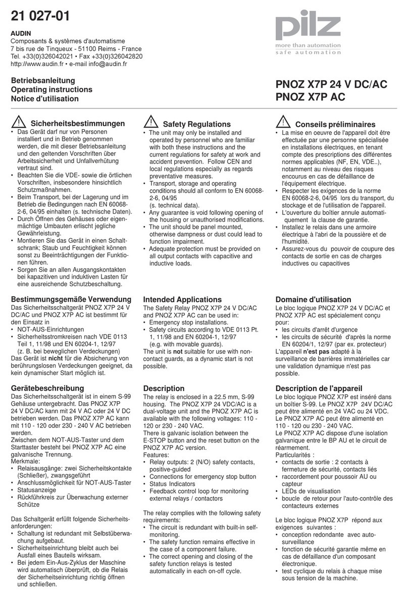
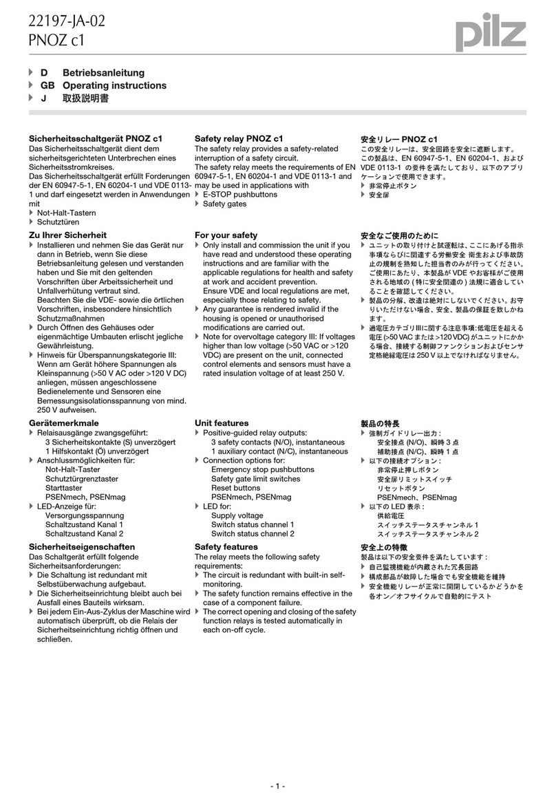
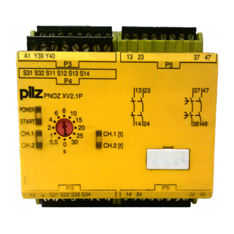
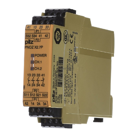
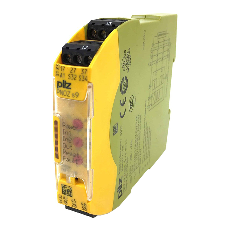
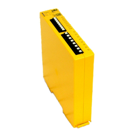
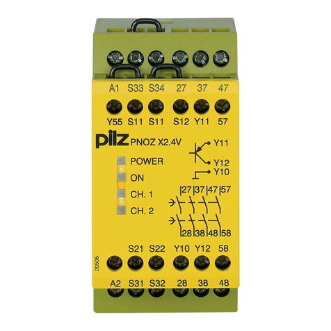
Pilz P1HZ 2 User manual

- 1 -
Sicherheitsbestimmungen
• Das Gerät darf nur von Personen installiert
und in Betrieb genommen werden, die mit
dieser Betriebsanleitung und den gelten-
den Vorschriften über Arbeitssicherheit
und Unfallverhütung vertraut sind.
Beachten Sie die VDE- sowie die örtlichen
Vorschriften, insbesondere hinsichtlich der
Schutzmaßnahmen.
• Beim Transport, bei der Lagerung und im
Betrieb die Bedingungen nach EN 60068-
2-6, 01/00 einhalten (s. techn. Daten).
• Durch Öffnen des Gehäuses oder eigen-
mächtige Umbauten erlischt die Gewähr-
leistung.
• Montieren Sie das Gerät in einen Schalt-
schrank; Staub und Feuchtigkeit können
sonst zu Beeinträchtigungen der Funktio-
nen führen.
• Sorgen Sie an allen Ausgangskontakten
bei kapazitiven und induktiven Lasten für
eine ausreichende Schutzbeschaltung.
• Das Gerät darf nur wie in den Anschluß-
beispielen im Kapitel "Anwendung"
angeschlossen werden.
Be
stimmungsgemäße Verwendung
Das Gerät erfüllt die Anforderung Typ III A
nach EN 574.
ACHTUNG!
Das P1HZ 2 darf nicht in Pressensteuerun-
gen eingesetzt werden. Hierfür empfehlen
wir die Zweihandbedienungsrelais P2HZ 5
und P2HZ 6. Es ist nur für den Einsatz bei
einer durch die Risikoanalyse ermittelten
geringen Gefährdung geeignet
(z. B. DIN EN 954-1 Kat. B oder 1, 03/97).
Das Zweihandbedienungsrelais P1HZ 2
dient als Handschutzeinrichtung Typ IIIA
nach EN 574 an Maschinen bzw. Anlagen.
Das Gerät zwingt den Bediener die Hände
während gefahrbringender Bewegungen
außerhalb des Gefahrenbereichs zu halten.
Das P1HZ 2 ist bestimmt für den Einsatz in
Zweihandschaltungen. Beachten Sie dabei
die Typenangabe der Zweihandschaltung
aus der entsprechenden C-Norm.
Gerätebeschreibung
Das Zweihandbedienungsrelais ist in einem
P-75-Gehäuse untergebracht. Es stehen ver-
schiedene Varianten für den Betrieb mit
Wechselspannung und eine Variante für den
Betrieb mit 24 V Gleichspannung zur
Verfügung.
Merkmale:
• Relaisausgänge:
2 Sicherheitskontakte (S), zwangsgeführt
• Anschluß für zwei Bedienelemente (Taster)
• redundante Ausgangsschaltung
• Rückführkreis zur Überwachung externer
Schütze
Conseils préliminaires
• La mise en oeuvre de l'appareil doit être
effectuée par une personne spécialisée en
installations électriques, en tenant compte
des prescriptions des différentes normes
applicables (NF, EN, VDE..), notamment
au niveau des risques encourus en cas de
défaillance de l'équipement électrique.
• Respecter les exigences de la norme
EN 60068-2-6, 01/00 lors du transport, du
stockage et de l’utilisation de l’appareil.
• Toutes interventions sur le boîtier
(ouverture du relais, échange ou
modification de composants, soudure etc..)
faites par l'utilisateur annulent la garantie.
• Montez l'appareil dans une armoire
électrique à l'abri de l'humidité et de la
poussière.
• Assurez-vous du pouvoir de coupure des
contacts de sortie en cas de charges
inductives ou capacitives.
• Le relais de commande bimanuelle doit
être câblé que comme indiqué dans le
paragraphe "Utilisation"
Domaines d'utilisation
L'appareil répond aux exigences de la norme
EN 574 pour les relais de type III A.
Attention !
Le relais P1HZ 2 n’est pas adapté pour les
circuits de commande des presses. Nous
vous conseillons, dans ce cas, l’utilisation
des relais P2HZ 5 et P2HZ 6.
Il n'est
adapté
que pour les circuits dont la catégorie
de
risque est faible ( EN 954-1 cat. B ou1, 07/
96).
Le relais de commande à deux mains
P1HZ 2 est un dispositif de sécurité de type
III A d'après EN 574. L'appareil protége
l'opérateur contre les risques de blessure en
l'obligeant à avoir les 2 mains hors de la
zone dangereuse de la machine. Il ne doit
pas être installé sur les presses à métaux.
Le P1HZ 2 peut être utilisé comme relais de
commande bimanuelle. Vérifer le type de la
commande bimanuelle à installer suivant les
différentes normes C.
Description de l'appareil
Inséré dans un boîtier P-75 , le bloc logique
de sécurité est disponible en différentes
versions pour les tensions alternatives et une
version en continue (24 V).
Caractéristiques :
• Contact de sortie :
2 contacts à fermeture de sécurité (F).
• Borne de raccordement pour les 2
poussoirs de commande
• Sorties redondantes.
• Boucle de retour pour l'auto-contrôle de
contacteurs externes.
Safety Regulations
• The unit may only be installed and
operated by personnel who are familiar
with both these instructions and the current
regulations for safety at work and accident
prevention. Follow local regulations
especially as regards preventative
measures.
• Transport,storage and operating conditions
should all conform to EN 60068-2-6, 01/00.
• Any guarantee is void following opening of
the housing or unauthorised modifications.
• The unit should be panel mounted,
otherwise dampness or dust could lead to
functional impairment.
• Adequate protection must be provided on
all output contacts with capacitive and
inductive loads.
• The unit may only be connected as shown
in the examples in the section "Application"
Intended use
The unit fulfils the requirements to EN 574
Type III A.
CAUTION!
The P1HZ 2 is not for use as a safety switch
unit in press controlling. For press control-
ling we recommend the two-hand control
relays P2HZ 5 and P2HZ 6.
It has been
designed for use where the risk of danger is
limited, determined through detailed risk
analysis (e.g. EN 954-1 cat B or 1, 07/96).
The Two-Hand Control Relay P1HZ 2 serves
as a hand protection device Type IIIA in
accordance with EN 574 on machinery and
plants. The unit guides and keeps the hands
of the user away from the danger zone during
hazardous movements.
It may not be used with metal processing
presses. The P1HZ 2 is for the use in 2-hand
relays. Follow type details of the 2-hand-relay
from the corresponding C standard.
Description
The two-hand control relay is enclosed in a P-
75 housing. There are different versions
available for AC operation and 1 unit for
24 VDC operation.
Features:
• Relay outputs:
2 safety contacts (n/o), positive-guided
• Connection for 2 operating elements
(buttons).
• Output circuit is redundant
• Feedback control loop for monitoring
external contactors/relays
17 554-01
P1HZ 2 (Typ III A, EN 574)
4D Betriebsanleitung
4GB Operating instructions
4F Manuel d'utilisation
4E Instrucciones de uso
4I Istruzioni per l`uso
4NL Gebruiksaanwi zing

- 2 -
Das Schaltgerät erfüllt folgende Sicherheits-
anforderungen:
• Das Zweihandbedienungsrelais verhindert
in folgenden Fällen die Freigabe der
Anlage:
- Spannungsausfall
- Ausfall eines Bauteils
- Kurzschluß eines Eingangskreises
- Spulendefekt
- Leiterbruch
- Erdschluß
• Überprüfung bei jedem Ein-Aus-Zyklus, ob
die Ausgangsrelais des Sicherheitsgerätes
richtig öffnen und schließen
Funktionsbeschreibung
Das Zweihandbedienungsrelais P1HZ 2 ist
Teil der gesamten Zweihandschaltung, die
als ein sicheres System der Vermeidung von
Handverletzungen an gefahrbringenden
Maschinen dient. Sie besteht neben dem
Zweihandbedienungsrelais aus zwei
Bedienelementen (z. B. Taster) und einer
sicherheitsgerichteten Maschinensteuerung.
Sobald die Versorgungsspannung UBanliegt
und der Rückführkreis geschlossen wird, ist
das Gerät startbereit.Das Zweihand-
bedienungsrelais wird durch gleichzeitiges
Betätigen (Gleichzeitigkeitsbedingung tg) der
beiden Bedienelemente aktiviert. Es
unterbricht bei Loslassen eines oder beider
Bedienelemente den Steuerbefehl für die
gefährliche Bewegung.
Le relais répond aux exigences suivantes :
• Fonction de sécurité garantie en cas de :
- Défaillance tension
- Défaillance d'un composant
- Court-circuit dans les canaux d'entrée
- Défaillance bobine
- Défaut soudure
- Défaut de masse
• Vérification à chaque cycle marche/arrêt,
du bon fonctionement des relais de sortie
Description du fonctionnement
Le relais P1HZ 2 est une partie du système
de commande bimanuelle qui permet de
protéger les opérateurs contre des blessures
éventuelles aux mains sur des machines
dangereuses. Le système de commande
bimanuelle se compose, en plus du relais à 2
mains, de 2 éléments de commande
(poussoirs) et d'un circuit de commande
conforme aux normes de sécurité.
Dès que la tension d'alimentation UBest
appliquée et que la boucle de retour est
fermée, le relais est prêt à fonctionner. Le
relais P1HZ 2 est activé par l'action
simultanée (désynchronsime tg) sur les 2
poussoirs de commande. Le relâchement
d'un des 2 poussoirs entraîne la retombée du
contact de sortie et l'arrêt du mouvement
dangereux.
The relay complies with the following safety
requirements:
• The two-hand control relay prevents
machine operation in the following cases:
- Power supply failure
- Component failure
- Short circuit in the input circuits
- Coil defect in a relay
- Cable break
- Earth fault
• The correct opening and closing of the
Safety Gate limit switches and the safety
function output relays is tested
automatically in each on-off cycle
Function Description
The two-hand control relay P1HZ 2 forms
part of a 2 hand control system that serves
as a safety system against hand injuries from
dangerous parts of machinery. In addition to
the two-hand control relay, the P1HZ 2
requires two operating elements (i.e. button)
and appropriate safety measues suitable for
machine control.
When the operating voltage UBis supplied
and the feedback control loop is closed, then
the unit is ready for operation. The two-hand
control relay via simultaneous operation
(Simultaneous operation tg ) of the two
operating elements will be operated. It
interrupts the control command and therefore
the dangerous movement, by releasing one
or both of the operating elements.
Funktionsablauf
• Werden die Taster 1 und 2 "gleichzeitig",
d. h. innerhalb von 0,5 s betätigt, gehen
die beiden Ausgangsrelais K1 und K2 in
Arbeitsstellung und die Sicherheits-
kontakte 13-14 und 23-24 schließen.
• Die Ausgangsrelais ziehen nicht an, wenn
- nur ein Bedienelement betätigt wird
- die Gleichzeitigkeit überschritten wird
- der Rückführkreis noch offen ist
• Wird nach gleichzeitigem Betätigen ein
Bedienelement losgelassen, fallen die
Ausgangsrelais wieder ab. Die zwangs-
geführten Sicherheitskontakte 13-14 und
23-24 öffnen. Die Ausgangsrelais spre-
chen erst dann wieder an, wenn beide
Bedienelemente losgelassen und erneut
gleichzeitig betätigt werden.
Modes of Operation
• Should the buttons 1 and 2 be
"simultaneously" pressed (i.e. within 0.5 s)
both output relays K1 and K2 energise
and the safety contacts 13-14 and 23-24
close.
• The output relays do not energise if:
- only one operating element is activated
- the simultaneity period tgis exceeded
- the feedback control loop is open
• Should an operating element be released
after being simultaneously operated, the
output relays de-energise. The positive
guided safety contacts 13-14 and 23-24
open. The output relays energise again
only after both operating elements have
been released and then once again
simultaneously operated.
Fonctionnement
• Si les poussoirs 1 et 2 sont actionnés
"simultanément" ou dans un intervalle
inférieur à 0,5 sec, les relais de sortie K1
et K2 passent en position travail. Les
contacts de sécurité 13-14 et 23-24 se
ferment.
• Les relais de sortie ne passent pas en
position travail si :
- un seul poussoir est actionné ou
- le temps de désynchronisme est
dépassé.
- la boucle de retour est ouverte.
• Le relâchement d'un des poussoirs fait
retomber les relais de sortie. Les contacts
13-14 et 23-24 s'ouvrent. Une nouvelle
fonction ne peut être obtenue qu'en
relâchant les 2 poussoirs et en les
actionnant à nouveau simultanément.
+
P1HZ 2
T14 T24T13 T23
X2X1
T1
G1
A2
(L-)
U
B
~
=K2K1
A1
(L+)
Rückführkreis
Feedback Control Loop
Boucle de retour
13 23
14 24
K1
K2
1
3
(S2)(S1)
Eingangskreis 1
Input circuit 1
Canal d'entrée 1
Eingangskreis
Input circuit
Canal d'entrée
Fig. 1: Schematisches Schaltbild/Wiring diagram/Schéma interne
Einschaltlogik/zyklischer Test
Start-up logic/cycle test
Logique de commande/Test cyclique
Kanal 1
Channel 1
Canal 1
Kanal 2
Channel 2
Canal 2
1
2
3

- 3 -
Sicherheitsfunktionen
Die Steuerlogik prüft vor jedem Wiederein-
schalten, ob die Ausgangsrelais zuvor
vollständig abgefallen sind bzw. wieder
anziehen. Im Fall einer Kontaktverschweis-
sung oder eines Drahtbruches ist ein
Wiedereinschalten nicht möglich.
Wird nach EN 60204 T 9.4.3.1 die Phase
Li(-) der Versorgungsspannung auf
Erdpotential gelegt, werden Erdschlüsse
erkannt. Bei Erdschlüssen im Eingangs- oder
Rückführkreis bricht die interne Versorgungs-
spannung zusammen und die Ausgangs-
relais fallen ab oder die Ausgangsrelais
ziehen beim nachfolgenden Start nicht mehr
an.
Betriebsart
Das P1HZ 2 arbeitet im zweikanaligen
Betrieb:
•
zwei redundante (d. h. identische) Ein-
gangskreise wirken auf Kanal 1 und Kanal 2
• Überwachung der Kontakte im Eingangs-
kreis (Ausfallsicherheit gegen Kurzschluß)
Safety Functions
Each time the unit is switched on, the start-
up logic first checks if the output relays are
fully de-energised. In the case of a welding
of contacts or cable break, the unit cannot be
activated.
Should the phase L(-) of the operating
voltage, to EN 60204 T9.4.3.1. be conected
to the earth point, accidental earth fault will
be detected. With accidental earths in the
input circuit or feedback control loop, the
internal operating voltage will fail and the
output relays will de-energise or the output
relays, following a reset will not energise.
Operating modes
The P1HZ 2 is for two-channel operation:
• Two redundant (i.e. identical) input circuits
operate channel 1 and channel 2.
• Monitoring of contacts in the input circuit
(fail to safe in the event of short circuit)
Fonctions de sécurité
Le bloc logique teste avant chaque remise
sous tension si les relais de sortie sont bien
retombés. En cas de soudage d'un contact
ou d'une coupure de fil, une remontée du
relais n'est plus possible.
Si la phase L(-) de la tension d'alimentation
du relais est reliée à la terre selon la norme
EN 60204 T 9.4.3.1, les mises à la terre sont
détectées. En cas de mise à la terre dans un
des circuit d'entrée ou dans la boucle de
retour, la tension interne s'écroule et les
relais de sortie retombent ou ne remontent
pas à la prochaine impulsion de commande.
Mode de fonctionnement
Le relais P1HZ 2 travaille avec 2 canaux
d'entrée :
• 2 circuits d'entrée redondants (c.à.d
identiques) sont connectés aux canaux 1
et 2.
• Surveillance des contacts dans les canaux
d'entrée (détection de courts-circuits).
Fig. 2: Funktionsdiagramm/Pulse diagram/Diagramme fonctionnel
0
1
0
1
0
1
0
1
0
1
1
0
B
U
g
t
(1) (2) (3) (4)
(6)
(5)
g
t
Rückführkreis
Feedback Control Loop
Boucle de retour
Betriebsspannung
Operating Voltage
Tension d'alimentation
Eingangskreis 1
Input circuit 1
Canal d'entrée 1
Eingangskreis
Input circuit
Canal d'entrée
Ausgang
Output
Sortie
Gleichzeitigkeit
Simultaneity
Désynchronisme g
tg
tg
t
(1) = Normaler Arbeitszyklus (1) = Normal work cycle (1) = Functionnement normal
(2) = Fehlbedienung: Rückführkreis (2) = Fault condition: Close feedback control (2) = Défaut : la boucle de retour doit être
min. 0,5 s vor S1, S2 schließen loop min. 0.5 s before S1, S2 fermée min. 0,5 s. avant
(3) = Fehlbedienung: Differenz S1, S2 > tig(3) = Fault condition: Delay S1, S2 > tig(3) = Défaut : synchronisation S1, S2 > tig
(4) = Fehlbedienung: S1 und S2 vor UiB(4) = Fault condition: S1 and S2 before UiB(4) = Défaut : S1 et S2 actionné avant UiB
(5) = Fehlbedienung: Rückführkreis (5) = Fault condition: Keep feedback control (5) = Défaut : boucle de retour ouverte
nicht vor Ablauf tgöffnen closed until tg is activated avant fin du désynchronisme tg
(6) = Zeitdifferenz beliebig (6) = Time delay adjustable (6) = Désynchronisme quelconque

- 4 -
Montage
Das Gerät muß in einen Schaltschrank mit
einer Schutzart von mind. IP 54 eingebaut
werden. Zur Befestigung auf einer Norm-
schiene hat das Gerät ein Rastelement auf
der Rückseite.
ACHTUNG!
Der Abstand der Bedienelemente des
Zweihandbedienungsrelais von der
nächst gelegenen Gefahrenstelle muß so
groß sein, daß beim Loslassen auch nur
eines Bedienelementes die gefährliche
Bewegung unterbrochen wird, bevor der
Bediener die Gefahrenstelle erreicht bzw.
bevor der Bediener in die Gefahrenstelle
hineingreifen kann (siehe prEN 999
"Hand-Arm-Geschwindigkeit").
Inbetriebnahme
Beachten Sie bei der Inbetriebnahme:
•Vor die Ausgangskontakte eine
Sicherung (6 A flink oder 4 A träge)
schalten, um das Verschweißen der
Kontakte zu verhindern.
• Keine kleinen Ströme (z. B. 30 mA) mit
Kontakten schalten, über die zuvor große
Ströme geführt wurden.
• Bei der Auswahl und der Montage der
beiden Bedienelemente die Anforderungen
nach EN 574 in Bezug auf Betätigung und
Umgehung einhalten.
• Leitungsmaterial aus Kupferdraht mit einer
Temperaturbeständigkeit von 60/75 °C
verwenden.
• Das Anzugsdrehmoment der Schrauben
auf den Anschlußklemmen darf max.
1,2 Nm betragen.
• Angaben im Kapitel "Technische Daten"
unbedingt einhalten.
Anschluß
• Betriebserde an Klemme T24 anschließen
(nur bei AC-Geräten)
.
• Versorgungsspannung an Klemmen A1
(L+) und A2 (L-) anschließen.
• Die Versorgungsspannung muß mit der
Antriebsenergie (Hauptschalter, NOT-
AUS) der Anlage abgeschaltet werden.
• Bei Geräten für 24 V DC können Quer-
schlüsse zwischen Eingangskreis 1 bzw.
Rückführkreis und dem Eingangskreis 2
das Gerät beschädigen. Die Verwendung
einer kurzschlußfesten Spannungs-
versorgung mit Strombegrenzung wird
empfohlen.
• Eingangskreis
- Jeweils nur ein Bedienelement an T13,
T14 und an T23, T24 anschließen.
-Bitte beachten: nur Schließerkontakte
anschließen.
• Rückführkreis
Öffnerkontakte der zu überwachenden
Schütze am Rückführkreis X1-X2
anschließen oder - wenn nicht benötigt -
Brücke X1-X2 einlegen.
Montage
Le relais doit être installé dans une armoire
équipée d'une protection IP 54. Sa face
arrière permet un montage sur rail DIN.
ATTENTION !
L'implantation des organes de commande
doit être telle qu'un opérateur lâchant un
organe de service ne puissa atteindre la
zone dangereuse avant l'arrêt des
éléments mobiles dangereux (voir norme
prEN 999).
Mise en oeuvre
Remarques préliminaires :
• Protection des contacts de sortie par
des fusibles 6A rapides ou 4A normaux
pour éviter leur soudage.
• Ne pas commuter de petites intensités (par
ex. 30 mA) avec des contacts qui ont
précédemment coupé de fortes intensités.
• Tenir compte des exigences de la norme
EN 574 lors du choix et de l'installation des
éléments de commande.
• Utiliser uniquement des fils de cablâge en
cuivre 60/75 °C.
• Le couple de serrage sur les bornes de
racordement ne doît pas dépasser
1,2 Nm.
• Respecter les données indiquées dans le
chapitre "Caractéristiques techniques".
Branchement
• Relier la borne T24 à la terre (uniquement
appareils en AC).
• Ramener la tension d'alimentation entre
les bornes A1 (L+) et A2 (L-)
• La tension d'alimentation du P1HZ 2 doit
être coupée avec la tension de puissance
(sectionneur, AU) de la machine.
• Utiliser une alimentation régulée et
protégée contre les courts-circuits pour les
appareils alimentés en 24 VCC car un
court-circuit entre le canal 1 ou la boucle
de retour et la canal 2 risque d'endom-
mager le relais.
• Organes de commande :
- ne câbler qu'un seul poussoir par canal
d'entrée T13-14 et T23-T24
- Remarque : n'utiliser que des contacts
à fermeture
• Boucle de retour :
Câbler les contacts à ouverture des
contacteurs à surveiller dans la boucle de
retour X1-X2 ou - quand ce n'est pas
nécessaire - relier les bornes X1-X2.
Installation
The unit must be panel mounted (min.
IP 54). There is a moulding on the rear of
the unit for DIN-Rail attachment.
CAUTION!
The location of the operating elements of
the two-hand control relay must be far
enough away from the hazardous area of
the machine such that releasing any one
of the operating elements will stop any
machinery operation before the user can
reach into the hazardous area. (see
prEN 999 "Hand/Arm Speed"
Operation
Please note for operation:
• To prevent contact welding, a fuse (6 A
quick or 4 A slow acting) must be
connected before the output contacts.
• Low currents (e.g. 30 mA) should not be
switched across contacts through which
high currents have previously been
switched.
• When choosing and installing 2-hand
controls, it is important to comply with the
requirements of EN 574.
• Use copper wiring that will withstand
60/75 °C
• Tighten terminals to 1.2 Nm.
• Important details in the section "Technical
Data" should be noted and adhered to.
Connection
• Connect the operating earth (AC units
only).
• Connect the operating voltage between
A1i(+) and A2 (-).
• If the main power (main switch or
Emergency Stop) of the equipment must
be switched off then so too must the
operating voltage of the unit.
• With 24 VDC, shorts across the key
contacts between input circuit 1 or the
feedback control loop and the input circuit
2 can cause damage to the unit.
• It is recommended to use a short circuit
proof voltage supply with current
limitations.
• Input Circuit
- At any one time connect only one
operating element to T13, T14 and one
to T23 and T24.
- Please note: Only connect N/O contacts
• Feedback control loop
Connect the N/C contact of the relay to be
monitored to the feedback control loop
X1-X2 or - if not needed - bridge X1-X2.

- 5 -
Ablauf
Das Gerät ist eingeschaltet, wenn
• die Versorgungsspannung anliegt
• der Rückführkreis geschlossen ist
• die Bedienelemente (Eingangskreise)
gleichzeitig betätigt werden
Die Sicherheitskontakte 13-14 und 23-24
sind geschlossen. Werden ein oder beide
Bedienelemente losgelassen, öffnen die
Sicherheitskontakte 13-14 und 23-24.
Wieder aktivieren
• Beide Bedienelemente loslassen und
wieder gleichzeitig betätigen.
• Ggf. die Versorgungsspannung wieder
einschalten (z. B. NOT-AUS betätigt).
Anwendung
In dem Beispiel nach Fig. 3 wird der
Rückführkreis nicht verwendet. Für Anwen-
dungen mit externen Schützen muß Fig. 3
gemäß dem Beispiel in Fig. 4 erweitert
werden.
Der Rückführkreis dient zur Überwachung
externer Schütze, die zur Kontaktverstärkung
oder Vervielfältigung verwendet werden
(Fig. 4).
Mise en oeuvre
L'appareil est activé lorsque :
• la tension d'alimentation est appliquée.
• la boucle de retour est fermée.
• les 2 poussoirs de commande sont
actionnés en même temps.
Les contacts de sécurité 13-14 et 23-24 sont
fermés. Le relâchement d'un ou des 2
poussoirs fait retomber les relais de sortie.
Les contacts 13-14 et 23-24 s'ouvrent.
Réarmement
• Relâchement des 2 poussoirs puis
nouvelle action simultanée sur les BP
• Eventuellement remettre sous tension
l'installation (AU actionné)
Utilisation
Dans le schéma de branchement de la fig. 3,
la boucle de retour n'est pas utilisée. En cas
d'utilisation de relais externes, le câblage de
la fig. 3 doit être complété selon l'exemple de
branchement 4.
La boucle de retour sert au contrôle de
contacteurs externes, qui sont utilisés pour
augmenter le pouvoir de coupure ou le
nombre de contacts (fig. 4).
To operate
The unit is activated when:
• The operating voltage is supplied
• The feedback control loop is closed
• The operating elements (input circuits) are
simultaneously operated
The safety contacts 13-14 and 23-24 are
closed. Should one or both of the operating
elements be released, the safety contacts
13-14 and 23-24 will open.
Reactivation
• Release both operating elements and then
simultaneously operate them again.
• Should the need arise, switch the
operating voltage on (e.g. operate
Emergency stop).
Application
In the example in Fig. 3 the feedback control
is not used. For application with external
relays, Fig. 3 must be expanded to comply
with the example in Fig. 4.
The Feedback control loop is for the
monitoring of external relays to increase the
number of available contacts (Fig. 4).
Das Gerät nur wie in den folgenden Only connect the unit as shown in the Câbler l'appareil uniquement comme
Abbildungen anschließen! following examples! l'indiquent les schémas suivants!
14
K3 K4
13
P1HZ 2
X1 X2
K3 K4
1L1
(1L+)
1L2
(1L-)
F2
T14
T13
A1
(+)
T24
T23
S2
S1
A2
(-)
X2
13
14
P1HZ 2
23
24
X1
1L1
(1L+)
1L2
(1L-)
F1
Fig. 3: Anschlußbild
(F1, F2 s. "Technische Daten")
Connection diagram
(F1, F2 see "Technical Data")
Commande par deux canaux
(F1, F2 voir "Caractéristiques tecniques")
Fig. 4: Anschlußbeispiel für externe
Schütze, einkanalig/Connection
example for external contactors/
relays, single-channel/Branchement
contacteurs externes, commande
par 1 canal

- 6 -
Abmessungen in mm ('')/Dimensions in mm ('')/Dimensions en mm ('')
116 (4.57")
110 (4.33")
75 (2.95") 45 (1.77")
Überprüfung - Fehlerursachen
Durch Schließen bzw. Unterbrechen der
Eingangskreise kann überprüft werden, ob
das Gerät ordnungsgemäß ein- bzw.
ausschaltet.
Das Gerät kann aus Sicherheitsgründen bei
folgenden Fehlern nicht gestartet werden:
• Fehlfunktion der Kontakte:
Bei verschweißten Kontakten ist nach
Öffnen der Eingangskreise keine neue
Aktivierung möglich.
• Leitungsunterbrechung, Kurz- oder
Erdschluß (z. B. im Eingangskreis)
Testing - Fault causes
By interrupting the input circuit, the correct
de-energisation of the unit can be tested.
For safety reasons, the unit cannot be
activated if the following faults are present:
• Faulty contact functions:
In the case of welded contacts, no further
activation is possible following an opening
of the input circuit.
• Cable break, short-circuit or earth fault
(e.g. in the input circuit).
Vérification - Sources d'erreur
On vérifie par l'ouverture des canaux
d'entrée la bonne retombée du relais de
sortie.
Pour garantir la fonction de sécurité, le relais
n'est pas réarmé en cas des défauts
suivants :
• Défaut des contacts de sortie : en cas de
soudage d'un contact lors de l'ouver- ture
du circuit d'entrée, un nouveau
réarmement est impossible.
• Coupure d'un canal d'entrée, court-circuit
ou défaut de masse dans les canaux
d'entrée sont détectés.

- 7 -
Technische Daten/Technical Data/Caractéristiques techniques
Elektrische Anforderungen/Electrical Data/Caractéristiques électriques
Versorgungsspannung UB /Operating Voltage UB /Tension d'alimentation UBAC:24/42/110/115/120/230/240 V
DC: 24 V
Spannungstoleranz UB /Voltage Tolerance UB /Plage de la tension d'alimentation UB85-110 %
Restwelligkeit UB /Residual Ripple UB /Ondulation résiduelle UBmax. 20 %
Leistungsaufnahme bei UB /Power Consumption at UB /Consommation UBca./appx./env. AC: 4 VA; DC: 2 W
Kontakte/Contacts/Contacts
Ausgangskontakte 2 Sicherheitskontakte (S)
Output Contacts 2 Safety Contacts (N/O)
Contacts de sortie 2 contacts de sécurité (F)
Kontaktwerkstoff/Contact Material/Matériau des contacts AgSnO2
Schaltvermögen nach/Switching Capability to/Caractéristiques de commutation d'après
EN 60947-4-1, 02/01 AC1: 240 V/0,01 ... 6 A/1500 VA
DC1: 24 V/0,01 ... 1,5 A/40 W
EN 60947-5-1, 11/97 (DC13: 6 Schaltspiele/Min, 6 cycles/min, 6 manoeuvres/min) AC15: 230 V/2,5 A; DC13: 24 V/1,5 A
Mechanische Lebensdauer/Mechanical Life/Durée de vie mécanique 1 x 10⁷ Schaltspiele/cycles/manoeuvres
Elektrische Lebensdauer/Electrical Life/Durée de vie électrique (1A/230V AC, cos.ϕ.=.1) 1 x 10⁵Schaltspiele/cycles/manoeuvres
Eigenschaften/Features/Particularités
Rückfallverzögerung/Delay-on De-Energisation/Temps de retombée ca./appx./env. 30 ms
(Ansprechverzögerung nach/Delay-on Energisation to/Temps de montée d'après EN 574)
Gleichzeitigkeitsbedingung (max. Zeitdifferenz tgzwischen Eingangskreis 1 und 2) max. 500 ms
Simultaneity Requirements (max. Time delay tgbetween input circuit 1 and 2)
Synchronisation temporelle (différence de temps tgentre les canaux d'entrée 1 et 2)
Spannung und Strom an den Eingängen T13-T14 und T23-T24 24 V DC, 40 mA
Voltage and Current at inputs T13-T14 and T23-T24
Tension et courant aux entrées T13-T14 et T23-T24
Grenzbelastbarkeit/Loading capacity limit/Caractéristiques de commutation
Elektromagnetische Verträglichkeit (EMV)/Electromagnetic Compatibility to EN 50081-1, 01/92
Compatibilité électromagnétique (CEM) d'apres EN 61000-6-2, 03/00
Luft- und Kriechstrecken nach/Airgap Creepage/Cheminement et claquage DIN VDE 0110 Teil/Part/Partie 1, 04/97
Kontaktabsicherung F2/Contact Fuse Protection F2/Protection des contacts de sortie F2 max. 6 A flink/quick/rapide oder/or/ou
(EN 60947-5-1, 08/00) max. 4 A träge/slow acting/normal
Geräteabsicherung F1 min./max. 1 A/abhängig vom Leitungsquerschnitt
Unit Fuse Protection F1min./max. 1 A/dependentoncablecross section
Protection du relais F1 min./max. 1 A/dépend du diamêtre du câblage
Umgebungsbedingungen/EnvironmentConditions/Environnement
Umgebungstemperatur/Operating Temperature/Température d'utilisation -10 ... +55 °C
Lagertemperatur/Storage Temperature/Température de stockage -40 ... +85 °C
Klimabeanspruchung/Climate Suitability/Conditions climatiques DIN IEC 60068-2-3, 12/86
Schwingungen nach/Vibration to/Vibrations d'aprés EN 60068-2-6, 01/00 Frequenz/Frequency/Fréquences: 10...55Hz
Amplitude/Amplitude/Amplitude: 0,35 mm
Allgemeine Angaben zum Gerät/General Information - Unit/Caractéristiques du boîtier
Anforderungsklasse nach/Requirement Class to/Catégorie selon EN 574, 1996 Typ/Type/Type III A
Max. Anschlußquerschnitt (Einzelleiter und mehrdrähtiger Leiter mit Aderendhülsen) 2 x 2,5 mm²
Max. cable cross section (single-core or multicore with crimpconnectors)
Max. raccordement (conducteur unique ou multiple avec embout)
Anzugsdrehmoment für Anschlußschrauben (Klemmen)/torque setting for connection terminal
1,2 Nm
screws/
couple de serrage (bornier)
Schutzarten/Protection/Indice de protection:
Einbauraum (z. B. Schaltschrank)/Mounting (e.g. Panel)/Lieu d'implantation (ex. armoire) IP 54
Gehäuse/Housing/Boîtier IP 40
Klemmenbereich/Terminals/Bornes IP 20
Gehäusematerial (Kunststoff)/Housing material (synthetic)/Matériau du boîtier (matiére artificielle) Noryl SE 100
Abmessungen (H x B x T)/Dimensions (H x W x D)/Dimensions (H x L x P) 75 x 45 x 110 mm (2.95" x 1.77" x 4.33")
Gewicht/Weight/Poids AC: 380 g; DC: 280 g

- 8 -
A Pilz Ges.m.b.H., ✆01 7986263-0, Fax: 01 7986264, E-Mail: [email protected] AUS Pilz Australia, ✆03 95446300, Fax: 03 95446311, E-Mail:
[email protected] B L Pilz Belgium, ✆09 3217570, Fax: 09 3217571, E-Mail: [email protected] BR Pilz do Brasil, ✆11 4337-1241, Fax: 11 4337-1242,
E-Mail: pilz@pilzbr.com.br CH Pilz lndustrieelektronik GmbH, ✆062 88979-30, Fax: 062 88979-40, E-Mail: [email protected] DK Pilz Skandinavien K/S,
✆74436332, Fax: 74436342, E-Mail: [email protected] E Pilz lndustrieelektronik S.L., ✆938497433, Fax: 938497544, E-Mail: [email protected] F Pilz France
Electronic, ✆03 88104000, Fax: 03 88108000, E-Mail: [email protected] FIN Pilz Skandinavien K/S, ✆09 27093700, Fax: 09 27093709, E-Mail:
pilz.f[email protected] GB Pilz Automation Technology, ✆01536 460766, Fax: 01536 460866, E-Mail: [email protected] I Pilz ltalia Srl, ✆031 789511,
Fax: 031 789555, E-Mail: [email protected] IRL Pilz Ireland Industrial Automation, ✆021 4346535, Fax: 021 4804994, E-Mail: [email protected] J Pilz Japan Co.,
Ltd., ✆045 471-2281, Fax: 045 471-2283, E-Mail: [email protected].jp MEX Pilz de Mexico, S. de R.L. de C.V., ✆55 5572 1300, Fax: 55 5572 4194, E-Mail:
[email protected] NL Pilz Nederland, ✆0347 320477, Fax: 0347 320485, E-Mail: [email protected] NZ Pilz New Zealand, ✆09- 6345-350, Fax: 09-6345-
352, E-Mail: [email protected] P Pilz Industrieelektronik S.L., ✆229407594, Fax: 229407595, E-Mail: [email protected] PRC Pilz China Representative
Office, ✆021 62494658, Fax: 021 62491300,
ROK Pilz Korea, ✆031 8159541, Fax: 031 8159542, E-Mail: info@pilzkorea.co.kr
SE Pilz Skandinavien K/S, ✆0300 13990, Fax: 0300 30740, E-Mail: [email protected] TR Pilz Elektronik Güvenlik Ürünleri ve Hizmetleri Tic. Ltd. ¸Sti.,
✆0224 2360180, Fax: 0224 2360184, E-Mail: [email protected] USA Pilz Automation Safety L.P., ✆734 354-0272, Fax: 734 354-3355, E-Mail:
www www.pilz.com
D Pilz GmbH & Co. KG, Sichere Automation, Felix-Wankel-Straße 2, 73760 Ostfildern, Deutschland, ✆+49 711 3409-0, Fax: +49 711 3409-133,
E-Mail: [email protected]
17 554-01-2006-05 Printed in Germany

- 9 -
Prescripciones de seguridad
• El dispositivo tiene que ser instalado y
puesto en funcionamiento exclusivamente
por personas que estén familiarizadas
tanto con estas instrucciones de uso
como con las prescripciones vigentes
relativas a la seguridad en el trabajo y a
la prevención de accidentes. Hay que
observar tanto las prescripciones VDE
como las prescripciones locales,
especialmente en lo que se refiere a las
medidas de protección.
• Durante el transporte, el almacenaje y el
funcionamiento hay que atenerse a las
condiciones conforme a EN 60068-2-6,
01/00 (ver datos técnicos). Una vez
finalizado su tiempo de vida útil, hay que
eliminar el dispositivo de forma
apropiada.
• La garantía se pierde en caso de que se
abra la carcasa o se lleven a cabo remo-
delaciones por cuenta propia.
• Montar el dispositivo dentro de un
armario de distribución; en caso contrario
es posible que el polvo y la suciedad
puedan afectar el funcionamiento.
• Hay que cuidar de que haya un
conexionado de seguridad suficiente en
todos los contactos de salida con cargas
capacitivas e inductivas.
• Sólo se permite conectar el dispositivo
exclusivamente como en los ejemplos de
conexión del capítulo “Aplicación”.
Campo de aplicación adecuado
El dispositivo satisface los requerimientos
del tipo III A según EN 574.
¡ATENCION!
El P1HZ 2 no debe ser utilizado en
controles de prensas. Para ello
recomendamos los relés de manejo a dos
manos P2HZ 5 y P2HZ 6. Es adecuado sólo
para su aplicación en una peligrosidad
menor, determinada por un análisis de
riesgos (p.ej. DIN EN 954-1 cat. B o bien
1, 03/97). El relé de manejo a dos manos
P1HZ 2 sirve como dispositivo de protección
manual del tipo IIIA según EN 574 en
máquinas o instalaciones. El dispositivo
obliga al operario a mantener las manos
fuera de la zona de peligro mientras que
tienen lugar los movimientos peligrosos. El
P1HZ 2 está concebido para su utilización
en dispositivos de a dos manos. Hay que
observar la indicación de tipo del dispositivo
de a dos manos de la norma C
correspondiente.
Descripción del dispositivo
El relé de manejo a dos manos se
encuentra dentro de una carcasa P-75.
Existen diversas variantes disponibles para
el funcionamiento con tensión alterna y una
variante para el funcionamiento con tensión
continua de 24 V.
Norme di sicurezza
• Il dispositivo può venire installato e
messo in funzione solo da persone che
conoscono bene le presenti istruzioni per
l’uso e le disposizioni vigenti relative alla
sicurezza di lavoro e all’antinfortunistica.
Osservare le disposizioni della VDE
(Associazione tedesca degli Ingegneri)
nonché le norme locali, soprattutto per
quanto riguarda le misure preventive di
protezione.
• Durante il trasporto, l’immagazzinamento
e il funzionamento attenersi alle
condizioni prescritte dalla norma EN
60068-2-6, 01/00 (v. Dati tecnici). Al
termine della propria durata, smaltire il
dispositivo in conformità alle norme
vigenti.
• Se viene aperto l’alloggiamento oppure
se vengono apportate delle modifiche in
proprio decade qualsiasi diritto di
garanzia.
• Montare il dispositivo in un armadio
elettrico; altrimenti la polvere e l’umidità
possono pregiudicare le funzioni.
• Occorre dotare tutti i contatti di uscita dei
carichi capacitivi e induttivi con un
cablaggio protettivo sufficiente.
• Il dispositivo può essere collegato solo
come indicato negli esempi di
connessione al capitolo “Utilizzo”.
Uso previsto
Il dispositivo risponde al requisito di Tipo III
A della norma EN 574.
ATTENZIONE!
Il P1HZ 2 non è adattato ai circuiti di
comando delle presse. In questo caso si
consiglia l’utilizzo dei relè a comando
bimanuale P2HZ 5 e P2HZ 6. Esso è
progettato solo per l’utilizzo in circuiti la cui
categoria di rischio è limitata
(p. es. EN 954-1 cat. B o 1, 03/97).
Il relè a comando bimanuale P1HZ 2 è un
dispositivo di protezione per le mani di tipo
IIIA secondo la norma EN 574 su macchine
o impianti. Esso costringe l’operatore a
tenere le proprie mani fuori dall’area di
pericolo della macchina durante movimenti
rischiosi.
Il P1HZ 2 è destinato esclusivamente
all’impiego come relè di comando
bimanuale. Verificare il tipo di comando
bimanuale da installare in base alla relativa
norma C.
Descrizione
Il relè di comando bimanuale è inserito in un
alloggiamento P-75. Per il funzionamento a
corrente alternata sono disponibili diverse
varianti ed una variante per il
funzionamento
con corrente continua (24 V).
Veiligheidsvoorschriften
• Het apparaat mag uitsluitend worden
geïnstalleerd en in bedrijf genomen door
personen die vertrouwd zijn met deze
gebruiksaanwijzing en met de geldende
voorschriften op het gebied van
arbeidsveiligheid en ongevallenpreventie.
Neem de VDE-voorschriften alsmede de
plaatselijke voorschriften in acht, in het
bijzonder m.b.t. de veiligheidsregels.
• Neem bij transport, opslag en in bedrijf de
richtlijnen volgens EN 60068-2-6, 01/00 in
acht (zie technische gegevens). Het
apparaat na afloop van zijn levensduur op
de juiste wijze verwijderen en opslaan.
• Het openen van de behuizing of het
eigenmachtig aanpassen heeft verlies van
de garantie tot gevolg.
• Monteer het apparaat in een schakelkast.
Stof en vocht kunnen anders de werking
nadelig beïnvloeden.
• Zorg bij alle uitgangscontacten bij
capacitieve en inductieve belastingen
voor voldoende beschermbedrading.
• Het apparaat mag alleen worden
aangesloten zoals in de aansluitvoor-
beelden in het hoofdstuk “Toepassing” is
beschreven.
Gebruik volgens de
voorschriften
Het apparaat vervult de bijzondere eis
type III A volgens EN 574.
ATTENTIE!
Het P1HZ 2 mag niet bij persbesturingen
worden ingezet. Hiervoor adviseren wij de
tweehandenbedieningsrelais P2HZ 5 en
P2HZ 6. Het is alleen geschikt voor het
gebruik bij een gevaarlijke situatie die door
de risicoanalyse is bepaald (bijv. DIN
EN 954-1 cat. B of 1, 03/97).
Het tweehandenbedieningsrelais P1HZ 2
wordt gebruikt als handbescherming type
IIIA volgens EN 574 bij machines resp.
installaties. Het apparaat dwingt de
gebruiker om zijn handen tijdens gevaarlijke
bewegingen buiten de gevarenzone te
houden.
Het P1HZ 2 is bedoeld voor het gebruik in
tweehandenschakelingen. Neem daarbij de
typeaanduiding van de tweehanden-
schakeling uit de desbetreffende C-norm in
acht.
Apparaatbeschrijving
Het tweehandenbedieningsrelais is
ondergebracht in een P-75-behuizing.
Verschillende varianten voor de werking met
wisselspanning en een variant voor de
werking met 24 V gelijkspanning zijn
beschikbaar.
17 554-01
P1HZ 2 (Tipo / Type III A, EN 574)
4E Instrucciones de uso
4I Istruzioni per l`uso
4NL Gebruiksaanwi zing
- 10 -
Características:
• Salidas de relé: 2 contactos de seguridad
(N.A.), con de guía forzosa
• Conexión para dos elementos de manejo
(pulsador)
• Conexión redundante de salida
• Circuito de realimentación para la super-
visión de contactores externos
El dispositivo cumple los requerimientos de
seguridad siguientes:
• El relé de manejo a dos manos impide la
liberación de la instalación en casos de:
- corte de la tensión
- fallo de un elemento constructivo
- cortocircuito de un circuito de entrada
- defecto de bobina
- rotura de línea
- contacto a tierra
• Comprobación con cada ciclo de
conexión/desconexión si los relés de
salida del disp. de seguridad abren y
cierran correctamente
Caratteristiche:
• Uscite relè: 2 contatti di sicurezza (NA), a
guida forzata
• Collegamento per due elementi di
comando (tasti)
• circuito d’uscita ridondante
• Circuito di retroazione per il controllo di
relè esterni
Il modulo risponde ai seguenti requisiti di
sicurezza:
• Il relè a comando bimanuale impedisce il
funzionamento dell’impianto nei casi
seguenti:
- caduta di tensione
- guasto di un componente
- cortocircuito nel circuito d’ingresso
- difetto della bobina
- rottura di cavi
- dispersione a terra
• Per ciascun ciclo di accensione/
spegnimento viene eseguita la verifica
della corretta apertura dei relè di uscita
del disp. di sicurezza
Kenmerken:
• Relaisuitgangen: 2 veiligheidscontacten
(M), mechanisch gedwongen
• Aansluiting voor twee
bedieningselementen (knoppen)
• Redundante uitgangschakeling
• Terugkoppelcircuit ter bewaking ext. relais
Het relais voldoet aan de volgende
veiligheidseisen:
• Het tweehandenbedieningsrelais verhin-
dert in de volgende gevallen het vrijgeven
van de installatie:
- spanningsuitval
- uitval van een component
- kortsluiting van een ingangscircuit
- spoeldefect
- geleiderbreuk
- aardcontact
• Bij elke aan-uit-cyclus wordt
gecontroleerd, of de uitgangrelais van het
veiligheidstoestel op de juiste wijze
openen en sluiten
Descripción del funcionamiento
El relé de manejo a dos manos P1HZ 2 es
parte del dispositivo a dos manos completo
que sirve, en cuanto sistema seguro, para la
evitación de lesiones en las manos en
máquinas peligrosas. Aparte del relé de
manejo a dos manos, se compone de dos
elemento de manejo (p.ej. pulsadores) y un
control de máquina orientado a la seguridad.
El dispositivo se encuentra listo para el
servicio en cuanto que se aplica la tensión
de alimentación UBy se cierra el circuito de
realimentación. El relé de manejo a dos
manos se activa accionando simul-
táneamente (operación simultánea tg)
ambos elemento de manejo. Si se suelta
uno o ambos elementos de manejo, el relé
interrumpe el comando de control del
movimiento peligroso.
Secuencia del funcionamiento
• Si se accionan los pulsadores 1 y 2
“simultáneamente”, es decir, dentro de
0,5 s, entonces los dos relés de salida K1
y K2 se ponen en posición de trabajo y
los contactos de seguridad 13-14 y 23-24
cierran.
• Los relés de salida no se excitan si
- sólo se acciona un elemento de manejo
- no se alcanza la simultaneidad
- el circuito de realimentación está aún
abierto
Descrizione del funzionamento
Il relè a comando bimanuale P1HZ 2 fa
parte del sistema che consente di
proteggere gli operatori da incidenti alle
mani eventualmente provocati da parti
pericolose del macchinario. Oltre al relè a
comando bimanuale esso consiste di due
elementi di comando (p. es. tasti) e di un
circuito di comando conforme alle norme di
sicurezza. Subito dopo l’attivazione della
tensione alimentazione UBe la chiusura del
circuito di retroazione l’unità è pronta per
essere azionata. Il relè a comando
bimanuale sarà attivato tramite il contempo-
raneo azionamento di entrambi gli elementi
di comando (condizione di simultaneità tg).
Con il rilascio di uno o di entrambi gli
elementi di comando viene interrotto
l’impulso di comando per il movimento
pericoloso.
Modalità di funzionamento
• Se i pulsanti 1 e 2 vengono azionati
“contemporaneamente”, cioè entro 0,5 s,
entrambi i relè di uscita K1 e K2 passano
in posizione di lavoro e i contatti di
sicurezza 13-14 e 23-24 si chiudono.
• I relè di uscita non passano in
posizione di lavoro se:
- viene premuto un solo elemento di
comando
- il periodo di simultaneità è stato
superato
- il circuito di retroazione è ancora
aperto
Functiebeschrijving
Het tweehandenbedieningsrelais P1HZ 2 is
een onderdeel van de gehele tweehanden-
schakeling die gebruikt wordt als een veilig
systeem ter voorkoming van verwondingen
aan de handen bij gevaarlijke machines. Zij
bestaat behalve het tweehandenbedienings-
relais uit twee bedieningselementen (bijv.
knoppen) en een veiligheidstechnische
machinebesturing. Zodra er voedingsspan-
ning UBis en het terugkoppelcircuit wordt
gesloten, is het apparaat startklaar. Het
tweehandenbedieningsrelais wordt
geactiveerd door het gelijktijdig indrukken
(gelijktijdigheidsvoorwaarde tg) van de beide
bedieningselementen. Bij het loslaten van
een of van beide bedieningselementen
wordt het startcommando voor de
gevaarlijke beweging onderbroken.
Functieverloop
• Wanneer de knoppen 1 en 2
“tegelijkertijd”, d.w.z. binnen een 0,5 s
worden ingedrukt, gaan de beide
uitgangsrelais K1 en K2 naar de
werkpositie en de veiligheidscontacten
13-14 en 23-24 sluiten.
• De uitgangsrelais zetten niet aan,
wanneer
- slechts één bedieningselement wordt
ingedrukt
- de gelijktijdigheid wordt overschreden
- het terugkoppelcircuit nog open is
+
P1HZ 2
T14 T24T13 T23
X2X1
T1
G1
A2
(L-)
U
B
~
=K2K1
A1
(L+)
Circuito de realimentación /
Circuito di retroazione /
Terugvoercircuit
13 23
14 24
K1
K2
1
3
(S2)(S1)
Circuito de entrada 1 /
Circuito di entrata 1 /
Ingangscircuit 1
Circuito de entrada /
Circuito di entrata /
Ingangscircuit
Fig. 1: Plano de conexiones esquemático / Schema elettrico / Schematisch schakelschema
Lógica de conexión/test cíclico
Logica di controllo/Test ciclico
Inschakellogica/cyclische test
1
2
3
Canal 1
Canale 1
Kanaal 1
Canal 2
Canale 2
Kanaal 2

- 11 -
• Si se suelta un elemento de manejo
después de haber accionado ambos
simultáneamente, entonces los relés se
relajan de nuevo. Los contactos de
seguridad de guía forzosa 13-14 y 23-24
se abren. Los relés de salida se excitan
de nuevo sólo después de que hayan
sido soltados ambos elementos de
manejo y de que hayan sido accionados
simultáneamente una vez más.
Funciones de seguridad
La lógica de control comprueba antes de
cada reconexión si los relés de salida se
han relajado completamente o si se excitan
de nuevo. En caso de una fusión de
contactos o de una rotura de hilo es
imposible la reconexión.
Si, en conformidad con EN 60204 T 9.4.3.1
se pone a potencial de tierra la fase Li(-) de
la tensión de alimentación, entonces se
detectan contactos a tierra. En caso de
contactos a tierra en el circuito de entrada o
de salida, la tensión de alimentación interna
se interrumpe y los relés de salida se
relajan o los relés de salida ya no se excitan
con la siguiente puesta en marcha.
Tipo de funcionamiento
El P1HZ 2 funciona en modo bicanal:
• Dos circuitos de entrada redundantes (es
decir idénticos) actúan sobre canal 1 y
canal 2
• Supervisión de los contactos en el circuito
de entrada (seguridad contra interrupción
por cortocircuito)
• Se dopo l’azionamento simultaneo uno
dei pulsanti viene rilasciato, i relè di
uscita si disattivano nuovamente. I
contatti di sicurezza a guida forzata 13-14
e 23-24 si aprono. I relè di uscita scattano
nuovamente quando entrambi i pulsanti
vengono rilasciati e nuovamente azionati
contemporaneamente.
Funzioni di sicurezza
Ad ogni attivazione dell’unità, la logica di
controllo verifica se i relè di uscita sono
completamente diseccitati. In caso di
saldatura di un contatto o di rottura di un
cavo, non è possibile riattivare l’unità.
Se, secondo la norma EN 60204 T 9.4.3.1,
la fase L i(-) della tensione di alimentazione
è collegata a un potenziale verso terra, le
messe a terra verranno rilevate. In caso di
messa a terra in uno dei circuiti di entrata o
nel circuito di retroazione, la tensione inter-
na crollerà e i relè di uscita si diseccite-
ranno, oppure all’avvio successivo non si
ecciteranno.
Modo operativi:
Il P1HZ 2 opera con 2 canali di entrata:
• Due circuiti di entrata ridondanti (cioè
identici) sono collegati al canale 1 e al
canale 2
• Controllo dei contatti nel circuito di
entrata (fail-safe in caso di cortocircuiti)
• Wanneer na het gelijktijdig indrukken een
bedieningselement wordt losgelaten,
vallen de uitgangsrelais weer af. De me-
chanisch gedwongen veiligheidscontacten
13-14 en 23-24 gaan open. De
uitgangsrelais spreken pas weer aan,
wanneer beide bedieningselementen wor-
den losgelaten en opnieuw tegelijkertijd
ingedrukt.
Veiligheidsfuncties
Elke keer voordat de installatie wordt
ingeschakeld, controleert de besturings-
logica of de uitgangsrelais van tevoren vol-
ledig zijn afgevallen resp. weer aanzetten.
Bij een contactverbinding of een draadbreuk
kan de installatie niet opnieuw worden
ingeschakeld. Wordt volgens EN 60204 T
9.4.3.1 de fase Li(-) van de
voedingsspanning op aardpotentiaal gelegd,
dan worden aardcontacten herkend. Bij
aardcontacten in het ingangs- of
terugkoppelcircuit wordt de interne
voedingsspanning onderbroken en vallen de
uitgangsrelais af, of de uitgangsrelais zetten
bij de volgende start niet meer aan.
Bedrijfsmodus
Het P1HZ 2 werkt in het tweekanalig bedrijf:
• Twee redundante (d.w.z. identieke) in-
gangcircuits werken op kanaal 1 en
kanaal 2
• Bewaking van de contacten in het
ingangscircuit (uitvalbeveiliging tegen
kortsluiting)
Fig. 2: Diagrama funcional / Diagramma funzionale / Functiediagram
0
1
0
1
0
1
0
1
0
1
1
0
B
U
g
t
(1) (2) (3) (4)
(6)
(5)
g
t
Circuito de realimentación /
Circuito di retroazione /
Terugvoercircuit
Tensión de servicio /
Tensione nominale
dimpiego /
Bedrijfsspanning
Circuito de entrada /
Circuito di entrata /
Ingangscircuit
Circuito de entrada /
Circuito di entrata /
Ingangscircuit
Salida /
Uscita /
Uitgang
Simultaneidad /
Simultaneità /
Gelijktijdigheid
g
t
g
t
g
t
(1) = Ciclo normal de trabajo
(2) = Manejo erróneo: circuito de reali-
mentación debe cerrarse como
mín. 0,5 s antes de S1, S2
(3) = Manejo err.: diferencia S1, S2 > tig
(4) = Manejo err.: S1 y S2 antes de UiB
(5) = Manejo erróneo: no abrir circuito de
realimentación antes de transcurrir tg
(6) = Cualquier diferencia temporal
(1) = Ciclo di lavoro normale
(2) = Condizione di errore: il circuito di
retroazione deve essere chiuso
almeno 0,5 s prima di S1, S2
(3) = Cond. di errore: sincronizz. S1, S2 > tig
(4) = Cond. di errore: S1 e S2 prima di UiB
(5) = Condizione di errore: non aprire circ.
retroazione prima dell’attivaz. di tg
(6) = Differenza di tempo regolabile
(1) = normale arbeidscyclus
(2) = bedieningsfout: terugkoppelcircuit
min. 0,5 s voor S1, S2 sluiten
(3) = bedieningsfout: verschil S1, S2 > tig
(4) = bedieningsfout: S1 en S2 voor UiB
(5) = onjuist gebruik: terugkoppelcircuit
niet voor verloop tgopenen
(6) = tijdsverschil naar believen

- 12 -
Montaggio
L’unità deve venire montata in un armadio
elettrico con un grado di protezione di
almeno IP 54. Per il fissaggio su di una
barra DIN l’unità è dotata di un rilievo sul
retro.
ATTENZIONE!
Gli elementi di comando del relè a
comando bimanuale devono essere ad
una sufficiente distanza dalla zona di
pericolo affinché il rilascio anche di uno
solo degli elementi provochi l’interruzione
del movimento pericoloso prima che
l’operatore possa raggiungere la zona in
questione (vedere prEN 999 “Velocità
mano-braccio”).
Messa in funzione
Alla messa in funzione occorre:
•Per evitare la saldatura dei contatti,
collegare un fusibile (6 A rapido o 4 A
lento) prima dei contatti di uscita.
• Non commutare piccole potenze (p. es.
30 mA) con contatti attraverso i quali
sono state commutate in precedenza alte
potenze.
• Per la scelta e il montaggio di entrambi gli
elementi di comando rispettare i requisiti
della norma EN 574.
• Per i cavi usare materiale in filo di rame
con una resistenza termica intorno ai 60/
75 °C.
• La coppia di serraggio massima delle viti
sui morsetti deve essere 1,2 Nm.
• Attenersi assolutamente alle indicazioni
riportate al capitolo “Dati tecnici”.
Collegamento
• Collegare la terra elettrica al morsetto
T24 (solo unità a CA)
.
• Collegare la tensione di alimentazione ai
morsetti A1 (L+) e A2 (L-).
• La tensione di alimentazione deve essere
interrotta assieme all’alimentazione princi-
pale dell’impianto (interruttore principale,
Arresto di emergenza).
• Nel caso di unità alimentate a 24 V CC i
cortocircuiti attraverso il circuito di entrata
1 o il circuito di retroazione e il circuito di
entrata 2 possono danneggiare il relè. Si
consiglia l’utilizzo di un’alimentazione di
tensione a prova di cortocircuito con
limitazione di corrente.
• Circuito di entrata
- Collegare ogni volta solo un elemento
di comando a T13, T14 e a T23, T24.
-Nota: collegare solo i contatti di
chiusura
• Circuito di retroazione
Collegare i contatti chiusi a riposo del relè
da controllare sul circuito di retroazione
X1-X2 oppure, quando non se ne
presenta la necessità, inserire i ponti
X1-X2.
Montaje
El dispositivo tiene que ser montado dentro
de un armario de distribución con un grado
de protección de IP 54 como mínimo. El
dispositivo dispone en su lado trasero de un
elemento de encaje elementos de encaje
para la fijación a una guía normalizada.
¡ATENCION!
La distancia de los elementos de manejo
del relé de manejo a dos manos con
respecto al lugar de peligro más próximo
tiene que ser lo suficientemente grande
como para que, después de soltar sólo
uno de los elementos de manejo, el movi-
miento peligroso se interrumpa antes de
que el operario alcance el lugar de peligro
o antes de que el operario pueda meter la
mano en el lugar de peligro
(ver prEN 999 “Velocidad brazo-mano”).
Puesta en marcha
Al poner en marcha tener en cuenta:
•Conectar un fusible antes de los con-
tactos de salida (6 A de acción rápida
o 4 A de acción lenta) con objeto de
evitar la soldadura de los contactos.
• No conectar corrientes pequeñas (p.ej.
30 mA) con contactos a través de los
cuales se han conducido anteriormente
grandes corrientes.
• Al seleccionar y desmontar ambos
elementos de manejo hay que respetar
los requisitos conforme a EN 574 en
relación al accionamiento y evitación).
• Utilizar para las líneas material de
alambre de cobre con una resistencia a la
temperatura de 60/75 °C.
• El par de apriete de los tornillos en los
bornes de conexión puede ser de 1,2 Nm
como máximo.
• Respetar sin falta las indicaciones del
capítulo “Datos técnicos”.
Conexión
• Conectar tierra de servicio al borde T24
(sólo con dispositivos AC)
.
• Conectar tensión de alimentación en los
bornes A1 (L+) y A2 (L-).
• La tensión de alimentación tiene que ser
desconectada con la tensión de acciona-
miento (interruptor principal, Parada de
emergencia) de la instalación.
• En caso de dispositivos para 24 V DC,
derivaciones entre el circuito de entrada 1
o circuito de realimentación y el circuito
de entrada 2 pueden dañar el aparato. Se
recomienda la utilización de un suministro
de tensión resistente a los cortocircuitos.
• Circuito de entrada
- Conectar cada vez siempre sólo un
elemento de manejo a T13, T14 y a
T23, T24.
-Por favor obsérvese: Conectar sólo
contactos normalmente abiertos.
• Circuito de realimentación
Conectar contactos normalmente
cerrados de los contactores que se han
de supervisar en el circuito de realimen-
tación X1-X2 o bien - si no se necesita -
puentear X1-X2.
Montage
Het apparaat moet in een schakelkast met
een veiligheidsklasse van minstens IP 54
worden ingebouwd. Voor de bevestiging op
een DIN-rail heeft het apparaat aan de
achterzijde een inklikelement
ATTENTIE!
De afstand van de bedieningselementen
van het tweehandenbedieningsrelais t.o.v.
het eerstvolgende gevaarpunt dient zo
groot te zijn, dat bij het loslaten van ook
maar één bedieningselement de
gevaarlijke beweging wordt onderbroken,
voordat de gebruiker het gevaarpunt
bereikt resp. voordat de gebruiker in het
gevaarpunt kan grijpen (zie prEN 999
“Hand-Arm-Snelheid”).
Ingebruikname
Neem bij ingebruikname het volgende in
acht:
•Sluit voor de uitgangscontacten een
zekering (6 A snel of traag) aan om het
verbinden van de contacten te
verhinderen.
• Sluit geen kleine stromen (bijv. 30 mA) op
contacten aan die eerst voor het geleiden
van grote stromen werden gebruikt.
• Neem bij de keuze en montage van de
beide bedieningselementen de eisen
volgens EN 547 m.b.t. bediening en
overbrugging in acht.
• Leidingmateriaal van koperdraad met een
temperatuurbestendigheid van 60/75 °C
gebruiken.
• Het aanhaalmoment van de schroeven op
de aansluitklemmen mag max. 1,2 Nm
bedragen.
• Neem de gegevens in het hoofdstuk
“Technische gegevens” in acht.
Aansluiting
• Sluit bedrijfsaarde op klem T24 aan
(alleen bij AC-apparaten
.
• Voedingsspanning op de klemmen A1
(L+) en A2 (L-) aansluiten.
• De voedingsspanning moet met de
aandrijfenergie (hoofdschakelaar,
Noodstop) van de installatie worden
uitgeschakeld.
• Bij apparaten voor 24 V DC kunnen
onderlinge sluitingen tussen
ingangscircuit 1 resp. terugkoppelcircuit
en ingangscircuit 2 het apparaat
beschadigen. Het gebruik van een
kortsluitvaste spanningsvoorziening met
stroombegrenzing wordt aanbevolen.
• Ingangscircuit:
- Telkens maar één bedieningselement
op T13, T14 en op T23, T24 aansluiten.
-Attentie: uitsluitend werkcontacten
aansluiten.
• Terugkoppelcircuit
Openercontacten van de te bewaken
relais op het terugkoppelcircuit X1-X2
aansluiten of - indien niet noodzakelijk -
brug X1-X2 tussenvoegen.

- 13 -
Secuencia
El dispositivo está conectado cuando
• se dispone de tensión de alimentación
• el circuito de realimentación está cerrado
• los elementos de manejo (circuitos de
entrada) han sido accionados
simultáneamente
Los contactos de seguridad de guía forzosa
13-14 y 23-24 están cerrados. Si se suelta
uno o ambos elementos de manejo, se
abren los contactos de seguridad 13-14 y
23-24.
Activar de nuevo
• Soltar ambos elementos de manejo y
accionarlos simultáneamente de nuevo.
• Dado el caso, conectar de nuevo la
tensión de alimentación (p.ej. Parada de
emergencia accionada)
Aplicación
En el ejemplo según fig. 3 no se utiliza el
circuito de realimentación. Para
aplicaciones con contactores externos, la
figura 3 tiene que ampliarse en conformidad
con el ejemplo de la figura 4.
El circuito de realimentación sirve para la
supervisión de contactores externos que se
utilizan para el reforzamiento de contactos o
para la multiplicación (fig. 4).
Procedura
Il dispositivo è attivato quando:
• la tensione di alimentazione è alimentata
• il circuito di retroazione è chiuso
• gli elementi di comando (circuiti di
entrata) vengono azionati contemporane-
amente
I contatti di sicurezza 13-14 e 23-24 sono
chiusi. Se uno o entrambi gli elementi di
comando vengono rilasciati, i contatti di
sicurezza 13-14 e 23-24 si aprono.
Riattivazione
• Rilasciare entrambi gli elementi di
comando e riattivarli contemporane-
amente.
• In caso di necessità inserire nuovamente
la tensione di alimentazione (p. es.
azionamento Arresto di emergenza).
Utilizzo
Nell’esempio illustrato alla fig. 3 il circuito di
retroazione non viene utilizzato. Per
applicazioni con relè esterni la fig. 3 deve
essere integrata con l’esempio della fig. 4.
Il circuito di retroazione serve al controllo di
relè esterni, che vengono utilizzati per
rafforzare o aumentare il numero di contatti
(Fig. 4).
Verloop:
Het apparaat is ingeschakeld als
• er verzorgingsspanning is
• het terugkoppelcircuit is gesloten
• de bedieningselementen (ingangscircuits)
tegelijkertijd worden ingedrukt
De veiligheidscontacten 13-14 en 23-24 zijn
gesloten. Laat men een of beide
bedieningselementen los, dan worden de
veiligheidscontacten 13-14 en 23-24
geopend.
Weer activeren
• Beide bedieningselementen loslaten en
weer tegelijkertijd indrukken.
• De voedingsspanning eventueel weer
inschakelen (bijv. Noodstop ingedrukt).
Toepassing
In het voorbeeld volgens afb. 3 wordt het
terugkoppelcircuit gebruikt. Voor toe-
passingen met externe relais moet afb. 3
overeenkomstig het voorbeeld in afb. 4 wor-
den uitgebreid.
Het terugkoppelcircuit is voor het bewaken
van de externe relais die voor de contact-
versterking of vermeerdering worden
gebruikt (afb. 4).
¡Conectar el aparato sólo como en las
figuras siguientes! Collegare l’unità solo come indicato nelle
figure seguenti!
Het apparaat alleen zoals in onderstaande
afbeeldingen aansluiten!
14
K3 K4
13
P1HZ 2
X1 X2
K3 K4
1L1
(1L+)
1L2
(1L-)
F2
T14
T13
A1
(+)
T24
T23
S2
S1
A2
(-)
X2
13
14
P1HZ 2
23
24
X1
1L1
(1L+)
1L2
(1L-)
F1
Fig. 3: Plano de conexión (F1, F2 ver “Datos
técnicos”) / Schema delle connessioni
(F1, F2 ved. “Dati tecnici”) / Aansluitschema
(F1, F2 zie “Technische gegevens”)
Fig. 4: Ejemplo de conexión para
contactores externos, monocanal /
Esempio di collegamento per relè esterni, a
canale singolo / Aansluitvoorbeeld voor
externe relais, éénkanaal

- 14 -
Dimensiones en mm ('') / Dimensioni in mm ('') / Afmetingen in mm ('')
Comprobación - Causas de errores
Cerrando o interrumpiendo los circuitos de
entrada puede comprobarse si el dispositivo
conecta o desconecta correctamente.
Por motivos de seguridad, el dispositivo no
puede arrancarse cuando se presentan los
errores siguientes:
• Funcionamiento defectuoso de contactos:
En caso de contactos fundidos, después
de abrir los circuitos de entrada no es
posible ninguna nueva activación.
• Interrupción de línea, cortocircuito o
contacto a tierra (p.ej. en el circuito de
entrada)
Verifica - Origine degli errori
Chiudendo o interrompendo il circuito di
entrata è possibile verificare se l’unità è
eccitata o diseccitata correttamente.
Per ragioni di sicurezza l’unità non può
essere attivata in presenza dei problemi
seguenti:
• mancato funzionamento dei contatti:
in caso di saldatura dei contatti, dopo
l’apertura dei circuiti di entrata non è
possibile nessuna nuova attivazione.
• rottura di cavi, cortocircuito o dispersione
a terra (p. es. nel circuito di entrata)
Controle - foutoorzaken
Door het sluiten resp. onderbreken van de
ingangscircuits kan worden gecontroleerd of
het apparaat volgens de voorschriften wordt
in- resp. uitgeschakeld.
Om veiligheidsredenen kan het apparaat bij
de volgende fouten niet worden gestart.
• Storing van de contacten:
Wanneer contacten met elkaar zijn ver-
bonden is na het openen van de
ingangscircuits geen activering mogelijk.
• Leidingsonderbreking, kortsluiting of
aardcontact (bijv. in het ingangscircuit)
116 (4.57")
110 (4.33")
75 (2.95") 45 (1.77")

- 15 -
Requisitos eléctricos / Requisiti elettrici / Elektrische eisen
Tensión de alimentación UB / Tensione di alimentazione UB / Voedingsspanning UB
Tolerancia de tensión de alimentación UB / Tolleranza di tensione UB / Spanningstolerantie UB
Ondulación residual UB / Ondulazione residua UB / Restrimpel UB
Consumo de energía con UB / Potenza assorbita UB / Capaciteitsopname bij UB
Contactos / Contatti / Contacten
Contactos de salida / Contatti di uscita / Uitgangscontacten
Material de los contactos / Materiale di contatto / Contactmateriaal
Poder de corte según / Caratt. commutazione sec. norma / Schakelvermogen volgens
EN 60947-4-1, 02/01
EN 60947-5-1, 11/97 (DC13: 6 ciclos/min)
Vida útil mecánica / Durata meccanica / Mechanische levensduur
Vida útil eléctrica / Durata elettrica / Elektrische levensduur
(1 A/230 V AC, cos ϕ= 1)
Propiedades / Caratteristiche / Eigenschappen
Retardo a la desconexión (tiempo de respuesta según EN 574) / Ritardo di scatto (Tempo di
reazione secondo EN 574) / Afvalvertraging (aanspreektijd volgens EN 574)
Condición de simultaneidad (máx. diferencia temporal tgentre circuito de entrada 1 y 2) /
Requisiti di sincronizzazione (differenza mass. di tempo tgtra il circuito di entrata 1 e 2) /
Gelijktijdigheidsvoorwaarde (max. tijdsverschil tgtussen ingangscircuit 1 en 2)
Tensión y corriente en las entradas T13-T14 y T23-T24 / Tensione e corrente alle entrate
T13-T14 e T23-T24 / Spanning en stroom bij de ingangen T12-T14 en T23-T24
Capacidad de carga límite / Carico limite / Grensbelastbaarheid
CEM / Compatibilità elettromagnetica / EMC
Distancias de fuga y dispersión superficial / Intraferri d’aria e vie di dispersione /
Lucht- en kruipwegen
Aseguramiento de contacto F2 según / Protezione dei contatti F2 secondo /
Contactbeveiliging F2 volgens EN 60947-5-1, 08/00
Protección de dispositivo F1 mín./máx. / Protezione del relè F1 min./max. /
Relaisbescherming F1 min./max.
Condiciones ambientales / Condizioni ambientali / Omgevingscondities
Temperatura ambiente / Temperatura ambiente / Omgevingstemperatuur
Temperatura de almacenaje / Temperatura di magazzinaggio / Opslagtemperatuur
Condiciones climáticas / Sollecitazione climatica / Klimaatcondities
Oscilaciones según / Vibrazioni secondo norma / Trillingen volgens
EN 60068-2-6, 01/00
Datos generales / Informazioni generali / Algemene gegevens
Clase de exigencia según / Categoria sec. norma / Klasse van eisen-combinaties volgens
EN 574, 1996
Sección de conexión máx. (conductor monofilar y conductor multifilar con terminal) /
Max. sezione trasversale cavo (conduttore unico o multiplo con graffa) / Max. doorsnede
aansluiting (geleider met enkele en meerdere draden met adereindhuls)
Par de apriete para bornes de conexión (tornillos) / Coppia di serraggio per i morsetti (viti) /
Aanhaalmoment voor aansluitklemmen (schroeven)
Grados de protección / Tipi di protezione / Veiligheidsklassen
Lugar de montaje (p.ej. armario de distribución) / Spazio di montaggio
(p.es. quadro elettrico ad armadio) / Inbouwruimte (bijv. schakelkast)
Carcasa / Alloggiamento / Kast
Zona de bornes / Terminali / Aansluitklemmen
Material de la carcasa / Materiale impiegato per l’alloggiamento / Behuizingsmateriaal
Dimensiones (Al x An x La) / Misure (altezza x larghezza x profondità) / Afmetingen H x B x D
Peso / Peso / Gewicht
AC:24/42/110/115/120/230/240V
DC: 24 V
85-110 %
máx./max. 20 %
aprox./ca. AC: 4 VA; DC: 2 W
2 contactos de seguridad (N.A.) / 2 contatti
di sicurezza (NA) / 2 veiligheidscontacten (M)
AgSnO2
AC1: 240 V/0,01 ... 6 A/1500 VA
DC1: 24 V/0,01 ... 1,5 A/40 W
AC15: 230 V/2,5 A; DC13: 24 V/1,5 A
1 x 10⁷ Ciclos / Cicli / Schakelingen
1 x 10⁵Ciclos / Cicli / Schakelingen
aprox./ca. 30 ms
máx./max. 500 ms
24 V DC, 40 mA
EN 50081-1, 01/92
EN 61000-6-2, 03/00
DIN VDE 0110 -1, 04/97
máx./max. 6 A rápida o / veloce o / snel of
máx./max. 4 A lenta / lento / traag
1A/en según la sección de cable / in base
alla sez. trasversale del cavo / afhankelijk
van dwarsdoorsnede leiding
-10 ... +55 °C
-40 ... +85 °C
DIN IEC 60068-2-3, 12/86
Frecuencia / Frequenza / Frequentie: 10...55Hz
Amplitud / Ampiezza / Amplitude: 0,35 mm
Tipo/Type III A
2 x 2,5 mm²
1,2 Nm
IP 54
IP 40
IP 20
Plástico / Materia sintetica / Kunststof
Noryl SE 100
75 x 45 x 110 mm
AC: 380 g; DC: 280 g
Datos técnicos / Dati tecnici / Technische gegevens

- 16 -
A Pilz Ges.m.b.H., ✆01 7986263-0, Fax: 01 7986264, E-Mail: [email protected] AUS Pilz Australia, ✆03 95446300, Fax: 03 95446311, E-Mail:
[email protected] B L Pilz Belgium, ✆09 3217570, Fax: 09 3217571, E-Mail: [email protected] BR Pilz do Brasil, ✆11 4337-1241, Fax: 11 4337-1242,
E-Mail: pilz@pilzbr.com.br CH Pilz lndustrieelektronik GmbH, ✆062 88979-30, Fax: 062 88979-40, E-Mail: [email protected] DK Pilz Skandinavien K/S,
✆74436332, Fax: 74436342, E-Mail: [email protected] E Pilz lndustrieelektronik S.L., ✆938497433, Fax: 938497544, E-Mail: [email protected] F Pilz France
Electronic, ✆03 88104000, Fax: 03 88108000, E-Mail: [email protected] FIN Pilz Skandinavien K/S, ✆09 27093700, Fax: 09 27093709, E-Mail:
pilz.f[email protected] GB Pilz Automation Technology, ✆01536 460766, Fax: 01536 460866, E-Mail: [email protected].uk I Pilz ltalia Srl, ✆031 789511,
Fax: 031 789555, E-Mail: [email protected] IRL Pilz Ireland Industrial Automation, ✆021 4346535, Fax: 021 4804994, E-Mail: [email protected] J Pilz Japan Co.,
Ltd., ✆045 471-2281, Fax: 045 471-2283, E-Mail: [email protected] MEX Pilz de Mexico, S. de R.L. de C.V., ✆55 5572 1300, Fax: 55 5572 4194, E-Mail:
[email protected] NL Pilz Nederland, ✆0347 320477, Fax: 0347 320485, E-Mail: inf[email protected] NZ Pilz New Zealand, ✆09- 6345-350, Fax: 09-6345-
352, E-Mail: [email protected] P Pilz Industrieelektronik S.L., ✆229407594, Fax: 229407595, E-Mail: [email protected] PRC Pilz China Representative
Office, ✆021 62494658, Fax: 021 62491300,
ROK Pilz Korea, ✆031 8159541, Fax: 031 8159542, E-Mail: info@pilzkorea.co.kr
SE Pilz Skandinavien K/S, ✆0300 13990, Fax: 0300 30740, E-Mail: [email protected] TR Pilz Elektronik Güvenlik Ürünleri ve Hizmetleri Tic. Ltd. ¸Sti.,
✆0224 2360180, Fax: 0224 2360184, E-Mail: [email protected] USA Pilz Automation Safety L.P., ✆734 354-0272, Fax: 734 354-3355, E-Mail:
www www.pilz.com
D Pilz GmbH & Co. KG, Sichere Automation, Felix-Wankel-Straße 2, 73760 Ostfildern, Deutschland, ✆+49 711 3409-0, Fax: +49 711 3409-133,
E-Mail: [email protected]
17 554-01-2006-05 Printed in Germany
Table of contents
Other Pilz Relay manuals

Pilz
Pilz PNOZSIGMA Series User manual

Pilz
Pilz PNOZ s3 Series User manual

Pilz
Pilz PNOZ e1vp User manual

Pilz
Pilz PNOZ X3P User manual

Pilz
Pilz PNOZ X2.3P User manual

Pilz
Pilz PNOZ p1p User manual

Pilz
Pilz PNOZ 15 User manual

Pilz
Pilz PNOZ 2VJ User manual

Pilz
Pilz PNOZ 8 User manual

Pilz
Pilz PNOZ s9 User manual

Pilz
Pilz PNOZ X2.7P User manual

Pilz
Pilz PNOZ 16SP User manual

Pilz
Pilz PNOZ X2.7P User manual

Pilz
Pilz PNOZ X Series User manual

Pilz
Pilz PNOZ po3.3p User manual

Pilz
Pilz PNOZ X2.1 User manual

Pilz
Pilz PNOZ X Series User manual

Pilz
Pilz PNOZ s7.1 User manual

Pilz
Pilz P2HZ X1 User manual

Pilz
Pilz S1M0 User manual