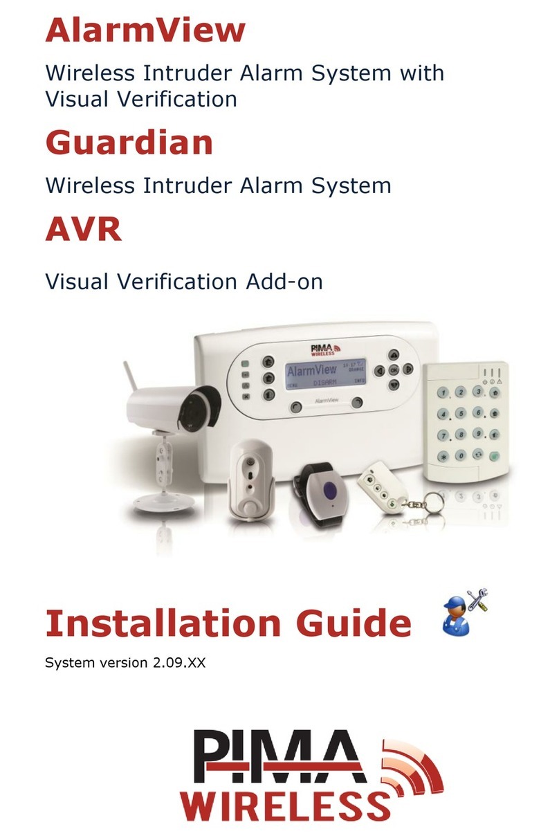
Pima Wireless AlarmView User manual

Wireless Peripherals
For the AlarmView & Guardian Wireless
Intruder Alarm Systems
Installation Guide


1
Table of contents
1SmartView PIR/Camera......... 3
1.1 Features and mode of operation .. 3
1.2 Specs...................................... 4
1.3 Quick Reference........................ 4
1.4 Installation guidelines................ 5
1.5 Replacing the battery ................ 6
2OutView Outdoor Camera....... 7
2.1 Features .................................. 7
2.2 Quick reference guide ................ 7
2.3 Specs...................................... 7
2.4 Installation............................... 8
2.4.1 Opening the camera .......... 8
2.4.2 Connecting to power supply 9
2.4.3 Connecting external trigger. 9
2.4.4 Closing the camera............ 9
2.5 Mounting the camera................. 9
3PIR Detectors....................... 10
3.1 PIR-S & PIR-P (pet-immune)......10
3.2 Features and Specifications .......10
3.3 Quick reference .......................11
3.3.1 Setting the detector’s
sensitivity ..................11
3.4 Enrollment ..............................11
3.5 Mounting ................................12
3.5.1 On a flat surface ..............12
3.5.2 Corner mounting ..............12
3.6 Test .......................................12
4TD-5 Temperature Detector . 13
4.1 Features and Specifications .......13
5DCM Magnetic Door Contact . 14
5.1 Features and Specifications .......14
5.2 Quick reference .......................15
5.3 Enrollment ..............................15
5.4 Installation..............................16
5.5 Using the extension terminal .....16
5.6 Test .......................................17
6KF-1/2 Keyfobs.................... 18
6.1 Features and specifications........18
6.2 Quick reference .......................18
6.3 Enrollment ..............................19
6.4 Replacing the keyfob's battery ...19
7RWK Keypad ........................ 20
7.1 Features and Specifications .......20
7.2 Quick reference .......................20
7.3 Enrollment ..............................20
7.3.1 Mounting the keypad ........ 21
7.3.2 LED indicators ................. 21
7.4 Operating the keypad ............... 21
7.4.1 Alarm key combinations .... 21
7.5 Replacing the battery ............... 21
7.6 Test mode .............................. 22
7.6.1 Keypad function control .... 22
7.6.2 Changing the PIN code...... 22
8SM Smoke Detector ............. 23
8.1 Features and specifications........ 23
8.2 Quick reference ....................... 23
8.3 Calibration & enrollment ........... 24
8.4 Installation ............................. 25
8.5 Test....................................... 25
8.6 Smoke detection...................... 25
8.7 Alarm silence .......................... 26
8.8 Taking new reference value ....... 26
9DCO Carbon Monoxide
Detector .............................. 27
9.1 Features and specifications........ 27
9.1.1 Batteries......................... 28
9.2 Quick reference ....................... 28
9.3 Installation ............................. 28
9.3.1 Guidelines....................... 28
9.3.2 Instructions..................... 29
9.4 Enrollment.............................. 29
9.5 Test....................................... 29
9.6 CO detection & alarming ........... 29
9.7 Alarm silence .......................... 30
10 REP Repeater....................... 31
10.1 Features and specifications........ 31
10.2 Out of the box......................... 31
10.3 Quick reference ....................... 32
10.3.1 The dip switch ................. 32
10.4 Installation & mounting ............ 33
10.4.1 Mounting ........................ 33
10.5 Power supply .......................... 34
10.5.1 Connecting the adapter..... 34
10.5.2 Rechargeable backup
battery...................... 34
10.6 Test....................................... 34
10.7 Normal operation..................... 34
10.7.1 Signal relay..................... 34
10.7.2 Clear memory ................. 35
11 PCP Panic Pendant/Wrist
Watch .................................. 36
11.1 Features and specifications........ 36

Wireless Peripherals Installation Guide
2
11.2 Enrollment ..............................36
11.3 Use instructions .......................36
12 SIR External Siren................ 37
12.1 Features and specifications........37
12.2 Quick reference .......................38
12.3 Function overview ....................38
12.3.1 Audible performance.........38
12.3.2 Strobe light .....................38
12.3.3 Tamper alarm ..................38
12.4 Installation and enrollment ........38
12.4.1 Audio & visual status
indications .................39
12.5 Replacing the battery ...............39
13 SIR-I Indoor Siren ............... 40
13.1 Features and specifications........40
13.2 Quick reference .......................40
13.2.1 Audible performance......... 40
13.2.2 Tamper alarm.................. 41
13.3 Installation and mounting ......... 41
13.4 Enrollment.............................. 41
13.5 Test....................................... 41
13.6 Replacing the batteries ............. 41
14 WLD Water Leakage
Detector .............................. 42
14.1 Features and specifications........ 42
14.2 Mode of operation .................... 42
14.3 Quick reference ....................... 43
14.3.1 Test/Enrollment button ..... 43
14.3.2 Batteries......................... 43
14.4 Installation ............................. 43
14.5 Enrollment.............................. 44
14.6 Test....................................... 44
Introduction
This guide will describe in details each of the available
PIMA Wireless
Intruder Alarm Systems’
detectors and peripherals.
PIMA Wireless
products are easy to install, plug-n-play, providing
intruder alarm capabilities, with or without visual-verification & optional remote Look-in, with a
built-in GPRS/GSM communication modem.
Suitable for residential and small business applications, the alarm systems present a
comprehensive solution for security and personal safety.

1: SmartView PIR/Camera
3
1SmartView PIR/Camera
SmartView is a wireless digital PIR motion detector, combined with a
VGA high-quality color camera. Used for a wide range of home and
office applications, it is designed for easy installation, with no required
vertical adjustment.
Using an authenticated, two-way, encrypted wireless link, (2.4 GHz, FHSS),
it ensures excellent indoor coverage, allowing the transmission of high-
quality color-VGA images, utilizing low power technology.
Figure 1. Smart
View PIR/Camera
The SmartView has a unique technology - Rapid Image Acquisition, for supplying the Visual
images. It also includes a diagonal lens with 11 lenses that enables covering of 22 zones,
delivering uniform detection sensitivity to a range of up to 7 meters.
The SmartView unique feature of “Matched field-of view”, between camera and detector,
allows simple installation at any place in the premises, knowing that the area covered by the
camera is also the protected area, and there is no need for adjustment or alignment of the
detector or camera.
The PIR’s camera takes 3 images upon alarm event - pre-alarm, alarm and post-alarm.
The SmartView reports the following events: Alarm,Low Battery, Supervision and Tamper.
1.1 Features and mode of operation
Detection range: 7 meters, dual Pyro element
VGA CMOS camera, JPEG, 320 x 240, below 15KB/image
1 image is taken upon remote look-in request
Flash, for low-light conditions: 3-4 meters
2.4GHz FHSS, 2-way supervised
Batteries: 2 x Alkaline AA
Figure 2. Dtection range

Wireless Peripherals Installation Guide
4
1.2 Specs
Technical
PIR Lens type
PIR Fresnel, Spherical hard lens
Detection Method
Dual-element PIR with advanced Digital Signal Processing (DSP)
Field of view
62°
Max. Coverage
7 meters
Horizontal adjustment
± 20º left and right
Vertical adjustment
Not required
Camera type
VGA CMOS Color Camera
Visual Type
JPEG, 320X240, 15Kbyte per image
Electrical
Power supply
2 x 1.5V AA (“Energizer” Lithium e 2 L91 recommended)
Power supply
Current Consumption: Standby: 40µA, Transmission: 160mA
Battery life expectancy
3 years (typical usage)
LED
Blue
RF transmission
Frequency
2.4 GHz ISM band
Modulation Type
Frequency hopping spread spectrum (FHSS)
Supervision transmission
2 way radio link 20 Seconds
Transmitted events
Alarm, Image, Low Battery, Supervision, Tamper
Secured Wireless Network
Unique ID serial number - 48 bit
Built-in security using a link key (prevents unauthorized access)
Data encryption (up to 48-bit)
Range
Up to 100 meters, indoor
Physical attributes
Dimensions
82 x 40 x 32 mm
Weight
With Battery: 80 grams
Without battery: 50 grams
Casing
Plastic - PC/ABC 94/VO
Environmental specifications
Operating Environment
Indoor use
Operating temperature
0ºC - 49ºC
Humidity
0 to 85%, non condensed
RFI Protection
>20 V/m up to 1000 MHz
1.3 Quick Reference
Figure 3. SmartView overview

1: SmartView PIR/Camera
5
1.4 Installation guidelines
The SmartView is designed for easy installation. Only a few steps are required to install the PIR
device. To minimize false alarms and ensure better performance, follow these guidelines:
Do not install facing a window or expose to direct sun light, this heat energy may cause
false alarms.
Keep away from electrical power cables, and large metal objects to ensure optimal range.
Do not expose to air drafts or place near air ducts, ovens or radiators as this may cause
false detection.
Do not install behind partitions, plants, curtains etc.
Mount on a solid, stable surface.
When you are sure of the mounting location, follow the steps below to mount the unit on a flat
surface or in a corner:
1. Release the screw fastening the bracket to the detector and
separate the bracket from the detector.
2. Place the bracket up to 2.4 meters from the ground, either on a flat
surface or in a corner.
3. Drill holes using the bracket’s mounting holes and secure the
bracket onto the wall.
4. Remove the battery protective strip.
5. Snap the detector into the mounting bracket and fasten the screw lightly.
6. Rotate the detector horizontally, to face the desired direction and
secure the screw tightly.

Wireless Peripherals Installation Guide
6
1.5 Replacing the battery
When the time comes to replace the batteries in the SmartView, follow these steps.
1. Release the screw fastening the bracket to the detector and separate the bracket from the
detector.
2. Remove the screw fastening the battery compartment
cover to the detector and remove the cover.
Figure 4. Replacing the battery
3. Replace the two batteries with a fresh set (see sticker on the battery holder compartment for
correct polarity).
4. The blue indication LED will light up for between 2 and 4 seconds and then go OFF,
indicating the batteries are installed correctly.
5. Close the battery compartment cover and fasten the screw.

2: OutView Outdoor Camera
7
2OutView Outdoor Camera
The OutView camera is designed for outdoor installations. It utilizes external
trigger input, making it an ultimate solution for enhanced perimeter protection,
as well as a variety of other applications.
Detectors, doorbells, electronic gates, or any other dry contact device can be
used to trigger the OutView camera.
2.1 Features
Figure 5. The
OutView camera
Still image camera
Flash, for low-light conditions: 5 meters
Operating temperatures: -20 to +60 °C
Water resistant
Sun-light protected
2.4Ghz FHSS, 2-way supervised
External transformer: 12VDC/2A
2.2 Quick reference guide
Figure 6. The OutView parts
2.3 Specs
General
Trigger
Wired Trigger, NO or NC
Field Of View
67°
Max coverage
7 meters
Adjustment
Mounting bracket with swivel
(for Pan & Tilt adjustment)
Camera type
VGA CMOS Color Camera
Visual type
JPEG, 320 x 240, 15 Kb per image

Wireless Peripherals Installation Guide
8
Electrical Characteristics
Power supply
External 12Vdc transformer/>1.5A
Current Consumption
Standby: 40 mA
Transmission: 160 mA
Flash pick current:1500mA
Flashlight Type
Visible light strobe
Flashlight Effective Range
Up to 7 meters
RF Transmission Characteristics
Frequency
2.4 GHz ISM band
Modulation Type
Frequency hopping spread spectrum(FHSS)
Supervision transmission
2 way radio link 20 Seconds
Event Transmission
Alarm, Image, Low Battery, Supervision, Tamper
Secured Wireless Network
Unique ID serial number - 48 bit
Built-in security using a link key (prevents unauthorized access)
Data encryption (up to 48-bit)
Range
Up to 100 meters from Camera to Control panel
1
Physical Attributes
Dimensions
125 X 65 mm
Weight
With bracket: 443 grams
Without bracket: 330 grams
Casing
Aluminum
Environmental Data
Operating environment:
Outdoor use, IP 65
Operating temperature:
-10ºC - 49ºC
Humidity:
0 to 85%, non-condensing
RFI Protection:
>20 V/m up to 1000 MHz
2.4 Installation
2.4.1 Opening the camera
1. Remove the camera hood, by holding it firmly and pulling it upwards.
2. Unscrew the front cover.
3. The internal plastic PCB holder is connected to grounding wire inside
the camera. Carefully pull outward the PCB holder with the camera
electronic board, so the grounding wire is left connected.
1Range might be impacted by building materials and interferences

2: OutView Outdoor Camera
9
2.4.2 Connecting to power supply
1. Unscrew the rear seal screw and remove the black rubber seal.
2. Insert power supply wires through the screw and the rubber-seal,
into the camera.
3. Connect the power supply wires to the 12VDC (+) and (-) terminals,
correctly; see the diagram.
The power supply provided with the OutView, may use
also to power the external trigger sensors. However,
caution must be made not to exceed the power output of
the transformer.
2.4.3 Connecting external trigger
1. Connect the external trigger’s wires to the appropriate terminals:
N.O. (Normally Open) or N.C. (Normally Close), and COM.
2. Connect the trigger jumper between the appropriate pins,
according to the installation selected and the printed labels: N.C.
(left) or N.O. (right).
2.4.4 Closing the camera
1. Insert the plastic PCB holder back to its original position inside the OutView housing.
2. Place back the rubber seal and close the seal screw.
3. Close the OutView front cover and place back the hood.
2.5 Mounting the camera
1. Place and mount the camera’s bracket, using 3 dowels & 3 screws.
2. Rotate the bracket’s plastic knob clockwise to its lower position.
3. Connect the camera housing to the bracket; rotate the entire
camera housing around the bracket, then tighten the plastic knob.
4. Adjust the angle of the camera, using Allen key to tighten the
bracket’s tilt screws.
N.C. COM N.O.
12V Power supply
12VDC
-+
N.C.
COM N.O.
Jumper N.C./N.O.
N.C. COM N.O. 12VDC
-+

Wireless Peripherals Installation Guide
10
3PIR Detectors
Passive Infra-Red (PIR) motion detectors are the most frequently used type of detector. There are
two models: normal detector and with Pet immune.
3.1 PIR-S & PIR-P (pet-immune)
The wireless PIR detectors utilize a digitalized adaptive signal processor
algorithm. They are made up of a cover and a base: the cover contains the
electronics and optics; the base has knockouts to allow mounting on flat
surfaces or in a corner situation (using a triangular bracket).
The detectors are designed to give a typical detection range of 12 meters,
when mounted at 2 meters above ground.
Figure 7. Wireless
PIR detector
The PIR-P pet-immune detector eliminates false alarms caused by pets. It is designed not initiate
the alarm when detecting a dog weighing up to 27Kg, few cats, etc.
3.2 Features and Specifications
Microprocessor controlled with advanced Digitalized Adaptive Signal Processor algorithm
Temperature compensated sensitivity control
Insect and draft proof
Detection Range: 12 meters at 90° angle
Surface and Corner mounting with tamper protection
Powered by a pre-inserted lithium battery for easy installation
Low battery detection
Insect and draft proof
Compact & low profile
LED: Fault & Test mode indicator
Range: Over 300 meters in open space2
Operating Temperature: -20°C ~ +50°C
Humidity: Up to 95%, non-condensing
RF Frequency: 868 MHZ Narrow FM
Battery: 1 x Lithium AA, up to 5 years Battery Life3
2Range might be impacted by building materials and interferences.
3Battery life is calculated with averagely 20 activations per day.

3: PIR Detectors
11
3.3 Quick reference
1. LED Indicator and Test button: in normal operation mode, the LED indicator
will not light, except in the following situations:
When the battery is low, the LED will flash for two seconds
upon detection.
The LED will light up for two seconds, when transmitting a
Tamper signal.
If the Tamper is not resolved, the LED will light up upon detection
of movement.
When in Test mode, the LED will light up upon detection of movement.
2. Battery insulator
3. Tamper switch
4. Corner mounting bracket
3.3.1 Setting the detector’s sensitivity
A jumper (JP3) on the detector’s board can be used to set the detection’s sensitivity between
“High” and “Normal”:
1. PIR-S: by default, the detector’s sensitivity is set to “Normal” - the jumper is OFF. If a “High”
sensitivity is required, put the jumper ON.
2. PIR-P: by default, the detector’s sensitivity is set to “High” - the jumper is ON. If a “Normal”
sensitivity is required, put the jumper OFF.
3.4 Enrollment
To enroll the PIR Detector:
1. Remove the battery protective strip. The LED indicator steadily flashes for 30 seconds (the PIR
is warming up). During the warming period, the PIR will not be activated. It is recommended
that you stay away from the detection area during this time. After the warming period is over,
the light will turn off and the PIR will be ready for operation.
2. In the AlarmView or Guardian alarm systems, access the Installer
menu and select
Programming Zones/Peripherals Zones Zone 1-24 Device ID.
3. Press the Test button on the detector’s front cover and follow the enrollment process. Once
completed, the devices serial number will be registered in the alarm system.
4. After the PIR is enrolled, hold it in the desired location and press the Test button to confirm
this location is within signal range of the Control panel.
5. When you are satisfied with your chosen location, proceed with the installation.

Wireless Peripherals Installation Guide
12
3.5 Mounting
The PIR is designed to be mounted on either a flat surface or a corner, with the screws and wall
plugs provided. For corner mounting, use the triangular bracket to provide back tamper protection.
3.5.1 On a flat surface
1. Unscrew the unit and remove the front cover.
2. Remove the appropriate knockouts on the base.
3. Using the holes as a template, drill holes in the surface,
and insert the wall plugs.
4. Screw the base into the wall plugs.
5. Close the unit and screw the cover back onto its base.
3.5.2 Corner mounting
1. Remove the two knockouts on the triangular bracket.
2. Using the two holes as a template, drill holes in the surface of the corner and insert the
wall plugs.
3. Screw the triangular bracket into the wall plugs with the two pointing sticks on top facing you.
4. Fit the PIR onto the hooks of the triangular bracket.
3.6 Test
The detector can be put into Test mode, by pressing its LED. In Test mode, the power consumption
timer will be turned off and the LED indicator will flash every time a movement is detected.
Each time the Test Button is pressed, it enters the test mode for 3 minutes, during which the unit
will transmit a test signal to the Control panel for radio range test.
After 3 minutes it will exit Test Mode automatically and return to normal mode.

4: TD-5 Temperature Detector
13
4TD-5 Temperature Detector
This wireless temperature detector generates an alarm signal,
whenever its surrounding temperature drops down to 5ºC.
The detector also generates periodic tests at intervals of 30
minutes. If no transmission is received, a sensor out-of-order
fault message is generated.
Figure 8. Temperature detector
4.1 Features and Specifications
Excellent stability with high sensitivity
Compact & slim design
Low Battery detection
Powered by pre-inserted Lithium battery
LED: transmission indicator
Optional: built-in sensor or with extended 2m cable
Power: 1 X Lithium 1/2 AA batteries
Battery life: 3 years or over4
Radio frequency: 868 MHz FM
Range: depending on the frequency, 200-300 meters in open space5
Operating temperature: -10° to 50°C
Humidity: up to 95%, non-condensing
Dimensions: 103 X 31 X x 21 mm
4Battery life is calculated at an average of 50 activations per day
5Range might be impacted by building materials and interferences

Wireless Peripherals Installation Guide
14
5DCM Magnetic Door Contact
The wireless magnetic door contact detects opening and closing of
doors and windows. Typically, the door contact is fixed to the
doorframe/windowsill and the magnet is fixed to the door or window.
The door contact consists of a two-part design, made up of a cover
and base. The cover contains all the electronics and the base provides
a means of fixing. A tamper switch protects the enclosure from being
opened, or being removed from the mounting surface.
The door contact can serve as a universal transmitter, with a built-in
terminal block that enables to connect additional magnet switch or
any dry contact N.C. device
Figure 9.Wireless magnetic
door contact
5.1 Features and Specifications
Compact & slim design for easy mounting on door frames
Tamper protection
Randomized supervision signals for trouble-free system integrity checking
Low battery detection
Built-in auxiliary input terminal for wired detectors
Built-in reed switch and external contact can be used simultaneously
Powerful magnet, up to 30mm space between the door contact and magnet
LED: fault & test mode indicator
Complied with CE & UL requirements
Battery: 1 x Lithium 1/2aa
Up to 4 years battery life6
RF frequency - 868 MHZ narrow FM
Range: depending on the frequency, 200-300 meters in open space7
Dimension 103 x 31 x 21 mm
Operating temperature: -20°c ~ +50°c
Humidity: up to 95%, non-condensing
6Battery life is calculated with averagely 20 activations per day.
7Range might be impacted by building materials and interferences

5: DCM Magnetic Door Contact
15
5.2 Quick reference
1. LED Indicator: it lights in the following situations:
When the battery is low, upon activation
When transmitting a tamper signal
When the tamper is open, upon activation
When in Test mode, the LED will flash upon activation
2. Enrollment/Test button
3. Tamper switch
4. Terminal block - for connecting additional magnet switch or
any dry contact N.C. device.
5. J1 Test/Normal mode jumper:
a. Jumper ON: Test mode
b. Jumper OFF: Normal mode (default)
6. JP2 magnet switch bypass jumper:
a. Jumper ON: the internal magnet switch is bypassed: only external device connected
to the terminal block will activate the door contact.
b. Jumper OFF: the internal magnet switch is active (factory default)
5.3 Enrollment
To enroll the door contact:
1. Loosen the screw at the bottom of the plastic cover and remove the cover.
2. Insert the battery into the battery holder, taking care to connect the polarity correctly. The
LED indicator will flash briefly as the unit warms up.
3. Wait for 10 seconds.
4. Access the Installer
menu and select Programming Zones/Peripherals Zones
Zone X Device ID.
5. Press the Test button inside the door contact and follow the enrollment process. Once
completed, the devices serial number will be registered in the AlarmView system.
6. Access the Installer menu and select Service Tests Zone.
7. Insert jumper J1 in place.
8. Hold the door contact in its desired location and press the Test button to confirm that the
location is within signal range of the Control panel.
9. When done, remove jumper J1, close the door contact’s cover and tighten the screw.

Wireless Peripherals Installation Guide
16
5.4 Installation
There are two ways to mount the door contact: self-adhesive or
screw mounting. To install the door contact magnet:
1. Fit the base on the door frame using either the double sided
adhesive pad or the screws provided
2. Fit the magnet on the door using the small double sided
adhesive pad or the screws provided. Align the magnet by the
arrow as shown.
3. Fix the cover assembly onto its base and secure with the screw.
4. Test the door contact (see the previous section on how-to.
remember to remove J1 before closing back the door contact).
5. Screw the cover back onto its base.
The magnet should be no more than 30mm away from the detector, when the
door/window is closed.
Ensure the tamper switch spring is positioned so that it makes contact with the
mounting surface through the tamper switch aperture.
Windows can be protected in a similar way to doors. When fitting to a window,
fix the magnet to the moving part, and the door switch to the frame.
Do not use the adhesive pad , on a surface with peeling or cracked paint, or on
a rough surface.
5.5 Using the extension terminal
The extension terminal enhances installation flexibility. It is most useful in the following cases:
1. If the door contact cannot be mounted on the door frame,
you can connect an additional magnet switch to the
extension terminal and mount the door contact remotely.
2. If more than one window or door need to be protected by
one door contact. In this case, the switches must be wired
to the auxiliary terminal block in series, as shown.
3. If other N.C. dry contact devices, such as broken glass and
smoke detectors are to be used. The devices can be
connected to the extension terminal, so the door contact
will serve as a universal transmitter: the extension terminal
form a closed loop with the device connected to it - when
the device is triggered, the door contact is activated. The
device connected to the extension terminal is in series with
the internal magnet switch.

5: DCM Magnetic Door Contact
17
When used as an extension terminal alone, the internal magnet switch can be bypassed. If the
internal magnet switch is used together with the extension terminal work, then when the
protected door is being opened or the entry device is triggered, the door contact is activated and
will transmit a violation signal; however, the door contact will transmit a door closed or restored
signal only after the protected door and the violated device being restored.
5.6 Test
To test the door contact:
1. Unscrew the unit and remove the front cover.
2. Put the Test/Normal JP1 jumper on.
3. Press the test button.
4. When the test is complete, remove the jumper.
5. Screw the cover back onto its base.

Wireless Peripherals Installation Guide
18
6KF-1/2 Keyfobs
The remote control key fob offers the convenience of arming and disarming
the alarm system at a distance. The keyfob has two models:
KF-1: one-way keyfob.
KF-2: two-way keyfob –every successful operation is indicated in the
key fob by a beep.
6.1 Features and specifications
Figure 10.Remote
control keyfob
4 buttons: Arm Away/Arm Part/Arm Home/Disarm
Water resistance (IP-41)
Transmission LED indicator
Low battery detection
Battery: 1 x Lithium CR2032, Up to 5 years Battery Life8
RF Frequency - 868 MHZ Narrow FM
Range: Over 300 meters in open space9
Dimension 65 X 38 X 15 mm
Operating Temperature: -20°C ~ +50°C
Humidity: Up to 95%, non-condensing
6.2 Quick reference
Figure 11.Arming/Disarming buttons
Figure 12.Back side
Figure 13.Panic alarm
Pressing an arming button causes the alarm system to arm to the respective mode.
Pressing the Disarm buttons causes the alarm system to disarm. If the alarm is sounding, pressing
this button will stop the siren.
Pressing the Full arm and Disarm buttons simultaneously for 1 second generates a Panic alarm10.
8Battery life is calculated with averagely 4 activations per day
9Range might be impacted by building materials and interferences
Other manuals for AlarmView
3
This manual suits for next models
1
Table of contents
Other Pima Wireless Security System manuals