Pima Wireless AlarmView User manual

AlarmView
Wireless Intruder Alarm System with
Visual Verification
Guardian
Wireless Intruder Alarm System
AVR
Visual Verification Add-on
Installation Guide
System version 2.09.XX


Table of contents
1
Table of contents
1Introduction........................................................................................... 5
1.1 Features ..................................................................................................... 5
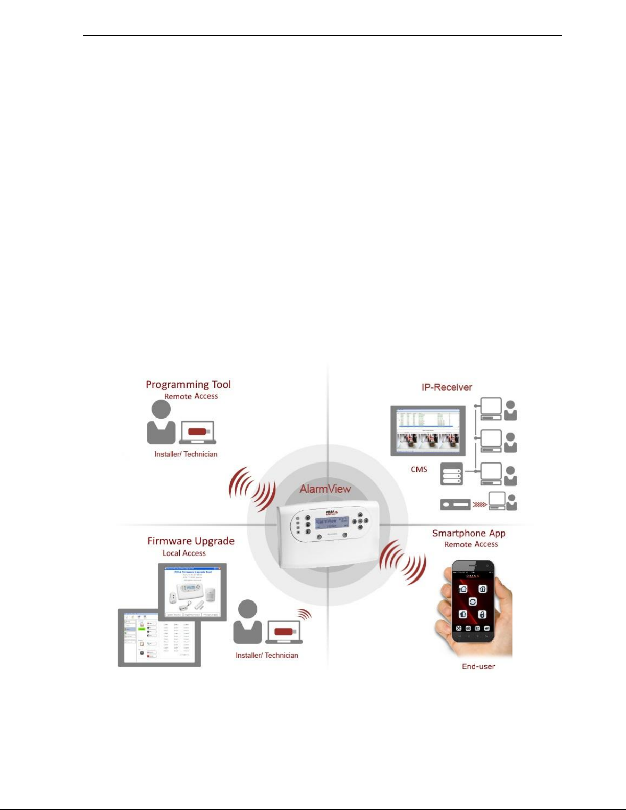
1.1.1 The AlarmView system ............................................................................... 5
1.2 The Guardian system.................................................................................... 6
1.3 The AVR Visual Add-on ................................................................................. 7
1.4 Technical specifications ................................................................................. 8
2Quick Reference Guide ......................................................................... 10
2.1 System components ................................................................................... 10
2.2 The Control Panel....................................................................................... 10
2.2.1 The buttons ............................................................................................ 11
2.2.2 The display............................................................................................. 12
2.2.3 Sound indications .................................................................................... 12
2.2.4 LED indications ....................................................................................... 13
2.2.5 The INFO screen...................................................................................... 13
3System Installation.............................................................................. 14
3.1 General guidelines...................................................................................... 14
3.2 Quick installation ....................................................................................... 14
3.3 Professional mounting................................................................................. 16
3.4 Other installation options ............................................................................ 20
3.4.1 Standalone wired siren ............................................................................. 20
3.4.2 How to use the trigger inputs .................................................................... 20
3.4.3 The AVR................................................................................................. 21
3.4.4 External antenna ..................................................................................... 22
3.5 How to confirm system installation ............................................................... 22
4Setup and Programming ...................................................................... 23
4.1 The Installer’s menu map............................................................................ 23
4.2 Accessing the menus .................................................................................. 24
4.3 The Master and Installer passwords .............................................................. 24
4.3.1 How to reset the passwords to factory defaults ............................................ 24
5Options menu....................................................................................... 25
5.1 Global Settings .......................................................................................... 25
5.2 Zone bypass.............................................................................................. 25
5.3 Contacts ................................................................................................... 25
6Event Log menu ................................................................................... 26
6.1 Log entry examples .................................................................................... 26
7Service menu ....................................................................................... 27
7.1 Tests........................................................................................................ 27
7.1.1 Zones .................................................................................................... 27
7.1.2 External Siren ......................................................................................... 28
7.1.3 Built-in siren........................................................................................... 29
7.1.4 Communication ....................................................................................... 29
7.1.5 System self-test ...................................................................................... 29
7.2 Display version .......................................................................................... 30
7.3 System reset............................................................................................. 30
8Passwords Menu .................................................................................. 31
8.1 Installer.................................................................................................... 31
8.1.1 Access mode........................................................................................... 31
9Set Clock menu .................................................................................... 32
9.1 Time ........................................................................................................ 32
9.2 Date ........................................................................................................ 32
10 Programming menu ............................................................................. 33

Wireless Alarm Systems Installation Guide
2
10.1 Zones/Peripherals ...................................................................................... 33
10.1.1 Zones .................................................................................................... 33
10.1.2 Visual zones (AlarmView and AVR only) ...................................................... 34
10.1.3 Keyfobs/keypads ..................................................................................... 35
10.1.4 Panic button ........................................................................................... 36
10.1.5 External siren ......................................................................................... 36
10.1.6 Built-in siren........................................................................................... 37
10.2 Contacts ................................................................................................... 37
10.2.1 System name ......................................................................................... 37
10.2.2 Contact 1-6 ............................................................................................ 37
10.3 CMS contacts ............................................................................................ 38
10.4 Communication.......................................................................................... 40
10.5 System options.......................................................................................... 41
10.5.1 Entry/Exit delay ...................................................................................... 41
10.5.2 Arm/Disarm............................................................................................ 42
10.5.3 PGM output ............................................................................................ 43
10.5.4 Trigger inputs ......................................................................................... 43
10.5.5 Remote access ........................................................................................ 44
10.6 Factory defaults ......................................................................................... 44
10.6.1 Return to defaults.................................................................................... 45
10.6.2 Clear Passwords ...................................................................................... 45
10.6.3 Clear zones ............................................................................................ 45
10.6.4 Initialize all............................................................................................. 46
10.7 Local programming .................................................................................... 46
10.8 Firmware upgrade ...................................................................................... 46
11 Stop Communication Menu................................................................... 47
12 Operating the Alarm System Remotely ................................................ 48
12.1 By smartphone app .................................................................................... 48
12.2 By text messages....................................................................................... 48
12.2.1 Commands ............................................................................................. 48

Table of contents
3
Appendixes
Appendix A System Peripherals ............................................................... 49
Appendix B The SmartView Detector/ Camera......................................... 50
B.1 How to mount the detector.......................................................................... 50
B.2 How to replace the battery .......................................................................... 50
Appendix C The OutView Camera............................................................. 51
C.1 How to mount the camera ........................................................................... 51
C.2 How to connect the camera ......................................................................... 51
Appendix D External Siren Indications ..................................................... 53
Appendix E Maintenance & Troubleshooting ............................................ 54
E.1 Cleaning the LCD screen ............................................................................. 54
E.2 Replacing the Control Panel’s battery ............................................................ 54
E.3 SIM card icons and LED behavior.................................................................. 54
Appendix F Glossary of terms .................................................................. 55
Appendix G Event Reporting .................................................................... 57
Appendix H SIA and ContactID Codes ...................................................... 59
H.1 Event codes .............................................................................................. 59
H.2 Device number .......................................................................................... 59
H.3 User number ............................................................................................. 59
Appendix I SMS confirmation messages.................................................. 60
Appendix J Limited Warranty .................................................................. 61
Appendix K Declaration of Conformity ..................................................... 62
Figure index
Figure 1. The AlarmView alarm system diagram ................................................................ 5
Figure 2. The Guardian alarm system .............................................................................. 6
Figure 3. The AVR visual Add-on ...................................................................................... 7
Figure 4. The control panel ............................................................................................10
Figure 5. The control panel keys .....................................................................................10
Figure 6. Control panel’s back side ..................................................................................11
Figure 7. The LCD display and buttons.............................................................................12
Figure 8. INFO screen example .......................................................................................13
Figure 9. The back of the circuit’s cradle ..........................................................................17
Figure 10. Wall mounting diagram ....................................................................................18
Figure 11. External siren wiring scheme ............................................................................20
Figure 12. Trigger connections .........................................................................................20
Figure 13. OutView connection diagram.............................................................................52

Wireless Alarm Systems Installation Guide
4
NOTICE AND DISCLAIMER
This guide will help installers and operators in the safe and efficient installation and use of the wireless
systems described herein.
Before trying to install and use the systems, read this guide and become familiar with all safety
requirements and operating procedures.
The system must not be used for purposes other than those for which it was designed.
The use of the software associated with the system is subject to the terms of the license
provided as part of the purchase documents.
PIMA Electronic Systems Ltd.’s exclusive warranty and liability is limited to the warranty and
liability statement provided in this manual and the peripherals guide (P/N 4410399).
This guide describes the maximum configuration of the systems with the maximum number of
functions, including future options. Therefore, not all functions described in this guide may be
available in a specific system.
Warnings are given for situations and circumstances in which a possible hazard can arise.
Cautions are given for situations or circumstances in which the system can possibly be damaged.
Notes are given for situations that need special attention, or to improve the operating procedure.
Wrong operation, or failure of the operator to effectively maintain the system, relieves the
manufacturer (and seller) from all or any responsibility for consequent noncompliance,
damage, or injury.
The text and graphics contained in the guide are for the purpose of illustration and reference
only. In no event shall manufacturer be liable for any special, direct, indirect, incidental,
consequential, exemplary or punitive damages (including, without limitation, any and all
damages from business interruption, loss of profits or revenue, cost of capital or loss of use of
any property or capital or injury).
Graphic signs in this guide
Icon
Description
Caution
Issues that may cause malfunctions
Warning
Issues that may cause damage and actual bodily harm
Note
Important note

Introduction
5
1Introduction
This guide will help you to install PIMA’s Wireless Intruder Alarm Systems: the AlarmView, the
Guardian and the AVR. The three systems are easy to install, plug-n-play, and provide wireless
intruder alarm capabilities, with or without Visual-Verification and optional remote Look-in.
Suitable for residential and small business applications, they present a comprehensive solution for
security and personal safety.
PIMA Wireless products also include a range of various peripherals.
The AlarmView’s unique offering incorporates the SmartView PIR /Camera that combines
movement detection and image capturing, the OutView Wireless camera and a wide range of
regular detectors.
With the Visual Verification, on an alarm event, the cameras transmit both the alarm event and
the images to the control panel, which sends them over GPRS/GSM to the Monitoring Station, and
optionally to the user’s mobile phone or email.
Note that all three alarm systems have two versions: Single SIM, and Dual SIM. Single SIM
systems cannot utilize any of the features of the dual SIM systems.
1.1 Features
1.1.1 The AlarmView system
Figure 1. The AlarmView alarm system diagram
Visual Verification images are sent to the system’s contacts, by MMS and E-mail. See
the AVR section on page 7 for details
Remote Look-in images requests, by text messages from the mobile phones
Remote Upload/Download initiation by the IP Receiver (without SMS)

Wireless Alarm Systems Installation Guide
6
Wireless peripherals including movement/smoke detectors, panic buttons, wireless
keypad, key fobs, door contacts, etc.
“SmartView” detector and camera:
“Matched field-of view” between the detector and the camera, with no dead spots
Flash correction in lowlight
High quality color images
OutView outdoor camera
Double and Backup reporting
Optional dual SIM
End-user notifications by SMS, MMS & E-mail
Alarm reporting options:
ContactID and SIA, via GPRS with SMS back-up
Images via MMS and E-mail
MMS (Multimedia Messaging Service) requires Internet plan and costs money,
including the text messages and emails sent via this service
Remote end-user commands by text messages
Built-in Quad Band GSM/GPRS modem, with SMS as backup
Advanced wireless visual link:
Two way supervised and secured radio network
128-bit encryption key
Supervision report every 10 sec
2.4 GHz FHSS (Frequency Hopping Spread Spectrum) & Diversity receiver (2 antennas)
Supervised 868 MHz link for standard wireless peripherals
Three programmable trigger inputs
PGM output
Graphic, user-friendly menu-driven LCD display
Easy battery replacement
Smartphone applications for controlling the AlarmView
1.2 The Guardian system
The Guardian is a full featured wireless alarm system, designed to
answer the needs of most residential and small office installations.
Based on the AlarmView system, it lacks the Visual capabilities,
including Visual Verification and look-in image options.
The Guardian peripherals are the same as those of the AlarmView,
except visual detectors and cameras.
The Guardian alarm system cannot be upgraded to include the
complete enhanced visual features of the AlarmView system.
Figure 2. The Guardian
alarm system

Introduction
7
1.3 The AVR Visual Add-on
Figure 3. The AVR Visual Add-on
The AVR allows adding Visual Verification capacities to any Intruder Alarm System. Based on the
AlarmView control panel, it is designed for sending Visual Verification and look-in images by up to
six SmartView PIR/Cameras and OutView cameras.
By using trigger inputs and a PGM output, the AVR can do the following:
Be Armed and Disarmed
Trigger the external Alarm System
Serve as a GSM backup communication channel - when triggered by the external Alarm
System (on alarm, for example), the AVR will report the CMS/End-user
The AVR features are:
Six SmartView PIR/Cameras or OutView cameras
Trigger inputs: two for Arming and Disarming, one for communication Backup of the
external alarm system
One PGM output. It can be used for cellular backup of the master system alarm
reporting
Optional dual SIM
Two way communication with the SmartView and OutView
Alarm & image notifications to contacts via MMS/SMS/E-mail
Remote look-in images by contact requests (via SMS)
Remote Upload/Download initiation by the IP Receiver (without SMS)

Wireless Alarm Systems Installation Guide
8
1.4 Technical specifications1
General
Number of zones
Up to 30: 23 wireless, 1 hardwired, 6 visual
Wireless Peripherals
Up to 6 key fob remotes, or keypads
Up to 6 Panic buttons
External siren
Arming modes
AWAY/HOME/PART
Alarm types
Silent, siren or sounder
Built-in siren
Piezoelectric, 85 dBA at 3 m
External siren
1 siren, wireless (indoor/outdoor)
Event log
256 events, non-volatile, with time and date stamp
Codes
8 codes, 4 to 8 digits each (numeric value 1-4):
Master user
4 Regular users (or up to 4 digit code, numeric value 0-9, with
external keypad)
Duress code
Limited 24H code
Installer code
Special functions
Remote control by SMS from one (predefined) mobile phone,
ensuring privacy and security.
Remote Look-in via MMS Local USB connection for setup and
firmware upgrade
I/O
1 PGM output, 3 trigger inputs + trigger #1 can serve as zone #24
Real-time clock
Time and date stamp
Wireless
Advanced wireless link for visual zones
Frequency Band
2.4 GHz ISM band
TX Power
Up to 100 mW
Transmission method
2-way communication
GFSK
Frequency Hopping Spread Spectrum (FHSS)
Supervision
Up to 20 seconds
Secured wireless
network
48-bit factory set ID code
Built-in security using a link key (prevents unauthorized
access)
Data encryption (up to 48-bit)
Expected range2
Up to 100 m (outdoors)
Wireless link for standard peripherals
Frequency
868.6375 MHz
Supervision
Randomly, every 20-50 m + on every transmission
Transmission method
FM, narrow band
Expected Range
Up to 100 m outdoor. Can be extended indoors using the RP-15 Repeater
Communication
Modem
Interface
Quad-band GSM/GPRS
Report destinations
CMS Receivers, mobile phones, Email accounts
Reporting formats
SMS/MMS/Email (by SMTP)/GPRS-IP
1The specifications of the detectors and accessories can be found in the peripherals guide (P/N 4410399)
2Range is impacted by building materials and interference

Introduction
9
End user contacts
Reporting options/formats:
GSM/GPRS, SMS/MMS/Email (via mms) notifications
Four cellular phone numbers
Four email accounts
CMS contacts
Reporting options/formats: GSM/GPRS, SMS/MMS/Email (via mms)
notices
Two IP address
Two phone numbers
Two Email accounts
Others
Physical Characters
Casing
Plastic - PC/ABC 94/V0
Environmental Data
Operating temperature
-10ºC - +49ºC
Storage temperature
-25ºC - +70ºC
Humidity
85%, non-condensed
Electrical Data
Power supply
+12VDC/1A
Current drain
100 mA standby, 0.7A peak
Backup battery
+4.8 VDC,
4 x Ni-MH 2 Ah
Weight:
With battery
Without battery
687 gr
577 gr
Dimensions
225 x 138 x 40 mm
The control panel reports on Low Battery condition 9-12 hours after AC loss.
1-4 hours later it will turn off. Overall, the control panel can stay more than
12 hours in standby mode
We recommend using original AC adaptor and backup battery pack
from PIMA Electronic Systems

Wireless Alarm Systems Installation Guide
10
2Quick Reference Guide
2.1 System components
The alarm system consists of the control panel, and depending on the model, wireless zones (23),
one hardwired zone, visual zones (6) and wireless peripherals (up to 36).
The
Control Panel: consists of the main circuitry, GPRS/GSM module, two wireless
transceivers - standard and visual dedicated one.
Figure 4. The
control panel
Visual detectors:
SmartView: high quality, supervised, rapid-acquisition camera, with PIR detector.
OutView: high resistance outdoor camera, with trigger input from external sources, e.g.,
PIR detectors and magnets.
Wireless detectors: the AlarmView system supports a wide range of wireless detectors,
including door contacts, PIR and Pet-immune motion detectors, Smoke detectors, etc.
Sirens: the control panel has a built-in siren. An external wireless siren (with a strobe)
can also be installed.
Keyfobs/keypads: accessories that are used to arm and disarm the AlarmView.
Panic/Medical pendant and wrist watch: accessories that are used to send emergency
and panic signals.
2.2 The Control Panel
The next figures show the control panel’s buttons and parts. The three arming buttons are
disabled in the AVR.
Figure 5. The control panel keys

Quick Reference Guide
11
Figure 6. Control panel’s back side
2.2.1 The buttons
The table below details the buttons of the control panel.
Button
Function
Press to…
AWAY
Arm to AWAY (full) mode
HOME
Arm to HOME mode
PART
Arm to PARTIAL mode
Left
Access the menus, Select and Insert
Right
Display the system’s Status, Cancel and Delete
OK
Confirm, Enter
Up
Scroll, type the characters A-Z, 0-9, #+_!@- space
Down
Left
Scroll, Exit, Back, and the numeral 4
Right
Scroll, Enter, Duplicate previous character, and numeral 2

Wireless Alarm Systems Installation Guide
12
2.2.2 The display
The LCD screen displays the status, the current time, and the cellular provider and reception. See
the following diagram for details.
Figure 7. The LCD display and buttons
2.2.2.1 The icons
The available icons are:
Transmission of SMS message
Low backup battery
GSM reception level
Battery loss
GSM network error
SIM1 active, fault
AC loss
SIM2 fault3
GPRS transmission
SIM1+2 fault3
2.2.3 Sound indications
The table below lists the sounds the Control Panel sounds.
Tones
Sound
Sounded when
♪
Single beep
A key is pressed
♪-♪
Two beeps
A menu timeout occurs –exit to main menu
♪-♪-♪
Three beeps
Successful command or operation
♪-♪-♪-♪…
Continuous beeps
Entry/Exit delay mode
♪--------♪
Long beep
Illegal command or entry refusal
Chime
Chime is activated
3Displayed only in dual SIM systems

Quick Reference Guide
13
2.2.4 LED indications
The table below shows the LED color indicators and their meaning.
LED
Color+ Behavior
Indication
Green
Power on
Blank
Power loss
Blue, blinking
Wireless communication is active
Green, blinking
Cellular connection - OK
Off
No cellular connection
Orange, 3 blinks
Message waiting to be processed
Red
System trouble. See LCD display for further information
White, blinking
Alarm triggered - all arming modes. Blinking will
stop when re-arming, or entering the system log
2.2.5 The INFO screen
The INFO screen shows a grid of all active zones (up to #30, including visual zones, where available)
in several status options. To display it, press the INFO button when the system is disarmed.
Figure 8. INFO screen example
The next table explains the various zone indications. A zone with more than one status toggles
between them, at one second interval.
Status
Description
Zones in the above example
Empty cell
Undefined zone
19, 20, 30
1-30
Defined zone,
Normal mode
1, 2, 4, 6, 7, 9, 10, 12, 17, 18,
21, 24, 25, 27, 29
Open zone
5, 22, 23
T
Zone tamper open
3, 26
B
Bypassed zone
13, 14
Low battery
11
X
Supervision loss
15
Alarm
8, 16, 28
1 2 4 6 7 10
27
17 1812
21 25
T
B X
T
9
B
2924

Wireless Alarm Systems Installation Guide
14
3System Installation
3.1 General guidelines
The control panel should be installed at a location with optimum wireless reception from
the detectors and peripherals.
A convenient location for mains electricity supply and for user operation, near the main
access point is preferable.
For control panels which are operated using remote keypads, the panel can be
concealed inside a cupboard or loft space in a convenient location for mains electricity
supply.
3.2 Quick installation
For quick installation, you can mount the control panel on any flat surface. To do that, do
the following:
1. On the back side, release the crosshead (“Philips”)
screw of the battery compartment and remove the
cover. The battery lies in the compartment, not
connected
2. Connect the battery wires to the socket

System Installation
15
3. Close the compartment and fasten the screw
4. Remove the plastic protector of the connectors
cavity, by applying pressure with a flathead
screwdriver
5. Insert the SIM card(s) to the SIM holder:
a. In single SIM versions, insert the SIM card into the upper slot (labeled “SIM-1 Main”)
b. In dual SIM versions, first insert the backup SIM into the lower slot (labeled “SIM-2
Backup”), and then insert the main SIM into the upper slot (labeled “SIM-1 Main”).
See the next figure
Do not use PIN Code SIM cards
Do not insert SIM cards under power (AC or DC)
6. Plug the AC adapter into its socket, to the left
of the SIM card holder
Do not connect the AC adapter
to power before connecting it
to the control panel
7. Attach the plastic protector back in place and
pass the AC wires through the wires path
8. Connect the AC adapter to power. Wait for
the Power LED to light up and the LCD
screen to show the normal display
9. Ensure good reception of the wireless and GSM communications (see section 7.1.1.2,
on page 28)

Wireless Alarm Systems Installation Guide
16
10.Secure the control panel to the designated surface:
drill two holes, corresponding to the two keyhole
hangers on the back plate (see the image below),
and fasten the supplied screws, leaving a small
space between the screw head and the surface
11.Hang the control panel
3.3 Professional mounting
If the control panel needs to be secured with the tamper protection, do the following steps:
1. Open the cover: insert a small slotted
screwdriver into the two slots at the bottom of
the control panel and apply pressure upwards
2. Lift and remove the front cover

System Installation
17
3. Pull out the plastic cradle of the circuit board,
by pulling its two clips on both sides, and turn
it over
Figure 9. The back of the circuit’s cradle
4. Connect the battery wires to the socket
SIM-1
Main
SIM-2
Backup

Wireless Alarm Systems Installation Guide
18
5. Insert the SIM card(s) to the SIM holder:
a. In single SIM versions, insert the SIM card into the upper slot (labeled “SIM-1 Main”)
b. In dual SIM versions, first insert the backup SIM into the lower slot (labeled “SIM-2
Backup”), and then insert the main SIM into the upper slot (labeled “SIM-1 Main”).
See the previous figure
Do not use PIN Code SIM cards
Do not insert SIM cards under power (AC or DC)
6. On the designated surface, drill holes, corresponding to those marked with arrows on the
next figure and insert drywall plugs into them. Note, that the hole in the middle is designated
for the tamper switch’s knockout4
The tamper switch knockout must be secured with a dedicated screw, to
comply with EN50131-1 regulation
Figure 10.Wall mounting diagram
7. Route the AC adapter’s plug and wires through the wires path. See the next figure.
8. Secure the back plate to the surface with screws.
4When the control panel is forcibly removed from the wall, the knockout breaks and the tamper is activated
195mm
70mm
29mm
Tamper switch
knockout
Other manuals for AlarmView
3
This manual suits for next models
3
Table of contents
Other Pima Wireless Security System manuals
Popular Security System manuals by other brands

Brink's Home Security
Brink's Home Security BHS-2000B owner's manual

Digital Alert Systems
Digital Alert Systems DASDEC-III Hardware installation guide

Klaxon
Klaxon SO4 Series installation instructions

Informa
Informa ADE Gen4 manual

RED SHIELD
RED SHIELD WS500 user guide

Bird-X
Bird-X DEER GARD instruction manual