Pinion P-Line P1.18 User manual

OWNER'S MANUAL

© Pinion GmbH 2018
All rights reserved
Printed in Germany
08-2018
Inhalt:
www.technische-redaktion.de

CONTENTS
3
INTRODUCTION
SYMBOLS.......................................................4
WARNING INSTRUCTIONS ...............................4
FOREWORD ....................................................5
TECHNICAL DATA
DEVELOPMENT...............................................7
TIGHTENING TORQUES ...................................7
SAFETY
INTENDED USE...............................................8
BASIC SAFETY INSTRUCTIONS … ..................8
ON THE ROAD
RUNNING IN THE GEARBOX ..........................10
BEFORE EVERY RIDE ...................................10
SHIFTING CORRECTLY ..................................11
MAINTENANCE
REGULAR MAINTENANCE WORK ...................12
ADJUSTING SHIFTING ...................................14
OIL CHANGE.................................................15
OIL CHANGE DATA ........................................35
INSTALLATION WORK
INSTALLING ROTARY SHIFTER .....................16
INSTALLING OR REPLACING
SHIFTING CABLES .......................................17
INSTALLING PINION CHAIN TENSIONER ........24
ADJUSTING CHAIN TENSION
(PINION CHAIN TENSIONER) ........................25
EXCHANGING PULLEYS
(PINION CHAIN TENSIONER) ........................26
REPLACING CHAIN RING ..............................26
INSTALLING CRANKS ....................................28
CHAIN/TOOTHED BELT
– LENGTH & TENSION .................................29
INSTALLING GEARBOX ..................................30
REMOVING GEARBOX ...................................31
SERVICE
SERVICE VIDEOS ..........................................32
OVERVIEW OF DEALERS ...............................32
TECHNICAL SUPPORT ...................................32
LEGAL INFORMATION
LIABILITY .....................................................33
WARRANTY ..................................................33
OIL CHANGE DATA ........................................35

INTRODUCTION
4
SYMBOLS
This instruction identifies particularly important information and gives
you additional messages or tips.
ÎÎ The arrow prompts you to carry out an action.
•• The dot indicates results or necessary preconditions.
P1.18
Instructions with this indication only relate to the corresponding type of your
Pinion gearbox.
www.pinion.eu The play button draws your attention to a Pinion video on the topic at
https://pinion.eu/en/service-videos/.
For direct access scan the QR code –see SERVICE VIDEOS, page 32.
WARNING INSTRUCTIONS
This instruction warns of a hazardous situation, which if not
avoided can result in death or serious injury.
Ζ ... and shows you how to avoid it.
This instruction warns of a hazardous situation, which if not
avoided can result in minor or moderate injury.
Ζ ... and shows you how to avoid it.
This instruction warns of potential material damage.
Ζ ... and shows you how to avoid it.
This instruction warns of potential environmental
damage.
Ζ ... and shows you how to avoid it.

INTRODUCTION
5
FOREWORD
You are now the owner of a modern Pinion gearbox – made in Germany.
This owner's manual is a part of your Pinion product and contains information on how to operate,
adjust, install and maintain your product safely.
Read this manual carefully before using your Pinion product. Always observe and follow all instruc-
tions in this manual – and also the user instructions from other manufacturers whose products are
used on your bicycle (chain, wheels, quick release skewers etc.).
Remember that the mechanic is responsible for the suitability and compatibility of all components
that interact with your Pinion product.
If the instructions in this manual are not observed, this may result in accidents
with fatal consequences or serious injury.
Keep this manual for other users of your Pinion product. Make sure that every user reads, understands
and observes this manual.
If you ever sell or give away your Pinion product, give this manual to the new owner.
The illustrations in this manual may be different from your Pinion product, but the required work steps
are the same for all gearbox types – unless otherwise specified.
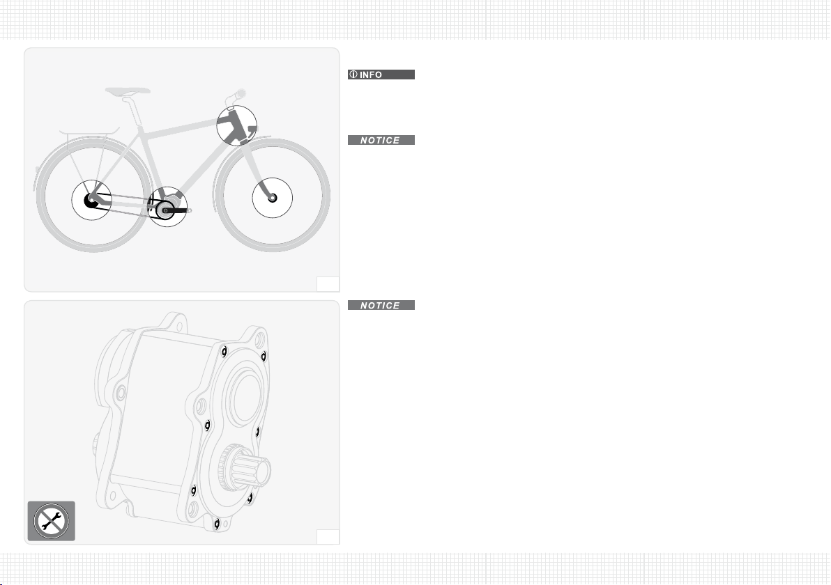
The gearbox type of your Pinion gearbox is stamped on the left side of the gearbox above the cable box
cover – the 6-digit serial number on the edge of case. (fig. 1)
Please note that the transmission will have a different feel compared to a derailleur system.
Familiarize yourself with your new Pinion gearbox and the differences in your transmission during your
initial rides.
See https://pinion.eu for many more tips and more information on your Pinion product.
We wish you all the best with your leisure and competitive riding.
The Pinion Team
1

TECHNICAL DATA
6
Gearbox type P1.18 P1.12 P1.9XR P1.9CR
Chain line (A) – with Pinion chain ring
mm
54*
Pitch circle Ø (B), Pinion spider 104
Q-factor (C)174
Crank length** (D)180 / 175 / 170 / 165 / 160 / 155
Crank axle standard Pinion Standard
Dimension, chain (E)mm 6.6 – 6.8 (9-speed)
Gears via rotary shifter 18 12 9
Gear ratio, total %636 600 568 364
Gear steps, constant ~ 11.5 ~ 17.7 ~ 24.3 ~ 17.5
Ratio in 1st gear 1.82 1.30
Ratio in the fastest gear 0.29 0.30 0.32 0.36
Oil volume/type ml (oz) 60 (2.0) / Pinion
Input torque max. N·m (lbf·in) 250 (2213)
Rider weight max.*** kg (lb) 110 (243)
2
A
C
D
E
* If the Pinion spider is used, the chain line or beltline is defined by the contact surface
(56 mm) of the spider and the dimension/geometry of the chain ring or the belt
sprocket that is used – e.g.: 56 mm + ½ t = 58 mm chain line
(with symmetrical chain ring with thickness t=4 mm).
** optional
*** Rider + backpack etc.
B

TECHNICAL DATA
7
1 2 3 4 5 6 7 8 9 10 11 12 13 14 15 16 17 18
1,3 (4.3) 1,5 (4.9) 1,6 (5.2) 1,8 (5.9) 2,0 (6.6) 2,2 (7.2) 2,5 (8.2) 2,8 (9.2) 3,1 (10.2) 3,4 (11.2) 3,8 (12.5) 4,3 (14.1) 4,8 (15.7) 5,4 (17.7)
6,0 (19.7)
6,6 (21.7)
7,4 (24.3)
8,3 (27.2)
1,0 (3.3)
2,0 (6.6)
3,0 (9.8)
4,0 (13.1)
5,0 (16.4)
6,0 (19.7)
7,0 (23.0)
8,0 (26.2)
9,0 (29.5)
11,5 %
m (ft)
P1.18
3
TIGHTENING TORQUES
Tightening torque in N·m (lbf·in) max.
Gearbox retaining screws 10 (89) with screwlock, medium-strength
Central crank screws 10 (89) with screwlock, medium-strength
Crank clamp screws 10 (89) with SCHNORR® lock washer, dry
Chain ring lock ring 40 (354) dry
Cable box cover housing screws 1.5 (13) dry
Rotary shifter housing clamping screw 2 (18) dry
Rotary shifter cover housing screw 0.4 (4) dry
Shifting cable clamp screws 0.4 (4) dry
Oil drain plug 3 (27) dry
Pinion chain tensioner retaining screws 4 (35) dry
Pulley retaining screws 2 (18) dry
DEVELOPMENT
P1.18
The specified values in m (ft) per crank revolution
correspond to the recommended ratio for sprocket (rear) : chain ring
(front) 26 : 30 = 0.866.
The calculation is based on the tyre size 28×1.4(37-622). (fig. 3)
You can find a convenient program for calculating your individual ratio
as well as the development values of other types of Pinion gearbox at
https://pinion.eu.

SAFETY
8
INTENDED USE
Use other than as intended may cause accidents resulting in death
or serious injury.
Pinion gearboxes are designed and intended exclusively
•·for installation on bicycle frames designed for the purpose with stiff rear triangle
and a corresponding gearbox interface in the area of the bottom bracket.
•·for installation on bicycle frames designed for the purpose with suspension rear
triangle and a corresponding gearbox interface in the area of the bottom bracket
– and, if necessary, in combination with a suitable chain or belt tensioner system
that compensates for the distance between the chain ring and sprocket or between
the belt sprockets that varies with the movement of the suspension.
•·for use with a single-gear rear freewheel rear hub without a back pedal brake*.
•·for use with a rear cassette freewheel rear hub with spacers for setting the correct
chain line.
•·for use with a rear hub with an electric drive motor.
•·for use with a suitable chain or belt tensioner system.
•·for the maximum approved rider weight –see TECHNICAL DATA, page 6.
Pinion gearboxes must never be used in combination with a stiff single gear rear hub!
BASIC SAFETY INSTRUCTIONS …
Always remember that cycling can be dangerous for the rider and other people and also
for the bicycle and its components. Accidents resulting in death or serious injury may
happen even with the best protective equipment and all required safety devices.
Use your common sense and avoid dangerous actions.
* A back pedal brake cannot be used with the freewheel integrated in the gearbox!

SAFETY
9
… FOR INSTALLATION & MAINTENANCE
A gearbox damaged as a result of faulty or non-approved installa-
tion may cause an accident.
Ζ Don't overestimate your technical ability. Have all installation and maintenance
work done by a specialist workshop for bicycles. That is the only way to be sure that
the work is done correctly. For a list of Pinion dealers and specialist workshops,
refer to https://pinion.eu/en/dealer-overview/. For direct access scan the QR code
–see OVERVIEW OF DEALERS, page 32.
Ζ Installation work that is not described in this owner's manual (e.g. opening the
gearbox, retightening the housing screws, etc.) must be done exclusively by a
specialist workshop authorized by Pinion or by the Pinion company itself.
Do not attempt work of this type yourself – you will not only endanger your own
health but you may be exposed to liability claims.
Ζ Never modify your Pinion product in any way (e.g. grinding, drilling, painting, etc.).
Ζ Always use a torque wrench designed for the required torque at installation steps
that require a specific tightening torque.
Ζ Keep your bicycle in good technical condition at all times.
Unsuitable accessories and additional components may cause
accidents.
Ζ Use original Pinion parts and lubricants exclusively.
Ζ Use a rear wheel quick release system that reaches the required closing pressure
of at least 4000 N exclusively. It is best to use a rear hub that is permanently
fastened with axle nuts in the rear triangle, or which has a through axle.
Ζ Use exclusively a bicycle chain with a width of 6.6 – 6.8 mm (9-speed) and an
appropriately sized sprocket, or a toothed belt system approved by Pinion.
… WHEN ON THE ROAD
Component failure may cause accidents.
Ζ Before every ride make sure that the quick release system of your wheels is
correctly installed and that your wheels cannot be accidentally released.
Ζ Before every ride make sure that your brakes are operating correctly and the brake
pads are not excessively worn.
Ζ Before every ride make sure your chain or belt is correctly tensioned.
Ζ Never exceed the maximum approved rider weight –see TECHNICAL DATA, page 6.
Ζ Avoid jumping from a great height – this exposes your Pinion gearbox to very high
load peaks.
Ζ Never ride with your Pinion gearbox if damage (to the gearbox housing, cranks,
etc.) is visible, unusual noises can be heard, or if you have any doubts the condi-
tion of the gearbox. Have your Pinion gearbox checked by a specialist workshop for
bicycles.
For a list of Pinion dealers and specialist workshops, refer to https://pinion.eu/
en/dealer-overview/. For direct access scan the QR code –see OVERVIEW OF DEALERS,
page 32.
Ζ Do not ride with your Pinion gearbox below -20 °C (-4 °F) or above 40 °C (104 °F)
ambient temperature.
Incorrect riding behaviour or improper equipment may cause
accidents.
Ζ Always obey the traffic regulations of the country where you are riding your bicycle
(lights, reflector, etc.) and also the regulations governing off-road mountain biking.
Ζ Always wear a good-quality, undamaged cycling helmet (e.g. ANSI-certified) and
clothing that is close-fitting but does not hinder movement.
Ζ Ride your bicycle only when you are in good physical condition and your bicycle and
all its components are in good condition.

ON THE ROAD
10
RUNNING IN THE GEARBOX
The surfaces of the gears and transmission components are smoothed down over
the first 1000 km of cycling. Following that, the gearbox will run more smoothly – with slick shifting
operations.
Any roughness present in the drive or when shifting gear is normal when your Pinion gearbox is new,
and is nothing to be concerned about!
BEFORE EVERY RIDE
Component failure may cause accidents.
Ζ Before every ride make sure that the quick release system of your wheels is correctly installed and
that your wheels cannot be accidentally released.
Ζ Before every ride make sure that your brakes are operating correctly and the brake pads are not
excessively worn.
Ζ Before every ride make sure your chain or belt is correctly tensioned.
Ζ Never ride with your Pinion gearbox if damage (to the gearbox housing, cranks, etc.) is visible,
unusual noises* can be heard, or if you have any doubts the condition of the gearbox. Have your
Pinion gearbox checked by a specialist workshop for bicycles.
A chain or belt that continues to rotate when the crank is stationary because
the sprocket or belt sprocket and rear hub do not move easily during freewheel may cause an
accident.
Ζ Before every ride make sure that the sprocket or belt sprocket and rear hub freewheel smoothly.
* Cracking or creaking noises when pedalling do not come from the inside of your
Pinion gearbox, but usually originate from a loosened bolted connection – in most cases the noise is
eliminated after tightening the pedals, for example. If not, you can find help in a specialist workshop
for bicycles – they will know about other possible problem areas which can often be resolved with
little effort.

ON THE ROAD
11
4
1
SHIFTING CORRECTLY
The mark (1) on the rotary shifter cover indicates the selected gear.
You can shift through several gears with one movement (e.g. from 06 to 02).
You can shift at a standstill or with the crank rotating backwards and this protects
the gearbox.
Downshifting (18–17–16– … –01) under load is possible to a limited extent.
The shifting operation is not executed if the pressure on the crank or pedal is too high.
A mechanism in the gearbox allows upshifts (01–02– … –18) under load. This is
possible during all gear shifts, except when shifting between each of the sub-units. At these points
the pressure on the pedal must be momentarily released.
ÎÎAlways reduce the pressure on the pedal during downshifts (18–17–16– … –01).
ÎÎ
P1.18
When shifting up from 06 to 07 and from 12 to 13 always reduce the pressure on the pedal.
ÎÎ
P1.12
When shifting up from 04 to 05 and from 08 to 09 always reduce the pressure on the pedal.
ÎÎ
P1.9
XR
P1.9
CR
When shifting up from 03 to 04 and from 06 to 07 always reduce the pressure on the
pedal.
Occasionally it can happen that your crank "drops" by about 10° after a shifting oper-
ation, you feel a short jolt caused when a gear is not engaged directly until the pawl has engaged in
the next tooth. This phenomenon cannot be eliminated, but it does not lead to damage to the gearbox.
MAINTENANCE
12
REGULAR MAINTENANCE WORK
The frequency of use and weather conditions determine the frequency of maintenance
work on your Pinion gearbox.
Carry out the following maintenance operations more frequently if you use your bicycle under extreme
conditions (rain, road grit, dirt, long distances etc.).
Corrosion and material damage by penetration of water.
Ζ Never use a pressure cleaner or steam cleaner to clean your bicycle – the seals in the bicycle
components cannot withstand this pressure.
Ζ Be careful even if you use an ordinary hose. Never direct a spray of water directly at the areas of
a seal. (fig. 5)
5
3 mm
6
Irreparable damage to the gearbox housing or leakage.
Ζ Never tighten or loosen gearbox housing screws. (fig. 6)
Ζ Gearbox housing screws are exclusively allowed to be moved in a specialist workshop authorised
by Pinion, or by Pinion itself.

MAINTENANCE
13
1 In particular in wet conditions or if exposed to road grit. | 2 Alternatively 1× each year. | 3 Or after each ride in wet conditions and if exposed to road grit.
After every ride1every 250 km every 500 km every 10 000 km2
ÎÎClean the gearbox with water, detergent and a brush.
ÎÎClean the chain/belt, chain ring and sprocket or belt sprockets as well as, if neces-
sary, the pulleys of the chain tensioner. 3
ÎÎCheck the chain or belt tension and correct it if necessary
–see CHAIN/TOOTHED BELT – LENGTH & TENSION, page 29.
ÎÎOil the chain lightly. 3
ÎÎCheck that the chain tensioner pulleys move smoothly and inspect for wear (exces-
sive play, loud running noises) – replace pulleys if necessary
–see EXCHANGING PULLEYS (PINION CHAIN TENSIONER), page 26.
ÎÎCheck for wear on shifting cables, shifting cable outer sleeves, chain/belt, chain
ring and sprocket or belt sprockets, renew if necessary.
ÎÎCheck shifting cables for tension and freedom of movement, adjust or renew if
necessary
–see ADJUSTING SHIFTING, page 14.
ÎÎOpen cable box. Thoroughly clean cable pulley, sliding surface and cable box inte-
rior, planetary gears, etc. and grease them liberally –see (fig. 13), page 18.
ÎÎCheck that all screw fasteners – except gearbox housing screws – have the required
tightening torque and adjust if necessary
–see (fig. 6), page 12, –see TIGHTENING TORQUES, page 7.
ÎÎPerform an oil change
–see OIL CHANGE, page 15.

MAINTENANCE
14
7
3
ADJUSTING SHIFTING
Your Pinion gearbox is correctly adjusted if the shifting operation is performed imme-
diately (cable tension), all gears can be selected with minimum force (cable tension) and the display
on the rotary shifter matches the selected gear (synchronization).
ADJUSTING CABLE TENSION
The cable tension is in the correct range if the ends of the shifting cable outer sleeves
are within the stops on the gearbox and rotary shifter housing without play and are not under tension
and it has approx. 2 mm rotary play.
ÎÎUnscrew both adjusting screws ¼ revolution counterclockwise (+).
••Cable tension is increased.
••Force required is increased.
or:
ÎÎScrew in both adjusting screws ¼ revolution clockwise (-).
••Cable tension is reduced.
••Play on the rotary shifter is increased, the shifting operation is less immediate.
SYNCHRONISING ROTARY SHIFTER POSITION
ÎÎShift rotary shifter clockwise (01–02–03– … ) to the stop towards the last position (18 or 12 or
09).
ÎÎCheck that the symbol for the last position (18 or 12 or 09) is centrally placed beside the
mark (1).
ÎÎScrew in adjusting screw (2) ¼ revolution clockwise (-).
Unscrew adjusting screw (3) ¼ revolution counterclockwise (+).
••The rotary shifter scale moves towards position 17 or 11 or 08.
or:
ÎÎUnscrew adjusting screw (2) ¼ revolution counterclockwise (+).
Screw in adjusting screw (3) ¼ revolution clockwise (-).
••The rotary shifter scale moves towards position 01.
ÎÎCheck setting and repeat procedure if necessary
1
2

MAINTENANCE
15
1,5 N·m (13 lbf·in) max.
2,5 mm
8
12
OIL CHANGE www.pinion.eu
Dispose of used lubricants and oils correctly and in accordance
with the applicable regulations – never dispose of waste in the sewage system or in the ground.
Every 10 000 km (6 200 miles) or 1× each year, the oil in your Pinion gearbox must be
changed.
Use original Pinion gearbox oil exclusively. Oil fill volume: 60 ml (2.0 oz).
In the 1st oil change of your Pinion gearbox, the volume of drained oil will be less than
60 ml (2.0 oz) – nevertheless, comply with the fill volume that we specify!
The Pinion oil service-set (P8903) enables you to extract used gearbox oil from the
gearbox quickly and cleanly.
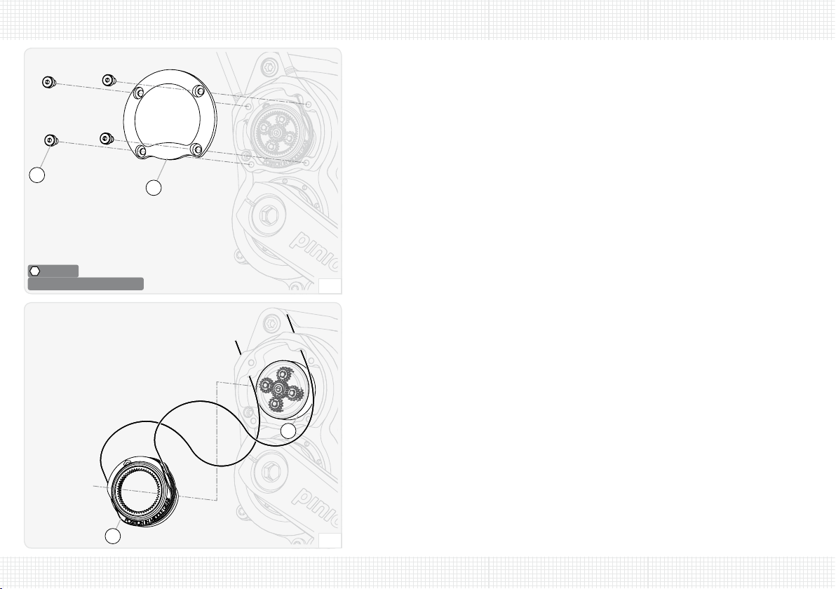
ÎÎUnscrew the housing screws (1) of the cable box cover (2).
ÎÎRemove cable box cover.
3 N·m (27 lbf·in) max.
3 mm
9
3
ÎÎUnscrew the screw plug (3) in the filler opening.
ÎÎHave a drainage tray ready.
ÎÎPlace bicycle on its side.
ÎÎDrain used oil completely from the filler opening into the drainage tray.
ÎÎPlace the bicycle upright or replace on repair stand.
ÎÎAdd fresh oil – oil fill volume: 60 ml (2.0 oz).
ÎÎScrew the screw plug (3) into the filler opening and tighten with a tightening torque of 3 N·m
(27 lbf·in).
ÎÎPut on cable box cover (2).
ÎÎTighten housing screws (1) with a tightening torque of 1.5 N·m (13 lbf·in).
ÎÎEnter oil change date –see OIL CHANGE DATA, page 35.
••The oil change is complete.
INSTALLATION WORK
16
INSTALLING ROTARY SHIFTER www.pinion.eu
Incorrect installation can restrict braking and steering and cause accidents.
Ζ Make sure that the position of the rotary shifter housing does not interfere with the full range of
operation of the brake lever blade.
Ζ Make sure that the shifting cables do not interfere with the handlebar movement.
Incorrectly mounted handlebar can fail and cause an accident.
Ζ Always follow the manufacturer's directions for carbon handlebars.
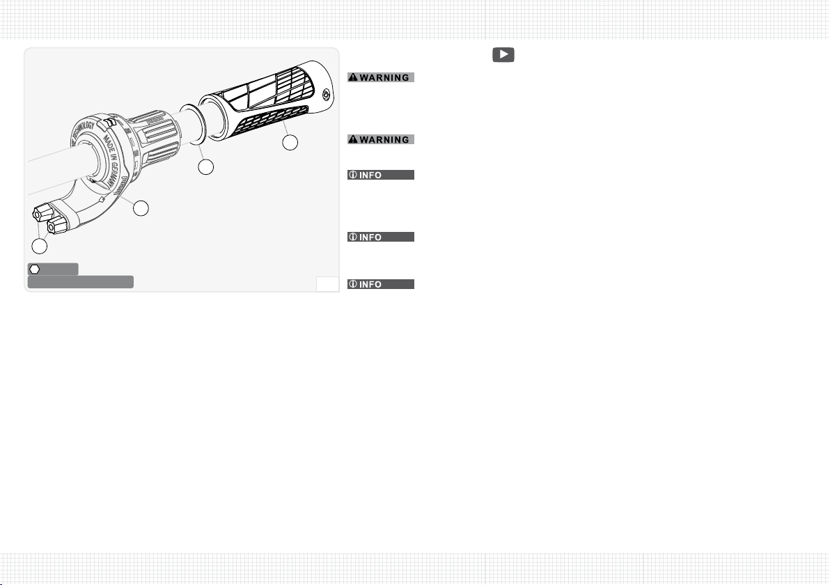
The Pinion rotary shifter housing is generally correctly positioned with the adjusting
screws (1) for the shifting cable pointing down and slightly forward – i.e. in the 4–5 o'clock direction.
In this position you can best see the current gear and the shifting cables do not interfere with the
brake lever blade.
In the event of a fall it is advantageous if the brake lever blade can twist. This reduces
the danger of irreparable damage – including the handlebar. Tighten the clamp screws of the brake
lever blade just tight enough so it cannot be twisted by hand.
You will only need the spacer ring (2) if you are using a handlebar grip which has a
tendency for touching the rotary shifter.
ÎÎUse carbon assembly paste on the clamp area for carbon handlebars.
ÎÎSlide the rotary shifter housing onto the handlebar.
ÎÎSlide handlebar grip (3) and if applicable bar end onto the handlebar.
ÎÎPush rotary shifter housing onto the handle of the handlebar to the stop and rotate to the correct
position.
ÎÎTighten clamping screw (4) with a tightening torque of 2 N·m (18 lbf·in).
ÎÎMake sure that the rotary shifter can be twisted freely – install a spacer ring (2) if necessary.
••The installation of the rotary shifter is complete.
2 N·m (18 lbf·in) max.
2,5 mm
10
4
1
3
2

INSTALLATION WORK
17
INSTALLING OR REPLACING SHIFTING CABLES www.pinion.eu
You operate your Pinion gearbox with 2 shifting cables.
The clamps for the shifting cable ends are in the rotary shifter.
It is essential that you use commercially available shifting cables with dimension Ø1.1–1.25 mm,
nipple 4.4 × 4.4 mm. Genuine Pinion shifting cables guarantee optimum shifting behaviour and can
be ordered from one of the Pinion bicycle dealers.
As a tool for dealing with breakdowns when you are out riding, you will find a bit
(size 1.5 mm/4 mm) inserted inside your rotary shifter (1) – this fits the clamping screws of the cable
clamps. You can use the rotary shifter cover as a tool holder if necessary.
During installation of the shifting cables, you will need to move the sun gear of your
Pinion gearbox, so it is a good idea if the right crank and chain ring are fitted. This makes it much
easier for you to brace the selector shaft.
ÎÎUnscrew housing screw (2) of the rotary shifter cover (3).
ÎÎUnhook rotary shifter cover at top and remove.
1,5 mm 4 mm
0,4 N·m (4 lbf·in) max.
3,5 mm
11
0,4 N·m (4 lbf·in) max.
1,5 mm
12
4
The clamp screws are easily accessible at rotary shifter positions 01 and 18 or
01and12 or 01and09 depending on the type of your Pinion gearbox.
ÎÎSlacken clamp screws (4) – 2× per shifting cable end.
ÎÎPull shifting cables out of the rotary shifter.
ÎÎCut off the spliced-on shifting cable ends with a sharp wire cutter.
ÎÎFirst, screw in adjusting screws (5) completely – then unscrew 3 revolutions.
••This ensures an adequate adjustment range for subsequent adjustments of the transmission.
1
2
3
5
INSTALLATION WORK
18
1,5 N·m (13 lbf·in) max.
2,5 mm
13
67
8
ÎÎRemove the cable pulley (8) with the shifting cables from the cable box.
ÎÎRemove shifting cables from the cable pulley.
ÎÎThoroughly clean the cable pulley.
ÎÎThoroughly clean the cable box interior.
ÎÎThoroughly clean planetary gears and sun gear and grease them liberally.
ÎÎLightly grease sliding surface (9) of the cable pulley.
14
ÎÎUnscrew the housing screws (6) of the cable box cover (7).
ÎÎRemove cable box cover.
9


INSTALLATION WORK
20
18
ÎÎGuide the shifting cables through the outputs of the cable box.
ÎÎKeep the shifting cables taut.
17
Correctly wound up shifting cables will not cross over one another at any point!
ÎÎWind left shifting cable (output 1.) onto cable pulley – 1 ¼ turns.
ÎÎWind right shifting cable (output 2.) onto cable pulley – ¼ turn.
ÎÎHold the shifting cables with the cable pulley with 1 hand so the shifting cables cannot unwind.
This manual suits for next models
3
Table of contents
Other Pinion Bicycle Accessories manuals


