4
Maintenance
Maintenance of your fork is important to your safety and to the useful life
of the fork. Frequent inspection by you and regular professional service
by your Cannondale Dealer can help ensure years of safe/trouble-free
operation.
YOU BEFORE AND AFTER RIDING:
INSPECT - Clean and inspect entire fork for cracks or damage. Things
that can indicate a serious problem: (1) Unusual“klunking”or knocking
noises (2) changes in travel (3) Over-extended or compressed boot (4)
Changes in the way the fork has been working (5) Loss of adjustments
features. (6). Sudden air loss or leaking uid.
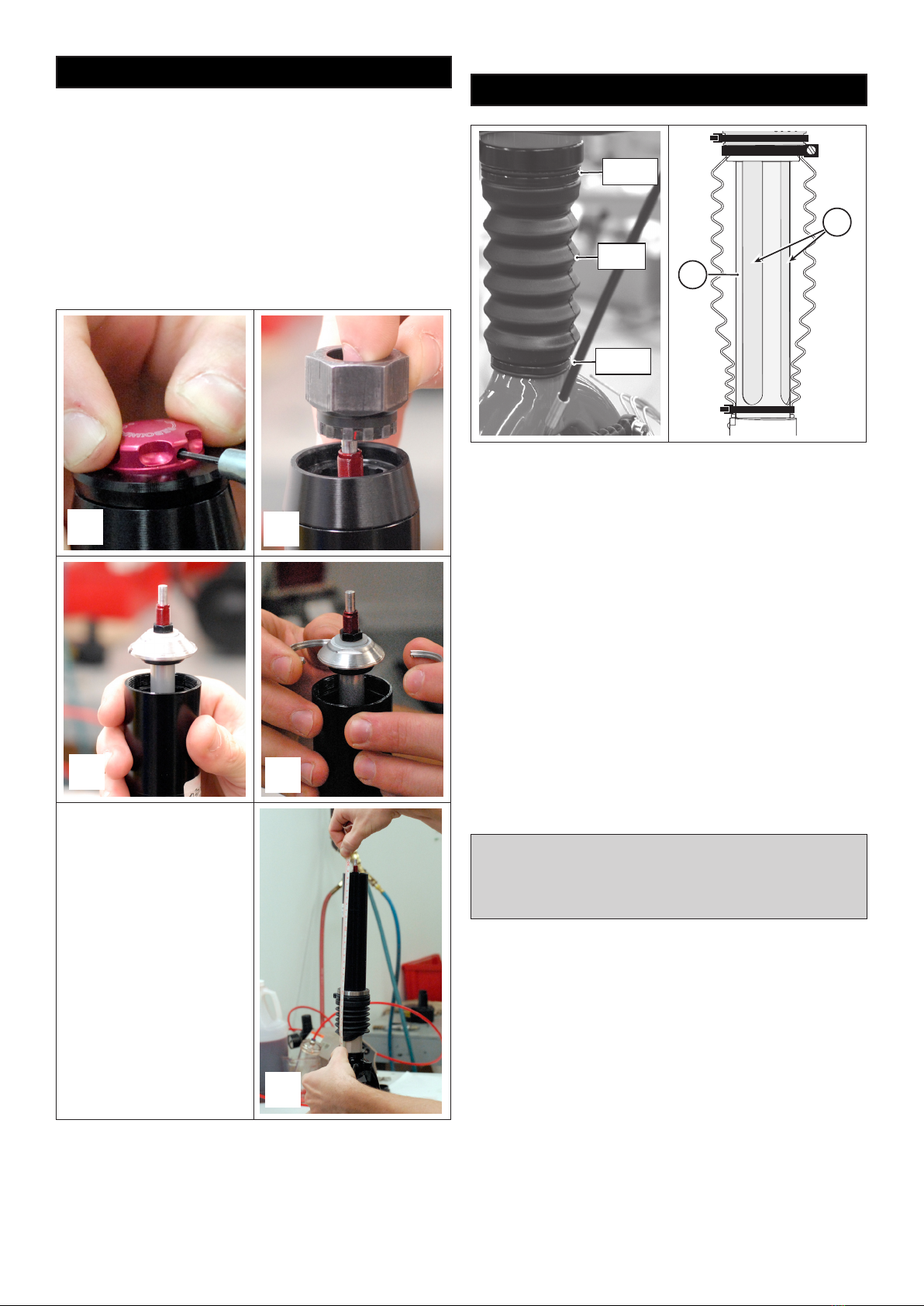
Check the fork boot for damage cracking, splits, or tears. Be sure to check
in the folds of the boot. Check for any cables or lines rubbing the boot.
Check the attachment of the boot at the top and bottom. The upper
and lower boot lips should be tted over the lower collar and fork lip.
Replace the zip ties and cable guides (clamps) as required. Always tighten
securely. Replacement boots, zip ties, and cable clamps are available
through a Cannondale Dealer.
If you nd boot damage, the area under the fork should be inspected for
damage. And the damaged boot must be replaced with a new one. Do
not try to x it.
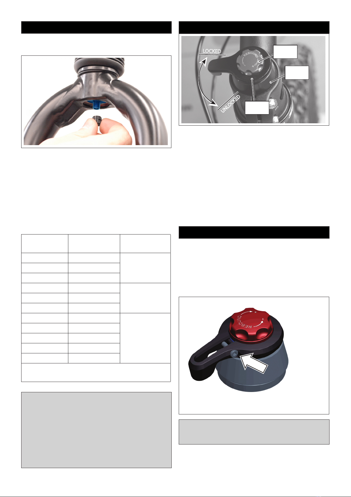
CHECK ADJUSTMENTS - Make sure the adjustment features of your fork
(air pressure, lockout, and rebound) function normally.
PERFORMED BY CANNONDALE DEALER :
RE-GREASE TELESCOPE Every 25 Hours
BEARING RESET Every 25 Hours
BOOT REPLACEMENT As Needed
(Annual recommended)
DISASSEMBLY, INSPECTION, REBUILD -
Inspect and disassembly of telescope and
races, bearings, main telescope parts,
damper cartridge, uids, seals, etc.
NORMAL: Every 100 Hrs
Safety Information
WARNING
NOT FOR JUMPING USE. See “ SECTION B. Intended Use”in your Cannondale
Bicycle Owner’s Manual.
SERVICE BY PROFESSIONAL BIKE MECHANIC ONLY. Special tools are required.
All air pressure must be released before servicing any fork. Never attempt to
work on a pressurized fork.
DO NOT MODIFY THE FORK IN ANY WAY. Do not attempt to alter or modify the
fork in an attempt to install accessories. Please consult with your Cannondale
Dealer.
DO NOT RIDE ON A DAMAGED FORK. STOP RIDING A DAMAGED FORK
IMMEDIATELY. Follow the fork maintenance schedule of this supplement.
Additionally, please ask your Cannondale Dealer to help you develop a complete
maintenance program. Frequent checks are necessary to identify the problems
that can lead to an accident.
Our Factory Tech Room (North America) and Headshok Service Centers (Europe)
provide professional services through Cannondale Dealers for all Headshok sus-
pension forks. Please ask your dealer about the service programs available for
your model fork.
YOU CAN BE YOU SERIOUSLY INJURED, PARALYZED OR KILLED IF YOU
IGNORE THESE WARNINGS.
Cannondale Limited Warranty
Cannondale Headshok (Lefty, Fatty, Solo) suspension products are covered
under the terms and conditions of the Cannondale Limited Warranty. It is
availableonthePoliciespageofourwebsiteat: http://www.cannondale.com
Be sure to read the exclusions listed in the limited warranty. For example,
damage from accidents and improper maintenance are not covered.
Denitions related to forks:
The fork structure is covered in the FRAMES section of the Cannondale
Limited Warranty.
“Fork structure” means certain structural parts of the fork, specically the
fork legs, outer tube, the steerer tube, steerer tube clamps and the inner
tubes with attached dropouts or spindle. The boot, air lter assembly, cable
clamps, needle bearings, races, and bushings which are part of the telescopic
assembly are normal wear and tear items and ARE NOT covered by the limited
lifetime warranty.
The internal fork internal parts are covered by the 1 year (2 years in EU
countries) warranty against defects in materials or workmanship described
in the COMPONENTS section of the Cannondale Limited Warranty. “Internal
fork parts”are dened as items such as damping cartridges and their internal
parts, seals, o-rings, air cylinders, air pistons, springs, elastomers, bumpers,
bushings, needle bearings, races, and oil. Normal wear and tear on these
items is NOT covered by this 1 year (2 in EU) warranty. Like brake pads on a
car, you should expect to have these items professionally replaced or renewed
as you use the fork and they wear.
Fork Warranty Claims
For any warranty claim to be considered, the bicycle/fork must be brought
into an Authorized Cannondale Retailer on the continent on which the
bicycle/fork was purchased. The bicycle/fork must be in assembled condition
and accompanied by the original, dated sales receipt for the bicycle/fork.
Dealer Locator at: http://www.cannondale.com/Dealerlocator
Contact Cannondale
CANNONDALE USA
Cycling Sports Group, Inc.
172 Friendship Road,
Bedford, Pennsylvania, 15522 , USA
(Voice): 1-800-BIKE-USA
(Fax): 814-623-6173
custserv@cyclingsportsgroup.com
CANNONDALE EUROPE
Cycling Sports Group Europe, B.V.
mail: Postbus 5100
visits: Hanzepoort 27
7570 GC, Oldenzaal, Netherlands
(Voice): + 41 61.4879380
(Fax): 31-5415-14240
CANNONDALE AUSTRALIA
Cycling Sports Group Australia Pty Limited
Unit 8, 31-41 Bridge Road
Stanmore, NSW 2048, Australia
(Voice): 61-2-85954444
(Fax): 61-2-85954499
CANNONDALE JAPAN
Namba Sumiso Building 9F,
4-19, Minami Horie 1-chome,
Nishi-ku, Osaka 550-0015, Japan
(Voice): 06-6110-9390
(Fax): 06-6110-9361
cjcustserv@cannondale.com
CANNONDALE UK
Cycling Sports Group
Vantage Way, The Fulcrum,
Poole, Dorset, BH12 4NU
(Voice): +44 (0)1202 732288
(Fax): +44 (0)1202 723366