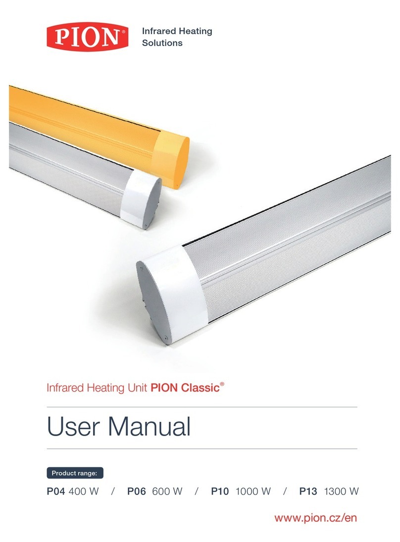
Pion Twiggy TG Series User manual

Infrared Heating
Glass Solutions
®
ThermoGlass®
User Manual
Infrared Heating
Glass Solutions
PION Twiggy TG® – infrared heaters
Model types:
More
heat
Lower
weight
Smaller
dimension
YEARSYEARS
55
W
A
R
R
A
N
T
Y
W
A
R
R
A
N
T
Y
®
ThermoGlass®
TG P04 – 400 W / TG P06 - 600 W / TG P08 - 800 W / TG P10 - 1000 W
Made in
Czech Republic

Heating by means of infra-red radiation is highly eective and reasonably economical. It is currently
considered to be the most eective type of heating. Heat transfer by means of infra-red rays causes that
93% of the radiated heat is absorbed by the oor, walls and objects in the room, which then warm up
the surrounding air.
Install the infrared heaters Twiggy TG® on the ceiling or on the wall. The heating side of the panel
heats up to 180 °C, evenly radiating heat rays and heating up the surrounding surfaces which then use
the accumulated heat to warm up the air.
This heating method has many advantages over the other types, such as increased area for heat transfer,
occurrence of rotating columns of dust limited to a minimum, generally slower cooling of the room,
minimum heating of air under the ceiling or signicantly reduced drying of air. All these features in turn
contribute to the conservation of electricity, thus ranking infra-red heating among the most convenient
and at the same time energy ecient methods of modern heating.
Dear Customer,
Infraline, s.r.o. would like to thank you for the trust you have put in our company by
purchasing the PION Twiggy TG® infra-red heater.
We rmly believe that you will be satised with its thermal comfort, convenience and
low cost of use.
Please take a few minutes to review this manual, which will provide you with
the necessary information about placing and using your new heater.
3

Before using the infrared heater for the rst time, please make sure you have read this user
manual thoroughly; and once nished, keep the brochure handy for possible future consul-
tation, as long as you continue using the unit.
54
TABLE OF CONTENTS
Safety Instructions 5
Technical Data 6
Contents of the Product Package 6
Minimum space and size requirements – Ceiling 6
Minimum space and size requirements – Wall 7
Mounting instructions 7
Manipulation with the pannel 8
Installation 8
Wiring instructions 8
Connection instructions 9
Unit Operation and Maintenance 9
Troubleshooting 9
Storage Instructions 9
Terms of Warranty 10
Certicate of Warranty 11
Delivery Receipt 12
Proof of Sale 12
SAFETY INSTRUCTIONS
When in operation, the heating side of the panel reaches a temperature of 180 °C.
Avoid touching the surface of the heater not only when in the„on“ mode, but also
several minutes after switching o. Risk of burn injury!
•The heater must not be used, if the glass is damaged!
•Mount the IR panel in accordance with the minimum space and size requirements (see page 6, 7).
•Prevent children from operating and touching the heaters!
•This heater is not intended for use by persons whose reduced physical, sensory or mental
capabilities or lack of experience and knowledge prevent them from safe use of the heater
unless supervised or instructed on its use by a person responsible for their safety.
Operational safety
•Do not use the heaters for other than the stated purposes of heating.
•Do not interfere with the structural design of the heaters! Making any structural modications
will void the warranty.
•Install the heaters in accordance with the installation and wiring instructions.
•The heaters are designed to heat residential and utility rooms, except for areas where there is
a risk of explosion.
•The heaters can be used in wet areas, but may not be in direct contact with water.
•Do not sink the heaters in water or other liquids; this would cause damage to the heaters.
•The power cable may not be in contact with the hot surface of the heater!
•Do not hang any other objects on the xed heater and do not cover its surface.
•Heater repairs must be performed by qualied personnel of an authorized service centre.
•Only original spare parts can be used to repair the heaters.
•Do not touch the heating side; this reduces heating eciency.
Wiring instructions
•Connect the heaters to a 230V AC power source only.
•Heater connection to the mains should only be done using a dedicated cable.
•In the case of xed installation with thermostats, entrust the electrical connection to
a professional company.
•Faulty connection of the device will void the warranty!

TECHNICAL DATA
76
Model
TWIGGY
Nominal
Output
(W)
Voltage (V) Rate of
Current
(A)
Dimensions
(mm)
Weight
(kg)
IP Code Heated
area*
(m2)
TG P04 400 230 1,7 930 x 130 x 10 2,5 IP54 6,5
TG P06 600 230 2,6 930 x 190 x 10 3,4 IP54 10,0
TG P08 800 230 3,5 930 x 240 x 10 4,4 IP54 13,0
TG P10 1000 230 4,3 930 x 305 x 10 5,5 IP54 16.5
* indicative only
CONTENT OF THE PRODUCT PACKAGE
•Installation kit
ceiling or wall
•User manual +
Certicate of Warranty
Keep the minimal installation distances (A, B, C, D).
Mounting set designed for ceiling mounting ensures safe installation of the IR panel on
wooden, concrete or metal ceilings. When installing on plasterboard ceilings, it is necessary
to use specic dowels for plasterboard (not included).The thermal resistance of the material
of the ceiling must be at least 80 ° C.
Min. distance
(A) Minimum ceiling mounting distance 100 mm
(B) Distance from the walls 50 mm
(C) Distance from other objects 500 mm
(D) Distance from the oor TG P04 2200 mm
(D) Distance from the oor TG P06 2200 mm
(D) Distance from the oor TG P08 2300 mm
(D) Distance from the oor TG P10 2300 mm
MINIMUM INSTALLATION DISTANCES CEILING MOUNTING
•Twiggy TG® infrared
heating unit
Min. vzdálenost
(A) Minimální montážní vzdálenost 80 mm
(B) Vzdálenost od stěny 50 mm
(C) Vzdálenost od jiných objektů 500 mm
(D) Vzdálenost od podlahy TG P04 1800 mm
(D) Vzdálenost od podlahy TG P06 1800 mm
(D) Vzdálenost od podlahy TG P08 1800 mm
(D) Vzdálenost od podlahy TG P10 1800 mm
MINIMUM INSTALLATION DISTANCES WALL MOUNTING
10,4
13,5
8
16,3
4,6
7
8,3
11,1
TWIGGY 400W
TWIGGY 600W
TWIGGY 800W
TWIGGY 1000W
2,9
9,8
1,5
11,1
3,7
15,8
2,1
17,4
10,4
13,5
8
16,3
4,6
7
8,3
11,1
TWIGGY 400W
TWIGGY 600W
TWIGGY 800W
TWIGGY 1000W
2,9
9,8
1,5
11,1
3,7
15,8
2,1
17,4
10,4
13,5
8
16,3
4,6
7
8,3
11,1
TWIGGY 400W
TWIGGY 600W
TWIGGY 800W
TWIGGY 1000W
2,9
9,8
1,5
11,1
3,7
15,8
2,1
17,4
10,4
13,5
8
16,3
4,6
7
8,3
11,1
TWIGGY 400W
TWIGGY 600W
TWIGGY 800W
TWIGGY 1000W
2,9
9,8
1,5
11,1
3,7
15,8
2,1
17,4
TG P04 TG P06 TG P08 TG P10
Rozměry (mm)
Keep the minimal installation distances (A, B, C, D).
Mounting set designed fo wall mounting ensures safe installation of the IR panel on walls
made of wood, bricks or blocks. When installing on plasterboard walls, it is necessary to use
specic dowels for plasterboard (not included). The thermal resistance of the material of the
wall must be at least 80 ° C.
The lenght of cables of the pannel is 500 mm, it´s necessarry to choose position of the wiring
box in view of this fact.
MOUNTING INSTRUCTIONS
PLASTERBOARD CEILING MOUNTING:
If the plasterboard is wet (i.e. humidity greater than 60%), it is necessary to dry it gradually
during the rst week of heating. If the IR panel is started at full power (i.e. to increase the room
temperature to 22 °C), it would quickly dry the wet plasterboard and this could crack in the
area near the panel.

98
INSTALLATION
•Before the rst run, clean the heating surface with technical alcohol or another
alcohol-based cleaner suitable for glass.
•Select a suitable place to mount the infrared panel on the ceiling or on the wall according
to the chosen mounting kit and mark the position of the holes for anchoring brackets.
•Drill dowel holes with a drill and then place them in the holes .
•Using self-tapping screws, fasten the brackets to the prepared dowels.
•In the case of wall mounting, use the enclosed washers.
•Insert the mounting parts on the back of the panel into the holes in the brackets
and secure the panel with the enclosed nuts.
•Connect the panel to electrical wiring or socket cable.
WIRING INSTRUCTIONS
The electrical wires must be connected to the appliance by a qualied professional in
accordance with the manufacturer‘s instructions in accordance with the applicable local
safety regulations
•The electrical connection of the infrared panel must be provided by a cable with
a corresponding electrical load.
•The electrical connection of the phase L1 and zero N conductors to the infrared pannel
conductors is interchangeable.
•The connection of the infrared panel to the electrical network using a thermostat
must be performed according to the instructions of the thermostat manufacturer.
•Place the thermostat at a height of approx. 1.5 m from the oor. For proper operation,
do not place the thermostat in a zone of direct exposure to heat rays or other heat
sources, or in a draft.
•In accordance with the relevant regulations, the xed wiring must include means
for disconnection from the grid and opening of contacts at all poles.
MANIPULATION WITH THE PANNEL
When handling the heater during installation, use clean cloth gloves. Avoid contact with the
heating glass surface. Both before and after installing the panel, clean it gently (especially
the heating surface) with a perfectly clean and non-abrasive cloth soaked in alcohol-based
window cleaner (to be done only when the panel is switched o and cold!).
9
CONNECTION INSTRUCTIONS
The electrical wires must be connected to the appliance by a qualied professional in accordance
with the manufacturer‘s instructions in accordance with the applicable local safety regulations .
UNIT OPERATION AND MAINTENANCE
The heating unit you have purchased basically does not require any maintenance or
service. There are only two tasks necessary for ensuring its continuous reliable operation
over the years:
•If dusty, clean the panel gently (especially the heating surface) with a perfectly clean
and non-abrasive cloth soaked in alcohol-based window cleaner (to be done only
when the panel is switched o and cold!).
The infrared heater may only be used under the following conditions:
•The ambient temperature must be between -50 °С to +50 °С.
•Relative air humidity at a temperature of 25 °С must not exceed 80%.
The heater should be stored in its original package on such premises where temperature ran-
ges between -50 °С and +50° С and air humidity does not exceed 80%. The heater should be
safeguarded against banging, dust and moisture. The heat-emitting panel should be treated and
handled with extra care; don’t touch its surface, you could damage it! If dusty, clean the panel
gently (especially the heating surface) with a perfectly clean and non-abrasive cloth soaked in
alcohol-based window cleaner.
STORAGE INSTRUCTIONS
TROUBLESHOOTING
Problem Solution Tips
Insucient
heating
performance
• Check what the voltage is on the unit’s terminal clamps, the values should read
230 V +/- 10 V when in operation.
• Make sure that the thermostat is in perfect condition.
• Compare the values indicated on the thermostat with the reading of your
standard indoor thermometer, duly located next to the thermostat. The devia-
tion in thermostat start-up must fall within the range of +/- 2 °C.
The unit does
not heat •Make sure there is power in the power grid.
• Check whether the power cord is intact.
• Check all contacts at the unit’s terminal board.
• Check the power plug contact points .
• See whether the thermostat is working properly.
• Turn to authorized dealers for help.

1110
TERMS OF WARRANTY
•The manufacturer guarantees the heater’s sound operation for a period of 5 years from
the date of purchase.
•Should functional defects occur during the guarantee period as a result of some failure or
shortcoming on the part of the manufacturer, then the manufacturer shall repair such an
appliance free of charge or replace it in compliance with the stipulations of herein stated
terms and conditions.
•The guarantee may be claimed only if an original of the shipping document with a proof
of purchase is presented simultaneously.
•This warranty does not constitute a right for indemnication of damages that originated
as a result of adjustments carried out on the appliance without the prior written consent
of the manufacturer even if these had been made so that the product would comply with
the local technical regulations and safety standards in force.
This warranty is void should any of the following occur:
•The buyer tampers with the construction design of the appliance.
•Incorrect handling and/or operating the appliance.
•Using the appliance in ways that do not comply with the relevant applicable provisions
and/or the stipulations of the user manual provided by the manufacturer.
•Installing equipment whose operation is in breach of technical regulations and safety
standards.
•Repairs carried out by an unauthorised service provider/s or seller/s.
•Some type of accident, a lightning strike, ood, re as well as other adverse causes
that are beyond the reasonable conrol of the manfacturer so that the event is considered
as force majeur.
•Flaws and defects that originated in the course of transportation en route to the client
(apart from times when the transportation is carried out by an authorized dealer or the
manufacturer).
•The internal system within which the appliance was operated turns out to be defective.
•Operating the appliance at a higher voltage than prescribed (i.e. with a deviation of over
10% above the nominal level) and/or at environmental humidity exceeding 80% at 25°C
temperatures.
CERTIFICATE OF WARRANTY
A. The appliance was accepted for repair under warranty:
Name of company:
Address:
Description of reported defect:
Received on (date): Returned on (date):
Signature:
A. The appliance was accepted for repair under warranty:
Name of company:
Address:
Description of reported defect:
Received on (date):
Returned on (date):
Signature:
B. The appliance was accepted for repair under warranty:
Name of company:
Address:
Description of reported defect:
Received on (date):
Returned on (date):
Signature:
Receipt A Receipt B
B. The appliance was accepted for repair under warranty:
Name of company:
Address:
Description of reported defect:
Received on (date): Returned on (date):
Signature:

12 13
Imported on (date):
Company Rep/Importer:
DELIVERY RECEIPT
The PION Twiggy TG® Series
PROOF OF SALE
Name of Merchant:
Merchant’s Address:
Date of Sale:
Salesclerk’s Signature:
TG P04 TG P06 TG P08 TG P10


Declaration of conformity TUV Certicate
Producer: Infraline, s.r.o. – Trojická 437/20 – 120 00 – Prague 2 – Czech Republic
Distributed by:
Other manuals for Twiggy TG Series
1
This manual suits for next models
4
Table of contents
Other Pion Heater manuals
Popular Heater manuals by other brands

Tradesman
Tradesman CP125 User's manual and operating instructions

Inelco
Inelco 1650 operating instructions

Unold
Unold 86315 Instructions for use

Listo
Listo CHS L6n user guide

Induction Innovations
Induction Innovations MINI-DUCTOR VENOM Operating and safety instructions

Goldair
Goldair GPH150 operating instructions