MAD DA2002 User manual

TH225004020-02-2015MAD Disc Aligner
DA2002 en1
DA2002
Instruction Manual
English

TH2250040 20-02-2015 MAD Disc Aligner
en DA20022
Read and follow this instruction manual before
assembling, installing, operating, or servicing
the equipment.
Original instructions
Version: 08
Table of Contents
1. Summary
2. Important Safety Instructions
2.1 First Installation
2.2 Controls DL2002 Lathe
2.3 Controls DU2010 Drive Unit
3. Preparation
4. Fitting Mounting Adapter
4.1 Choice of inserts
4.2 Choice of Z-brackets
4.3 Adapter assembly
4.4 Place and adjust the adapter
5. Fitting the DL2002 Lathe on UMA
5.1 Examples
6. Positioning DU2010 Drive Unit
7. Machining
8. Follow-up
9. Maintenance
10. Trouble shooting
11. Tips / Spare Parts
11.1 Tips
11.2 Spare Parts
12. Electrical Diagram
13. Technical Specification
14. CE-declaration of conformity
15. Disposal instructions
16. Guarantee
3
6
8
12
13
16
18
18
19
20
20
21
22
26
27
28
29
30
31
31
31
32
33
34
34
35
Table of Contents

TH225004020-02-2015MAD Disc Aligner
DA2002 en3
Fig. 1
DL2002
Lathe
DU2010
Drive Unit
Storage Box
1. Summary
Summary

TH2250040 20-02-2015 MAD Disc Aligner
en DA20024Summary
A. 36V cable
B. Silencer band yellow
C. Silencer band red
D. Drive adapter
E. Brush
F. S-hook
G. Cable
H. Safety cover
I. Oil
J. Hex T-spanner
K. Tool for cable working
height
L. Cylinder 12.5x10
M. Cylinder 12.5x20
N. Tool bits
Screws M2.5
O. Conical ring
Fig. 2
A
L
M
K
B
C
D
E
F
G
H
I
J
O
N

TH225004020-02-2015MAD Disc Aligner
DA2002 en5
Fig. 3
Fig. 4
UMA, Fig 3.
Universal Mounting adapter
Short Z-brackets with hole
Ø16.2 mm/ 0.63 inch
UMA accessories, Fig 4.
Long Z-brackets with hole
Ø16.2 mm/ 0.63 inch
Inserts without thread
Ø9 mm / 0.35 inch
Ø10.5 mm/ 0.39 inch
Ø12.5 mm/ 0.47 inch
Inserts with thread
M10 (metric)
Washers
Ø24xØ11x4 / 0.94x0.43x0.16 in
Bolts
M10x25 (metric)
M10x30 (metric)
M10x40 (metric)
Summary

TH2250040 20-02-2015 MAD Disc Aligner
en DA20026Important Safety Instructions
2. Important Safety Instructions
When using this equipment, basic safety precautions should always be followed, includ-
ing the following:
1. Read all instructions.
2. Care must be taken as burns can occur from touching hot parts.
3. Do not operate equipment with a damaged cord or if the equipment has been dropped
or damaged until it has been examined by a qualified service person.
4. Do not let a cord hang over the edge of the table, bench, or counter or come in con-
tact with hot manifolds or moving fan blades.
5. If an extension cord is necessary, a cord with a current rating equal to or more than
that of the equipment should be used. Cords rated for less current than the equipment
may overheat. Care should be taken to arrange the cord so that it will not be tripped
over or pulled.
6. Always unplug equipment from electrical outlet when not in use. Never use the cord to
pull the plug from the outlet. Grasp plug and pull to disconnect.
7. Let equipment cool completely before putting away. Loop cord loosely around equip-
ment when storing.
8. To reduce the risk of fire, do not operate equipment in the vicinity of open containers
of flammable liquids (gasoline).
9. Adequate ventilation should be provided.
10. Keep hair, loose clothing, fingers, and all parts of body away from moving parts.
11. To reduce the risk of electric shock, do not use on wet surfaces or expose to rain.
12. Use only as described in this manual. Use only manufacturer’s recommended attach-
ments.
13. ALWAYS WEAR SAFETY GLASSES. Everyday eyeglasses only have impact re-
sistant lenses, they are not safety glasses.
14. The socket-outlet shall be installed near the equipment and shall be easily accessible.
15. The machine should only be operated by persons authorized to carry out mainte-
nance on the brakes of a vehicle.
16. Do not use the equipment under the influence of drugs or alcohol, or if your judgment
is impaired.
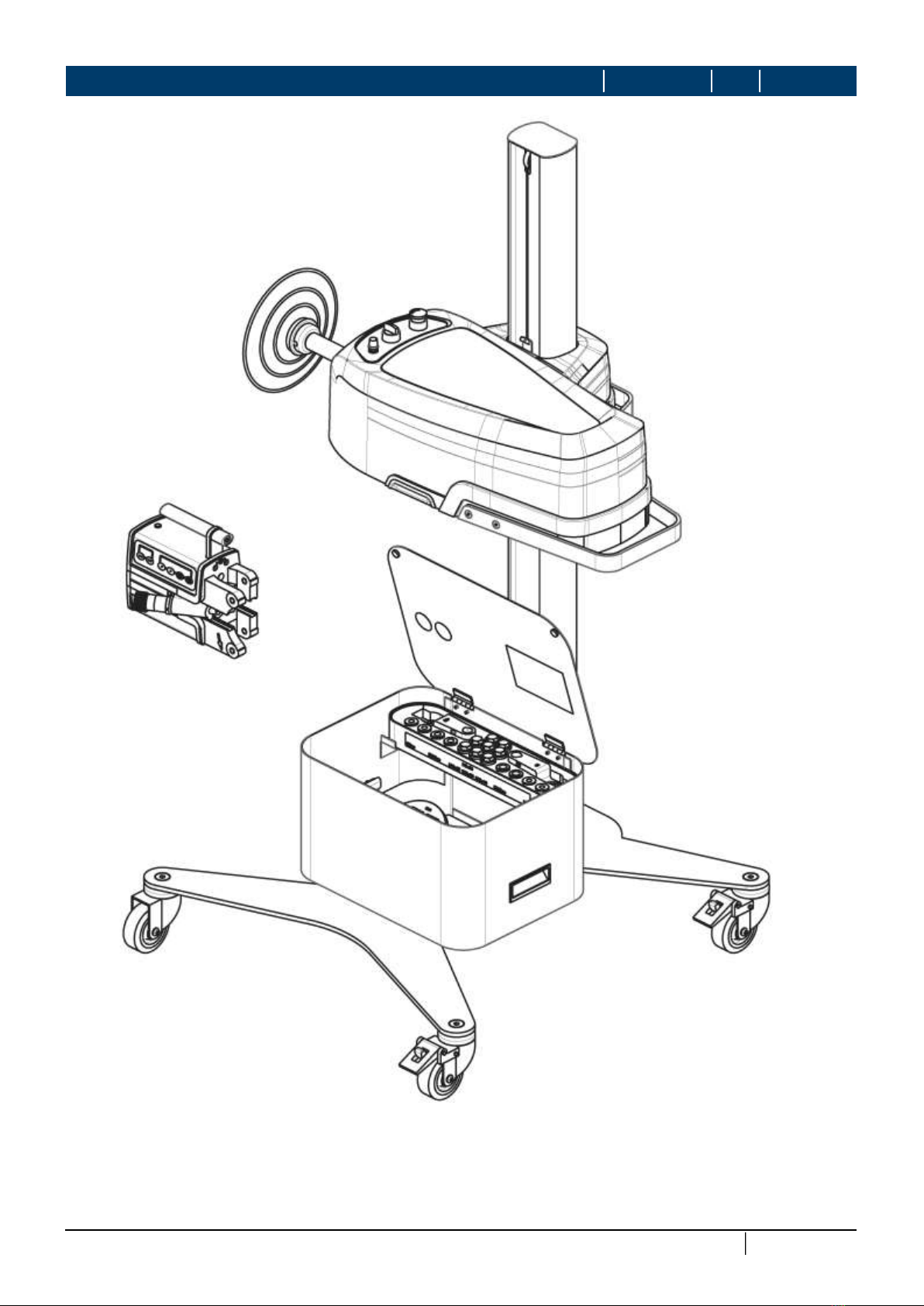
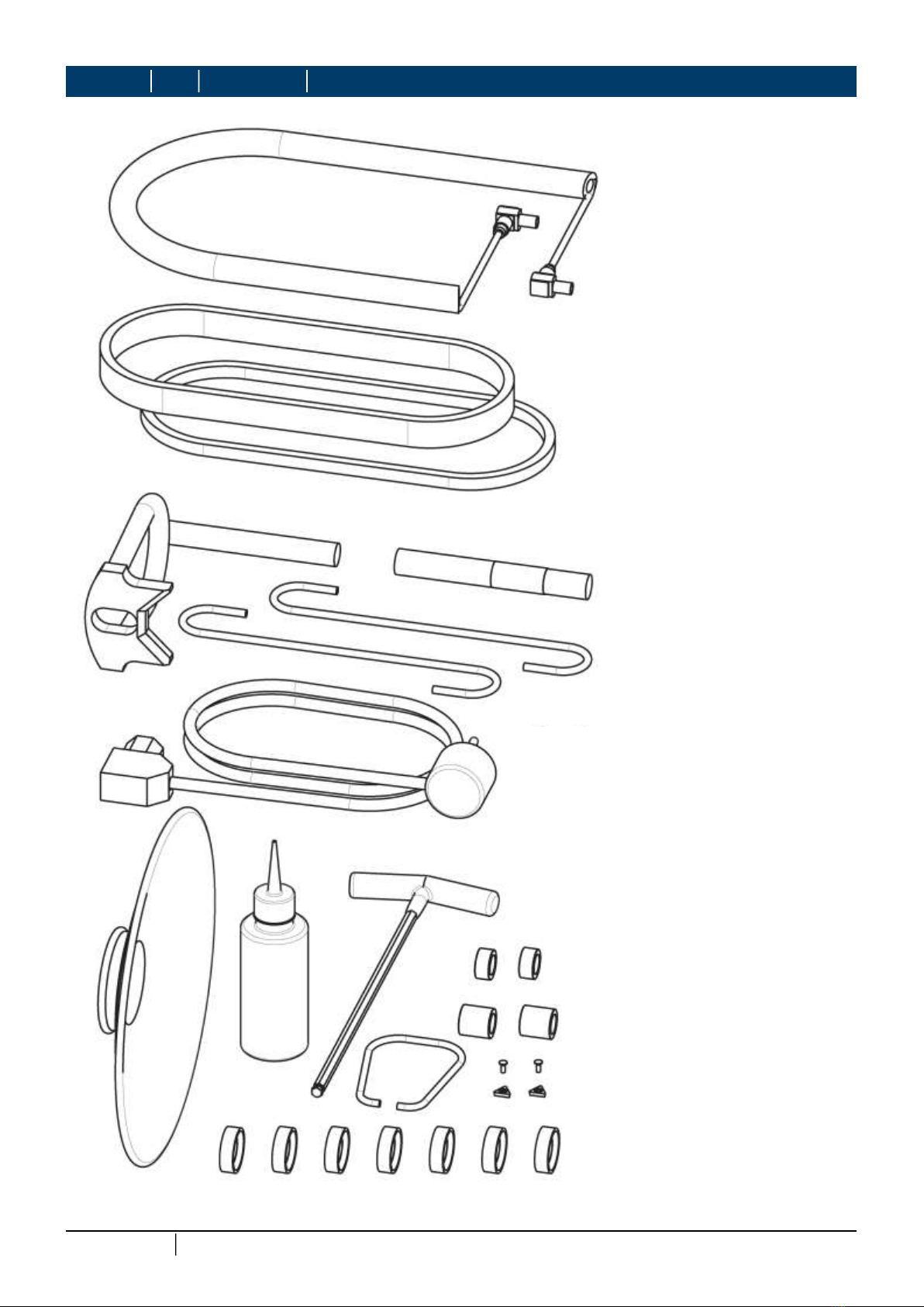
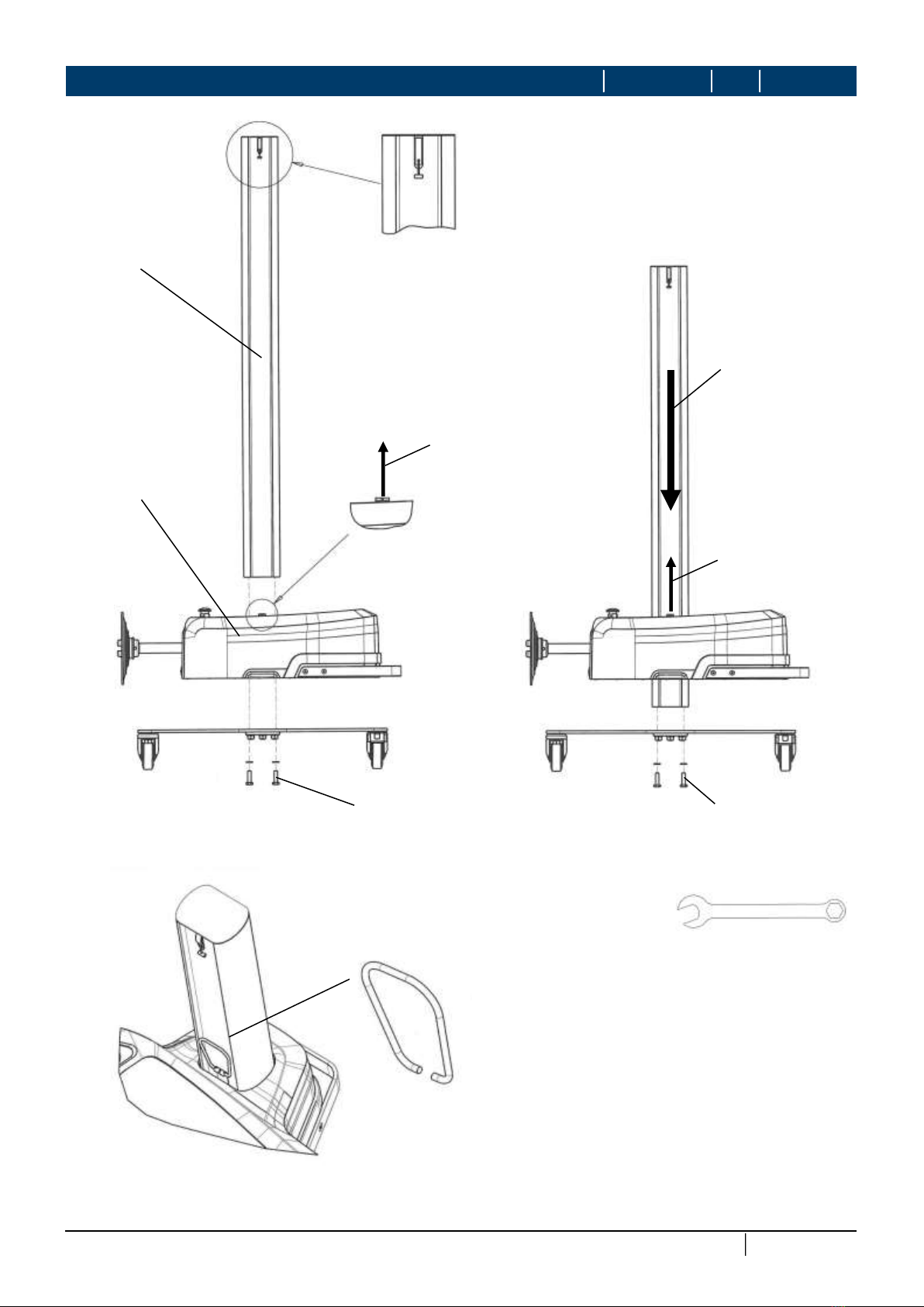
17. Always use the disc lathe DL2002 and the drive unit DU2010 together.
18. Only use the disc lathe DL2002 and the drive unit DU2010 as stipulated in this manu-
al.
19. Do not overload the disc lathe DL2002 and the drive unit DU2010.
20. Follow the electrical specifications as stated on the information plates of both devices.
21. Keep the workplace tidy. A disorderly working environment can lead to accidents.
22. If the equipment is not being used, it should be packed away out of children's’ reach.
23. Children must be kept clear of the equipment at all times.
24. No one else should be allowed to come in contact with the equipment or cables. Keep
them clear of the working area.
25. Do not use the equipment in wet, humid environments, or where there is risk of explo-
sion.
26. Do not use the motor (DU2010) below a level of 46 cm (18 inch) above the ground.
27. Always follow the safety regulations and the (dis-)assembly instructions provided by
the car manufacturer when (dis-)assembling vehicle parts.
28. A 0.5 meter (20 inch) working area is required both next to the drive unit DU2010 and
next to the disc lathe DL2002.

TH225004020-02-2015MAD Disc Aligner
DA2002 en7
Important Safety Instructions
29. The drive unit DU2010 must be equipped with a safety guard (SK-508), as specified in
this manual.
30. Make sure that the surface of the working area is level.
31. Maximum load capacity of top surface is 1 kg (2.2 Lbs).
32. Do not move the equipment while it is running.
33. Warning: machining generates hot chips of metal from the disc.
34. The accompanying risk of fire, injury or burns must be prevented by taking the follow-
ing safety precautions; Wear protective clothing, work gloves, a dust mask. Check
that a fire extinguisher is present.
35. If possible, always use the rubber silencer ring on the outer edge of the brake disc.
This will minimize vibration and/or noise.
36. MAD cannot be held liable for customized attachments or modifications of the equip-
ment.
37. Prior to using the equipment, damaged safety guards or other parts should be
checked in order to ascertain that they still function properly.
38. Check the alignment of the moving parts and their connections, possible part faults,
the set up and indeed any other conditions that might have an influence on the opera-
tion of the equipment.
39. If not otherwise indicated in the manual, damaged safety guards, cables, or other
parts must be replaced or repaired by an recognized technician.
40. Defective electric components must be replaced by a recognized technician.
41. In the interest of effectiveness and safety, keep the tips sharp and the equipment
clean.
42. Hand grips must be kept dry, clean and free from oil and grease.
43. Only maintain the equipment as described in this manual.
44. General repairs, repairs to damaged parts, as well as any other form of maintenance
should only be carried out by a recognized technician (possessing thorough electrical
and mechanical knowledge and experience) using genuine MAD spare parts.
45. Repairs and maintenance may only be carried out on the equipment if it has been
switched off and if the plug has been removed from the mains.
46. Prior to repairs on the drive unit DU2010, carefully short-circuit the connectors of the
capacitor to prevent electric shock injuries.
47. Always use original M.A.D. parts in carrying out repairs or maintenance.
48. Machining the brake discs can affect the brake performance. After machining check if
the deceleration meets the requirements of the law and the car manufacturer.
SAVE THESE SAFETY INSTRUCTIONS
Fig. 5 Fig. 6

TH2250040 20-02-2015 MAD Disc Aligner
en DA20028
Box 1
Fig. 7
Fig. 9
Fig. 8
M12
Tighten 80Nm
M12x30
19mm
8mm
2.1 First Installation
Important Safety Instructions

TH225004020-02-2015MAD Disc Aligner
DA2002 en9
Box 3
Fig. 10
Install alumi-
num tube
through motor
unit and then
bolt to bottom
plate.
4 bolts
M10x35
Tighten 50Nm
Pull
bracket
Pull
bracket
Cable connector
on this side.
17mm
Fig. 12
Fig. 11
Box 2
Box 1
Important Safety Instructions

TH2250040 20-02-2015 MAD Disc Aligner
en DA200210
Attach cable
to clip
Fig. 13
Nut M6
Washer
Washer
Nut M6
Bolt M6x30
Fig. 14
10mm
Important Safety Instructions

TH225004020-02-2015MAD Disc Aligner
DA2002 en11
Using hand grip, push
motor unit down to ap-
proximate height of box.
Fig. 15
Important Safety Instructions

TH2250040 20-02-2015 MAD Disc Aligner
en DA200212
1. Long mounting ear
2. Short mounting ear
3. Slide
4. Direction indicator arrow
5. Cutting depth adjustment knob
6. 36V power plug
7. Handle
8. << and >> Slides high-speed control buttons
9. < and > Slides low-speed control buttons
10. Autofeed 2 - Slides high-speed automatic feed
11. Autofeed 1 - Slides low-speed automatic feed
Fig. 16
1
2
5
4
3
7
6
889910 11
2.2 Controls DL2002 Lathe
Important Safety Instructions

TH225004020-02-2015MAD Disc Aligner
DA2002 en13
Fig. 17 Power inlet 36V outlet
Direction / stop switch
Drive yoke
Safety cover
Emergency stop
Speed adjuster
Fig. 18
Use this hand grip
to reposition height
of drive motor.
Use this hand
grip to roll cart
along shop
floor.
2.3 Controls DU2010 Drive Unit
Important Safety Instructions

TH2250040 20-02-2015 MAD Disc Aligner
en DA200214
Fig. 21 Lock caster wheels during machining.
In case of emergency, power off the drive unit by pressing the emergency stop button.
In a safe situation, the emergency stop is reset by rotating the knurled ring under the
stop button, clockwise. The drive unit is reset by rotating the motor switch to position 0.
Press down for emergency stop. Rotate bottom ring clockwise to reset
emergency stop.
Rotate direction switch to 0 to reset drive
unit.
Important Safety Instructions
Fig. 19 Fig. 20

TH225004020-02-2015MAD Disc Aligner
DA2002 en15
Fig. 22
Speed adjuster Left rotation Right rotation
Emergency stop
Stop / reset
Fig. 23
160 rpm
Normal use, maximum
speed.
130 rpm
Maximum torque, use
on 4WD cars.
160 - 155 rpm
When using a two-post car
lift, gradually adjust motor
speed to reduce vehicle
sway.
80 rpm
Minimum speed. 80 - 120 rpm
Use only autofeed 1 on
the Lathe.
Fig. 27
Fig. 26
Fig. 25Fig. 24
Important Safety Instructions

TH2250040 20-02-2015 MAD Disc Aligner
en DA200216
Fig. 29
Fig. 28
Fig. 32
3. Preparation
Preparation
Fig. 33
Fig. 30 Fig. 31

TH225004020-02-2015MAD Disc Aligner
DA2002 en17
1. Place vehicle on car lift and put transmission in neutral.
2. Raise lift and place vehicle at correct working height, Fig. 28.
3. Check wheel bearing play on both sides of vehicle Fig. 29.
4. If necessary, adjust wheel bearing tolerances as described by the workshop
manual.
5. Immediately after removing the wheel, secure the brake disc to the hub to pre-
vent dirt particles from accumulating between disc and hub.
Use a brake pedal depressor to lock the brake disc.
NOTE: Brake discs are not all mounted to a hub with a screw or nut.
6. Remove the wheel and secure the brake disc with the wheel nuts (or bolts) and
conical rings, Fig. 30.
7. Mount the drive adapter to one of the wheel nuts (or bolts), Fig. 31.
8. The V-shape of the drive adapter must seat firmly along the edge of the hub.
9. Tighten the wheel nuts or bolts evenly to 50 Nm (37 Ft-Lbs).
10. Remove the wheel on the other side of the vehicle and secure that brake disc
with two wheel nuts (or bolts) and conical rings.
11. Remove he brake pedal depressor.
12. Check the thickness of the brake disc, to ensure that the disc will not be below
minimum thickness after machining.
13. Refer to the service manual for the minimum brake disc thickness.
14. If the brake disc is below minimum thickness, it must be replaced. Machining of
a disc below minimum thickness is not permitted.
15. If the brake disc is thicker than the discard size, determine the maximum amount
that could be machined off, for each side of the brake disc.
16. Remove the complete brake caliper and hang it on the S-hook, Fig. 32.
17. Check that the brake line and caliper do not come in contact with the drive shaft
(or any other rotating part).
18. Remove rust and dirt from the mounting surface of the caliper mounting lugs.
The lugs must be clean, as they are the reference point for machining the brake
surface.
19. Fit the rubber silencer band around the outer edge of the brake disc to help re-
duce noise and vibration, Fig. 33.
20. Connect the cable to the Drive Unit and the mains power supply.
21. Connect the 36V cable between Drive Unit and Lathe.
22. Set the motor switch to position 0, then unlock the emergency switch.
23. Move the slides and bit holders of the Lathe in the most rear position. (with ad-
justment knobs cutting depth and << or >> on the control panel. The green LED
of the Lathe should be on.
24. In this position the tool bits cannot be damaged by touching the brake disc.
Preparation

TH2250040 20-02-2015 MAD Disc Aligner
en DA200218
Ø16.2 mm/ 0.63 inch
(without insert)
Ø9.0 mm / 0.35 inch
Ø10.5mm / 0.39 inch
Ø12.5 mm/ 0.47 inch
M10 (metric)
Fig. 34 Fig. 35
Fig. 37
Fig. 36
4. Fitting Mounting Adapter
Fitting Mounting Adapter
4.1 Choose the inserts
Vehicle knuckle:
Without thread Adapter:
Use inserts with thread
Vehicle knuckle:
With thread Adapter:
Use inserts without thread, in the correct size:

TH225004020-02-2015MAD Disc Aligner
DA2002 en19
VehicleLathe
Vehicle Vehicle
Fitting Mounting Adapter
For normal size discs and
knuckles.
Short adapter:
Use z-brackets 39 and 40.
In some cases it
may be neces-
sary
to go between
short and long:
Medium adapt-
er:
Use z-brackets
39 and 42
or: 40 and 41
For large discs and/or deep
placed knuckle mounting
position.
Long adapter:
Use z-brackets 41 and 42.
Fig. 38
Fig. 41
Fig. 40
Fig. 39
VehicleLathe
4.2 Choose the Z-brackets

TH2250040 20-02-2015 MAD Disc Aligner
en DA200220
a
a
Fitting Mounting Adapter
Fig. 42
A.Connecter bow
B.Z-bracket short (39-40) or long (41-42)
C.Inserts with- or without thread
Fig. 44
1. Check the space between lathe and disc:
Keep the space between lathe and disc
short as possible, but at least 5 mm (0.04
inch). Fig 43.
2. Options to correct this dimension;
- Choose long side or short side of the
Lathe
- Use the adapter with longer or shorter z-
bracket(s) Fig 38-41.
3. Do not use air tools when mounting or
removing the mounting adapter and/or
the Lathe.
4. Fit the adapter on the car and adjust the
adapter height
Adapter with M10 metric inserts;
Mount the adapter to the brake caliper
ears, using the M10 bolts supplied,
Fig 34-35.
Adapter with 9, 10.5, 12.5 mm or no in-
serts;
Using the original caliper bolts, mount the
adapter to the threaded caliper ears,
Fig. 36-37.
a. Face the bow toward the axle.
b. Ensure the correct-length bolts are
used. When the bolts are fully inserted,
they must not touch the brake disc.
c. If necessary, use the spacer tubes pro-
vided to achieve the correct bolt length.
d. Ensure the slide piece hex head bolts
are loose.
5. Position the slide piece in the center of
the hub. Then hand tighten the UMA
mounting adapter M10 bolts, Fig. 44.
Fig. 43
4.3 Assemble the adapter
4.4 Fit and adjust the adapter
AB
C
Table of contents
Other MAD Automobile Accessories manuals
Popular Automobile Accessories manuals by other brands

Husky
Husky 31853 Assembly, Installation, Operation and Maintenance Instructions

Ridewell Suspensions
Ridewell Suspensions RAR-240 owner's manual

Rago FABRICATION
Rago FABRICATION R2200TTUNBCM installation guide

Sena
Sena 50S user guide

Blackweb
Blackweb BWA18AV003 instruction manual

Brodit
Brodit ProClip 854399 installation instructions