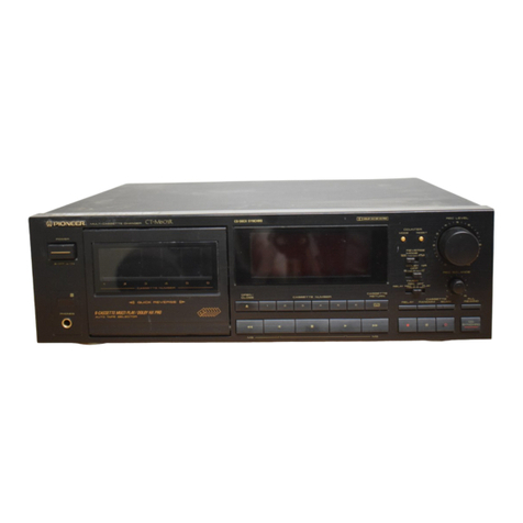
Pioneer CT-5 User manual
Other Pioneer Cassette Player manuals
Pioneer
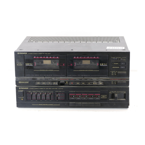
Pioneer DC-X77Z User manual
Pioneer
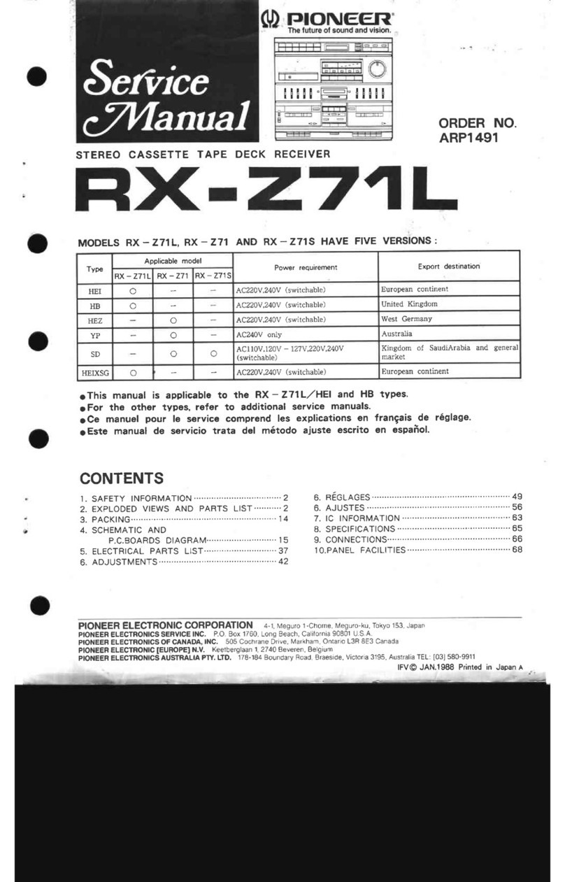
Pioneer RX-Z71: User manual
Pioneer
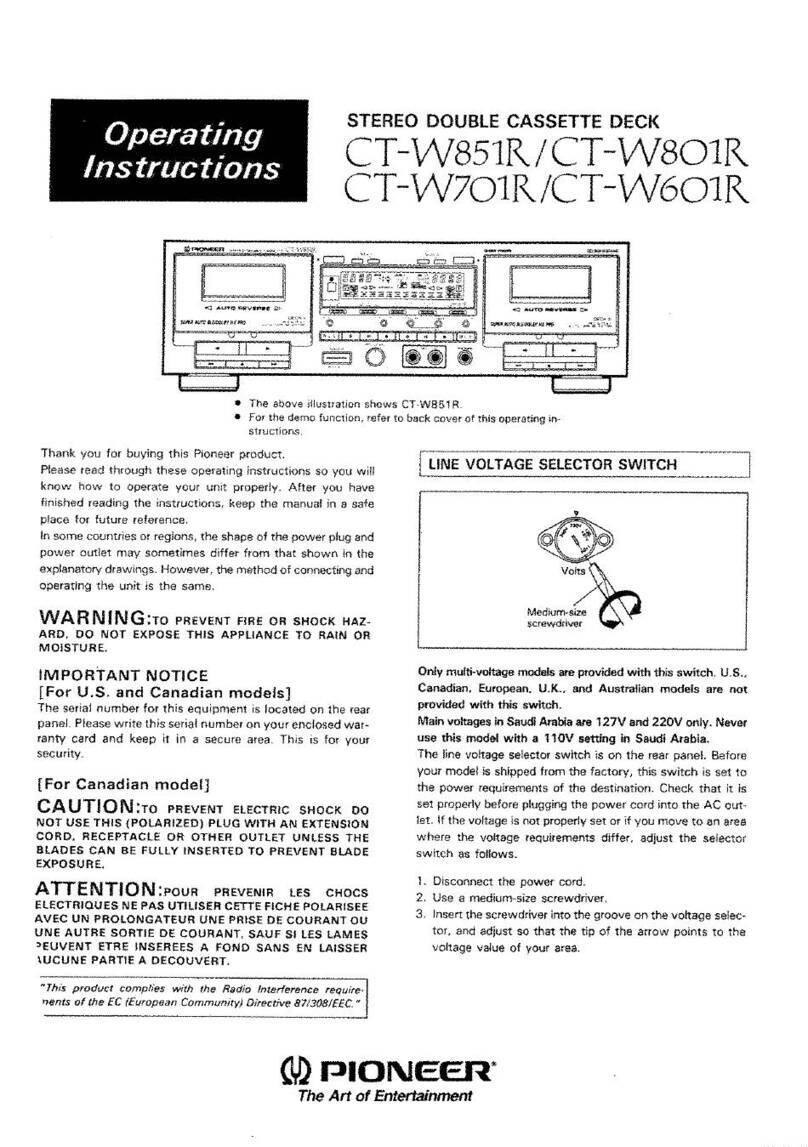
Pioneer CT-W851R User manual
Pioneer
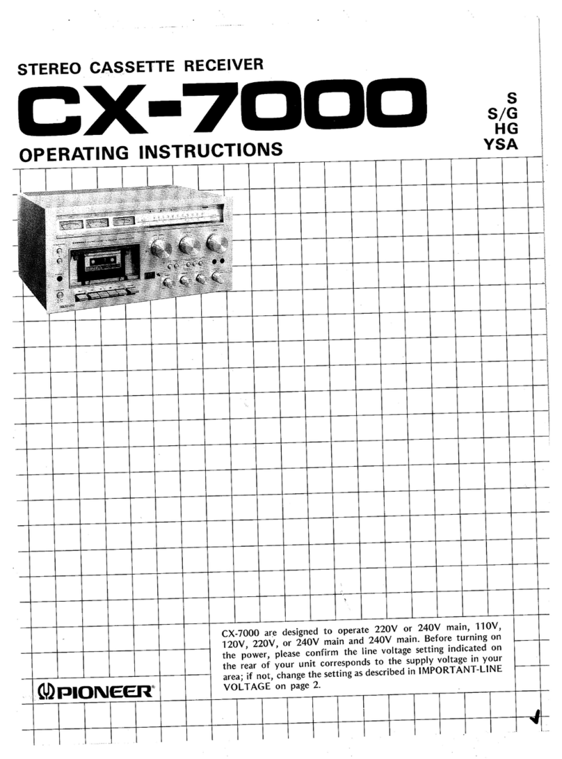
Pioneer CX-7000 User manual
Pioneer
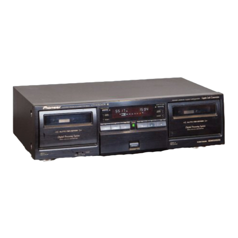
Pioneer CT-W806DR User manual
Pioneer
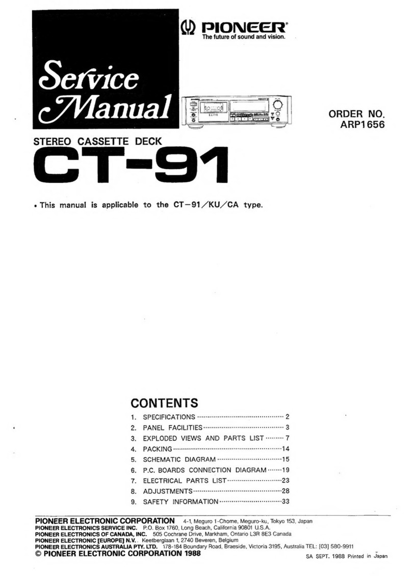
Pioneer CT-91 User manual
Pioneer
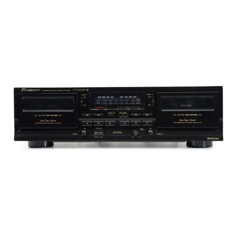
Pioneer CT-W208R - Dual Cassette Deck User manual
Pioneer
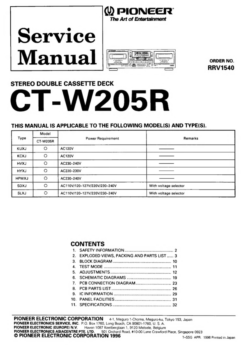
Pioneer CT-W205R User manual
Pioneer
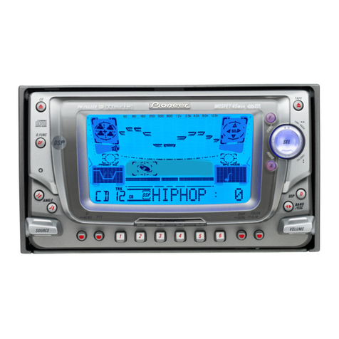
Pioneer FH-P6600R User manual
Pioneer
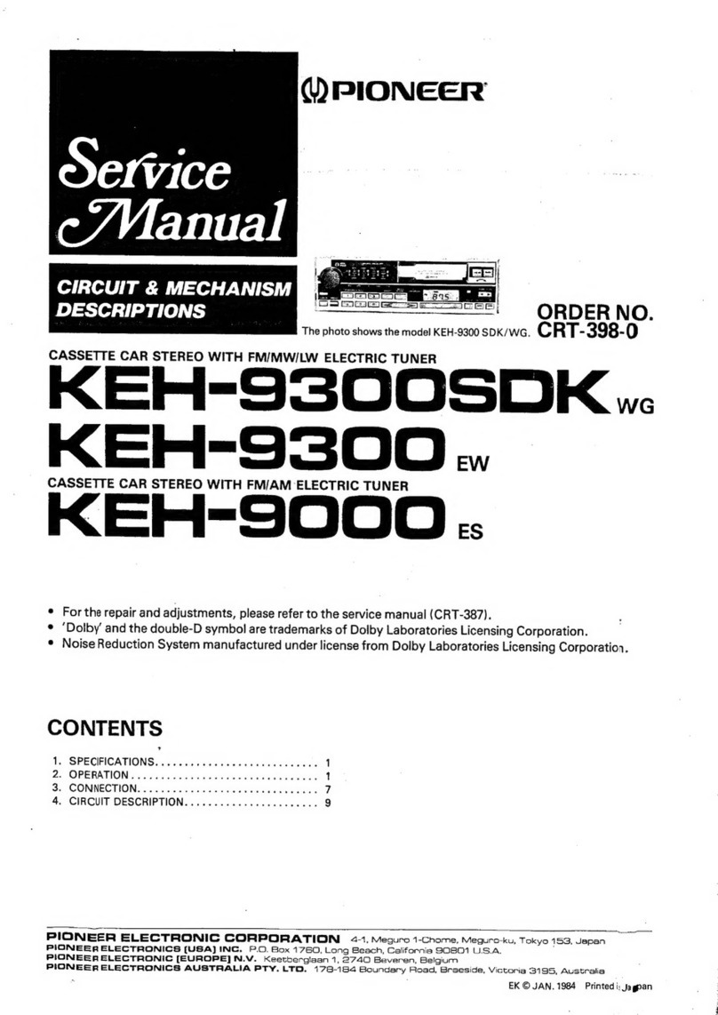
Pioneer KEH-9300SDK WG User manual
Pioneer
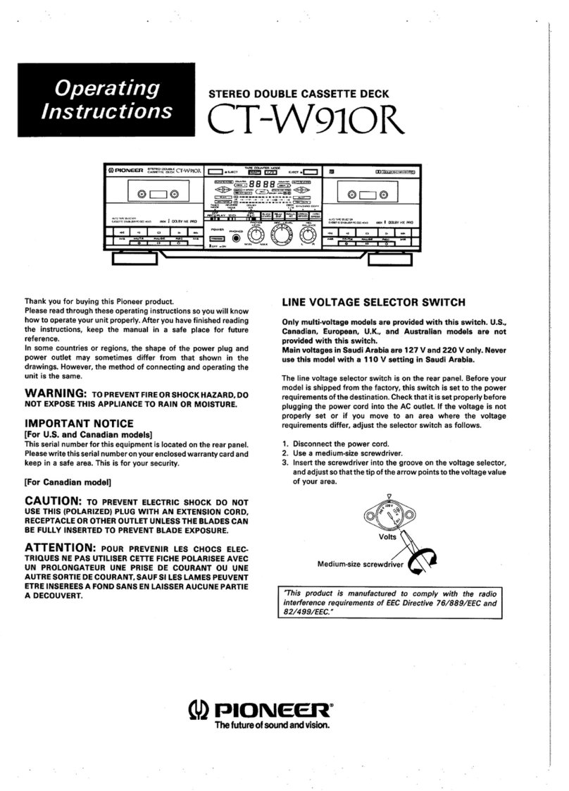
Pioneer CT-W910R User manual
Pioneer
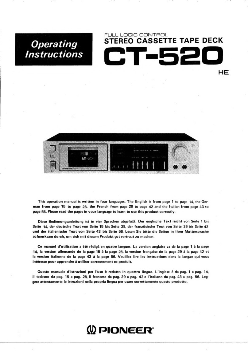
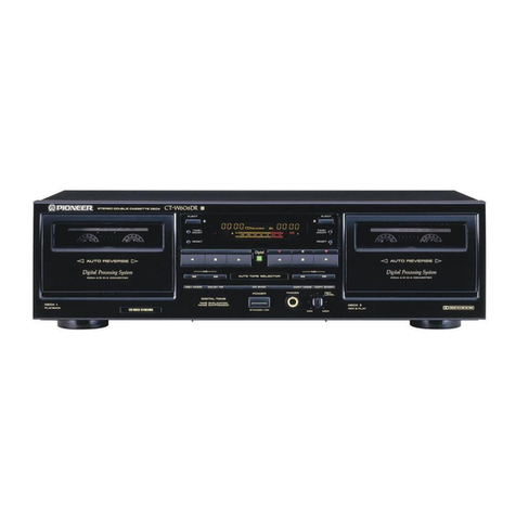
Pioneer CT-520 User manual
Pioneer
Pioneer CT-W606DR - Dual Cassette Deck User manual
Pioneer
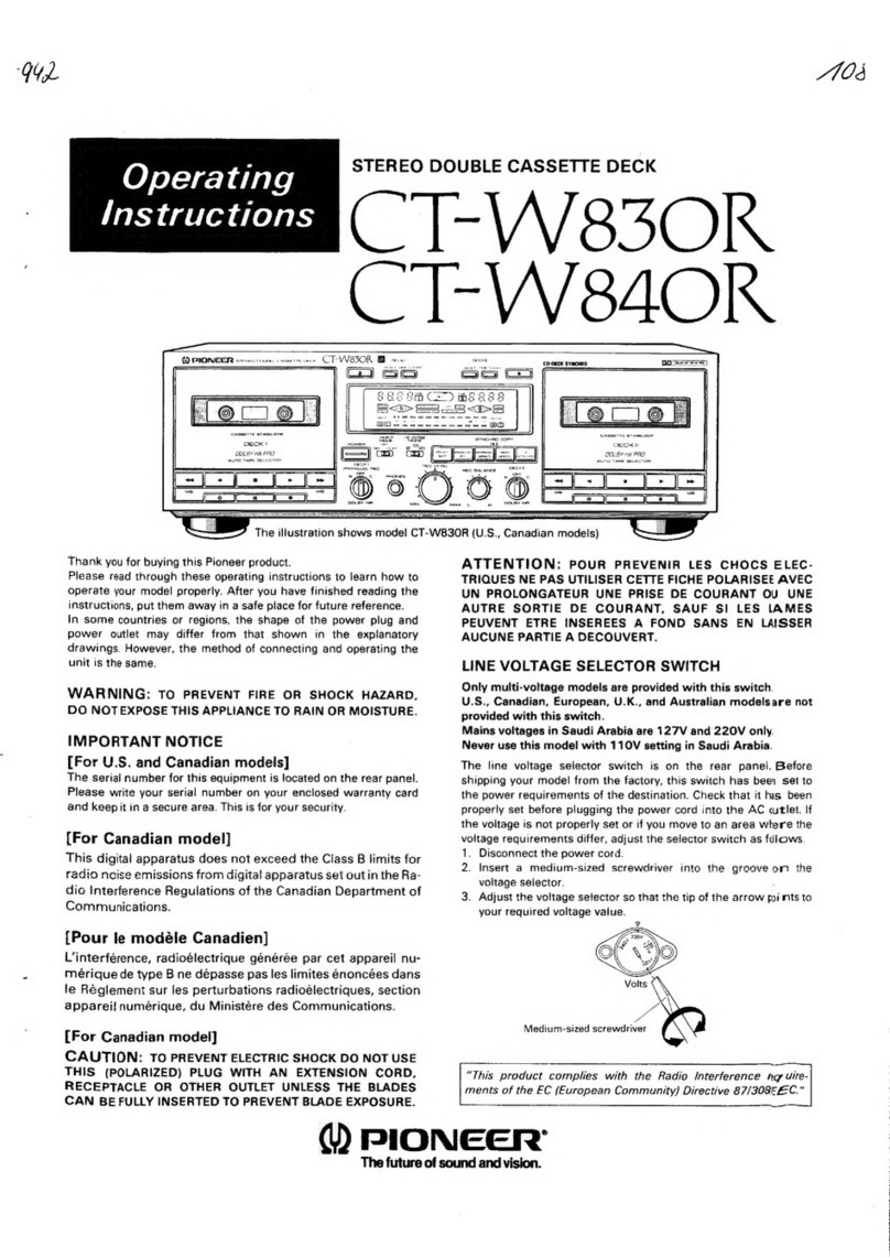
Pioneer CT-W830R User manual

Pioneer
Pioneer CT-730 User manual

Pioneer
Pioneer CT-W208R - Dual Cassette Deck User manual

Pioneer
Pioneer KEH-P6025 User manual
Pioneer
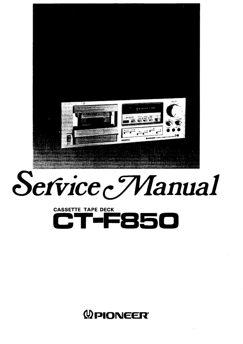
Pioneer CT-F850 User manual
Pioneer
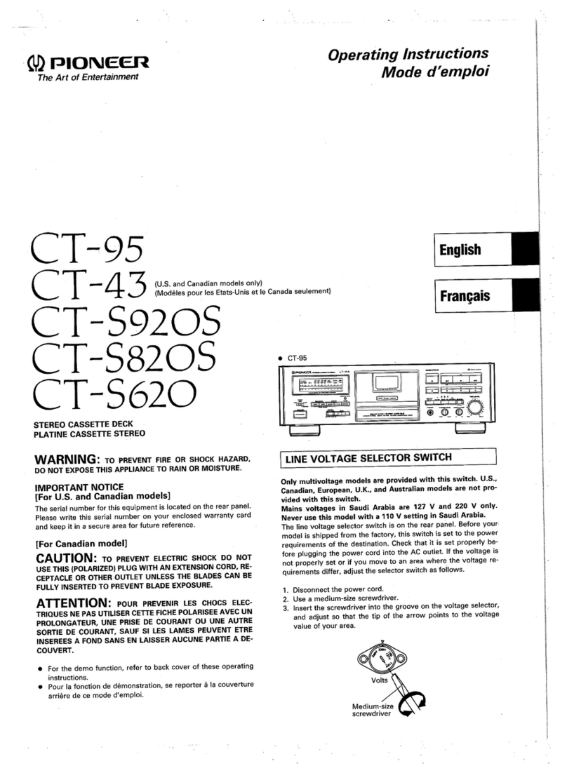
Pioneer CT-95 User manual

Pioneer
Pioneer XR-A100 User manual
