manuals.online logo
Brands
  1. Home
  2. •
  3. Brands
  4. •
  5. Pioneer
  6. •
  7. Cassette Player
  8. •
  9. Pioneer CT-91 User manual

Pioneer CT-91 User manual

Q)
PIONEER’
The
future
of
sound
and
vision.
Service
SALES
IED|
STEREO
CASSETTE
DECK
e
This
manual
is
applicable
to
the
CT—91/KU/CA
type.
ORDER
NO.
ARP1656
CONTENTS
if
SPECIFICATIONS
we
W
event
neem
eccer
use
ceecorceesaeeasasssnevies
2
2.
PANEL
FACILITIES
Cree
rececececccccesseneesccccsecceeseces
3
3,
EXPLODED
VIEWS
AND
PARTS
LIST
«+--+
7
4,
PACKING
4)
(0.6
0
6'0°6:6
[00
e'0's/e
wb.0'e
win.le
06:0
6.0
a'e'ein'e
eeialsiesieee
eselciesicsioee
14
5.
SCHEMATIC
DIAGRAM
Seer
cneseececcetoverecseravceeas
15
6.
P.C.
BOARDS
CONNECTION
DIAGRAM
-----19
7,
ELECTRICAL
PARTS
LIST
ev
eceencecccerseserenncsece
23
8.
ADJUSTMENTS
PYEPPeSTETTeTePee
reece
eer
re
errr
reer
r
eerie
28
9,
SAFETY
INFORMATION
De
ceererecesescencereececesenes
33
PIONEER
ELECTRONIC
CORPORATION
=
4-1,
Meguro
1-Chome,
Meguro-ku,
Tokyo
153,
Japan
PIONEER
ELECTRONICS
SERVICE
INC.
P.O.
Box
1760,
Long
Beach,
California
90801
U.S.A.
PIONEER
ELECTRONICS
OF
CANADA,
INC.
505
Cochrane
Drive,
Markham,
Ontario
L3R
8E3
Canada
PIONEER
ELECTRONIC
[EUROPE]
N.V..
Keetberglaan
1,
2740
Beveren,
Belgium
PIONEER
ELECTRONICS
AUSTRALIA
PTY.
LTD.
178-184
Boundary
Road,
Braeside,
Victoria
3195,
Australia
TEL:
[03]
580-9911
©
PIONEER
ELECTRONIC
CORPORATION
1988
dig
cen?
ance
waa
We
can
1.
SPECIFICATIONS
SYSIEMSS:
sheen
intios
oe
eRe
4
track,
2-channel
stereo
Heads...........
Laser
amorphous
playback
head/
Hard
parmalloy
recording
head
combination
x
1
Erasing
head:(Ferrite
head)
x
1
MOlOIS
cars
acs
bene
iad
sede’
DC
servo
capstan
motor
x
1
DC
reel
motor
x
1
DC
auxiliary
motor
x
1
Wow
&
Flutter...
00.00.00
ee
0.022%(WRMS)
+
0.052%
(DIN)
Fast
winding
time............
Approximately
80
seconds
(C-60
tape)
Frequency
response
(—
20
dB
recording)
Metal
tape...
6...
eee,
20
Hz
to
23,000
Hz
Chrome
tape
.................0..
20
Hz
to
21,000
Hz
Normal
tape....................
20
Hz
to
21,000
Hz
Signal-to-noise
ratio
.
DOLBY
NR
OFF..................
More
than
60
dB
Noise
Reduction
Effect
DOLBY
NR
B
type
ON
....
More
than
10
dB
(at
5
kHz)
DOLBY
NR
C
type
ON
....
More
than
19
dB
(at
5
kHz)
Harmonic
distortion
..........
No
more
than
0.6%
(0
dB)
IV
OUG
oee
ce
te
Cutt
Sets
eee
Woe!
tanane
Ge
Sat
atl
Sete
LINE:
67
mV
(Input
impedance:
50
kQ)
OUIDUEs
ew
noes
Nae
ee
ee
out
LINE:
316
mV
(Output
impedance:
1.4
kQ)
Headphones:
0.8
mw
(Load
impedance
82
VR
Max.)
Subfunctions
*
3-mode
counter
(4-digit
electronic
counter)
e
Auto
Tape
Loose
Canceller
function
¢
Meter
range
selection
(WIDE/EXPAND)
e
Auto
Monitor
function
(TAPE/SOURCE
auto
selection)
e
Auto
Meter
Warning
zone
Selector
¢
Power
Eject
(OPEN/CLOSE)
¢
Music
Search
(over
+15
selections)
e
Tape
Return/Return
play
*
Headphones
jack
(with
volume
control)
e
Bias
control
°
MPxX
filter
e
Auto
Space
Recording
Mute
e
Auto
Tape
Selector
e
Playback/Recording
timer
start
function
*
Dolby
Noise
Reduction
(B
Type/C
Type)
e
Dolby
HX
Pro
system
¢
FL
Level
Meter
Peak-hold
function
(15
+
1
segments)
e
System
remote
control
available
Miscellaneous
Power
Requirements
U.S.,
Canadian
models
........
....,
AC
120V,
60
Hz
Power
Consumption
U.S.,
Canadian
models...
00.00.00.
ee,
25W
Dimensions
...........
457(W)
x
133.5(H)
x
372(D)
mm
18(W)
x
5-1/4(H)
x
14-5/8(D)
in
Weight
(without
package)...........
10.8
kg
(23
Ib
13
02)
Accessories
Operating
instructions...
2.2.00...
ee.
1
GOMMECIING
COPS
sce
ice
cay
te
seat
aid
das
2
Senne
ae
pees
2
Control
Cord
yn
ox
aid
svanle
sign
bod
dete
OST
e
es
alas
1
NOTE:
Specifications
and
design
subject
to
possible
modifications
without
notice,
due
to
improvements.
2.
PANEL
FACILITIES
Onin
STEREO
CASSETTE
Deck
UT")
s
POWER,
@
POWER
switch
Turn
the
power
on.
After
the
power
is
turned
on,
the
dotted
lines
in
the
level
meter
flash
for
approximately
4
seconds
until
the
circuits
of
the
unit
have
stabilized.
The
unit
will
not
operate
during
this
time
even
if
one
of
the
operation
buttons
is
pressed.
@
Cassette
door
OPEN/CLOSE
button
NOTE:
If
the
cassette
door
is
closed
while
the
unit
is
turned
OFF,
and
the
power
is
then
turned
ON,
the
cassette
door
may
open
and
close
after
pressing
one
of
the
operation
buttons.
This
occurs
when
the
microprocessor
resets
the
door
mechanism
to
its
initial
state
and
does
not
indicate
any
malfunctioning
of
the
unit.
©
COUNTER
selectors
RESET:
Resets
the
counter
indication
to
''0000"'
MODE:
Each
time
this
button
is
pressed,
one
of
the
following
three
modes
is
set
in
sequence.
e
Normal
tape
counter
e
Time
counter
(displays
the
elapsed
playback
or
recording
time)
e
Remaining
time
counter
{displays
the
remaining
time
of
the
tape)
@
TAPE
CAPACITY
selector
To
indicate
the
correct
time
value
in
the
remaining
time
counter
mode,
this
selector
must
be
set
in
accordance
with
the
tape
used.
eens
C90
~
C80L
>
C60
>
C46L
3]
@
TAPE
RETURN
button
This
button
is
used
in
the
tape
counter
mode
to
fast
forward
or
rewind
the
tape
to
a
point
near
the
counter
reading
'‘0000".
@
DOLBY
NR
selectors
ON/OFF:
Used
to
turn
the
Dolby
NR
system
circuits
ON
or
OFF.
B/C:
With
the
ON/OFF
switch
in
the
ON
position,
Dolby
NR
B
or
C
can
be
selected
with
this
switch.
@
MPxX
FILTER
switch
This
switch
is
effective
only
during
recording
with
Dolby
NR.
©
REC
LEVEL
control
©
REC
BALANCE
control
@
TIMER
mode
selector
REC:
Set
to
this
position
for
timer
recording.
PLAY:
Set
to
this
position
for
timer
playback.
OFF:
When
the
timer
is
not
to
be
used,
set
the
selector
to
this
position.
(Normally
leave
the
selector
in
this
position.)
@
PHONES
LEVEL
control
@
PHONES
jack
@®
Cassette
door
@
Rewind
(<<)
button
Press
this
button
to
rewind
the
tape.
When
the
button
is
pressed
during
playback,
the
tape
rewinds
to
the
beginning
of
the
current
selection,
and
playback
starts.
If
the
button
is
pressed
twice,
the
tape
rewinds
to
the
selection
before
the
current
selection.
@®
Stop
(
Mf)
button
@
Play
(>)
button
@
Fast
forward
(>>)
button
Press
this
button
to
fast
forward
the
tape.
When
the
button
ts
pressed
during
playback,
the
tape
advances
to
the
beginning
of
the
next
selection,
and
playback
starts.
If
the
button
is
pressed
twice,
the
tape
advances
to
the
selection
after
the
next
selection.
@
Recording
(
@
)
button
When
this
button
is
pressed,
the
unit
is
set
to
one-touch
recording
pause
(recording
standby
mode).
Press
the
PAUSE
button
to
start
recording.
@
Pause
(
m
)
button
The
tape
transport
can
be
momentarily
stopped
by
pressing
this
button
during
recording
or
playback.
Press
the
button
again
to
restart
operation.
The
button
does
not
operate
during
fast
forward
or
rewind.
@
Record
muting
(
©
)
button
Press
this
button
to
create
an
unrecorded
space
during
recording.
@
METER
RANGE
selector
Selects
WIDE
or
EXPAND
as
scale
range
for
the
level
meter.
@
MONITOR
selector
For
monitoring
the
sound
during
recording,
this
switch
can
be
used
to
switch
between
source
sound
and
just
recorded
sound.
@®
Rec
BIAS
control
It
is
possible
to
adjust
the
bias
according
to
the
tape
used
and
the
source
to
be
recorded.
OPERATING
DISf
—
@)
Counter
«
The
counter
has
e
When
the
cassett
is
displayed.
¢
During
music
sear
(2)
TAPE
RETURN
Lights
up
during
tac
8)
Tape
transport
44
Lights
up
wt
&
=
Lights
up
du
pause
andr
Pr
©
Lights
up
wi
ge:
Lights
up
in
(4)
MUTE
Flashes
and
lights
d
(S)
REC
Lights
up
during
rec
6)
Warning
zone
Changes
according
t
meter
range.
®
Monitor
source
TAPE:
Recorded
SOURCE:
Original
sc
Scale
for
WIDE
ding,
this
switch
can
be
nd
just
recorded
sound.
1g
to
the
tape
used
and
OPERATING
DISPLAY
I
=
=
68.
-35
-28
PEAK
HOLD
ri
f=
Pn
ae
eae
ae
[_TAPE'RETURN
|]
<<
D>
PP
HI
[rec]
CO
in
init
mitt
nit
nt
ttt
nin
tit
vn
vin
{
MUTE
|
@)
Counter
e
The
counter
has
three
display
modes.
e
When
the
cassette
door
is
opened,
the
message
‘‘OPEN"
is
displayed.
e
During
music
search
the
number
of
selections
is
displayed.
(2)
TAPE
RETURN
Lights
up
during
tape
return
operation.
3)
Tape
transport
modes
“4
=
Lights
up
when
rewinding
the
tape.
®
~.
Lights
up
during
playback,
playback
pause,
recording
pause
and
recording.
Flashes
during
music
search.
»P
—
Lights
up
when
fast
forwarding
the
tape.
wa
=:
Lights
up
in
the
pause
mode.
(4)
MUTE
Flashes
and
lights
during
recording
mute
operation.
(&)
REC
Lights
up
during
recording.
6)
Warning
zone
Changes
according
to
the
type
of
tape
used
and
to
the
selected
meter
range.
®
Monitor
source
TAPE:
Recorded
sound
SOURCE:Original
source
sound
Scale
for
WIDE
range
9)
Level
L:
Left
channel
R:
Right
channel
The
QO
mark
indicates
the
reference
level
for
the
Dolby
NR
system,
REMAIN
Lights
up
when
the
remaining
time
counter
mode
is
selected.
(1)
LARGE
HUB
Lights
up
when
the
TAPE
CAPACITY
selector
is
pressed
in
the
remaining
time
counter
mode,
and
the
Large
Hub
mode
is
set.
(12)
TIME
COUNTER
Lights
up
in
the
time
counter
mode.
(3)
DOLBY
NR
B/C
Indicates
the
selected
Dolby
Noise
Reduction
system,
B
or
C.
0
dB
position
for
EXPAND
range
(15)
MPX
FILTER
Lights
up
when
the
MPX
FILTER
switch
is
pressed
while
the
Dolby
NR
system
is
ON.
0
dB
position
for
WIDE
range
G2)
Tape
type
The
unit
will
automatically
detect
and
display
the
tape
type
(NORMAL/CrO2/METAL)
of
the
cassette
inserted.
When
no
tape
is
inserted,
METAL
is
displayed.
Scale
for
EXPAND
range
@
Connections
Connection
of
input
and
output
cords
e
The
cords
to
be
used
have
white
and
red
pin
plugs.
e
Connect
white
plugs
to
the
left
channel
(L),
and
red
plugs
to
the
right
channel
(R),
making
sure
that
the
colors
match.
Take
particular
care
to
insert
the
plugs
all
the
way
in.
--
(Not
provided
in
the
European
model.)
—s
CONTROL
IN
jack
Connect
this
jack
to
the
CONTROL
OUT
jack
of
a
component
equipped
with
the
Pioneer
System
Remote
Control
(bearing
White
plug
the
RI
mark)
using
the
supplied
mini-plug
cord,
and
you
ON
will
be
able
to
operate
the
component
using
the
system
ae;
Right
channel
remote
control.
Red
plug
CONTROL
OUT
jack
Intermediary
output
of
remote
control
signals
from
the
above
input
jack.
Connect
it
to
the
CONTROL
IN
jack
of
another
component
compatible
with
the
Pioneer
System
Remote
Control.
Left
channel
Connection
to
an
audio
timer
For
details
on
the
connection
to
an
audio
timer,
refer
to
the
instruction
manual
of
the
audio
timer.
CT-91
Recording
connection
Playback
connection
Supplied
When
performing
unattended
cords
p
g
recording
or
wake-up
playback
Audio
timer
www
wewe
Mustration
not
applicable
to
U.K.
model.
Household
AC
outlet
were
eee
eee,
ete
wwons,
i
Stereo
amplifier
CT-91
3.
EXPLODED
VIEWS
AND
PARTS
LIST
NOTES
:
¢
Parts
without
part
number
cannot
be
supplied,
¢
The
A
mark
found
on
some
component
parts
indicates
the
impotance
of
the
safety
factor
of
the
part,
Therefore,
when
replacing,
be
sure
to
use
parts
of
identical
designation.
*
Parts
marked
by
“©”
are
not
always
kept
in
stock,
Their
delivery
time
may
be
longer
than
usual
or
they
may
be
unavailable,
3.1
EXTERIOR
Parts
List
of
Exterior
Mark
No.
Part
No,
>
&
PPP
OON®D
oO
&k
WAN=
CM-22C
PDG1015
REK-074
REK-—080
RTT1060
SLF-401C
DBK~
106
PNB1109
RBF1019
RBH1150
RBL—059
RBM-014
REB—223
REB1038
REB1057
REC1008
RNH
~
184
AAM1001
ABA1023
AMR1159
PAC1208
RAC—668
RAC1203
RAC1204
RAC1205
RAC1206
RAC1262
RAH1369
RAP1003
RMS1007
RMS1008
RNK1284
RNK1285
RNK1411
RNK1412
RXA1
158
RXA1160
RAH1197
RAH1198
RAH1368
RAH1371
RXX1064
RXX1128
RXX1129
RXX1130
____Description
Strain
relief
AC
power
cord
Fuse
(FUI03
1.6A//125V)
Fuse
(FU101,FU102
1A/125V)
Power
transformer
(T1)
Diode
(D11)
Mounting
plate
Absorber
B
Washer
Spring
Cassette
plate
spring
Nylon
rivet
(3.55.5)
Cover
cushion
(D)
Stabilizer
B
Rubber
spacer
(A)
Wood
spacer
Cord
clamper
Name
plate
Screw
Leg
assembly
Knob
(PHONES
LEVEL,
BIAS)
Knob
A
(TIMER)
Button
(POWER)
Button
(DOLBY,
MPX)
Button
(COUNTER)
Button
(CONTROL)
VR
knob
BCREC
BALANCE)
FL
filter
Under
escutcheon
Side
wood
(L)
Side
wood
(R)
Door
Button
holder
Side
mold
(L)
Side
mold
(R)
VR
knob
assembly
(A)
Button
assembly
(MONITOR)
Door
fens
FL
panel
Side
panel
Door
panel
Cassette
plate
assembly
Bonnet
Door
assembly
Front
panel
assembly
Mark
Exterior
A
Part
No.
Description
BBZ40PO80FCC
Screw
BBZ30PO60FCC
Screw
IBZ30PO80FCC
Screw
BBT30PO80FZK
Screw
BBZ40P160FCC
Screw
PYC30P100FMC
Screw
BBZ26PO80FZK
Screw
PMA30PO60FCU
Screw
BIAS
VR
unit
Headphone
unit
INPUT
VR
unit
Amp
unit
FL
unit
Switch
unit
OSC.HX
unit
Timer
unit
Control
unit
Power
supply
unit
Tape
mechanism
unit
Power
transformer
sheet
Tape
mechanism
sheet
VR
rod
Center
stay
VR
_
holder
Panel
stay
PS
holder
P.C.B
holder
Shield
plate
VR
rod
guide
Joint
P.C.B
stud
Cassette
plate
Front
panel
Ne
ee
Rear
panel
Motor
favel
Cay
he
a
x
4
La
Vf
Ny
‘
nee
YASS
AA)
D
3.2
Parts
Mark
List
of
Mechanism
Unit
No.
Part
No.
Description
Mark
1
RSF-031
Micro
switch
2
RSX-059
Rotary
encoder
3
RXM1016
Capstan
motor
assembly
4
RXM1018
Reel
motor
assembly
5
RBA-064
Step
screw
6
RBL-044
Thrust
spring
7
REB-—408
Rubber
cushion
8
RBL-028
Pinch
spring
9
RBL—030
Pinch
thrust
spring
10
RBL-098
Pinch
spring
(SUB)
11
REB1073
Capstan
belt
12
REB1074
Capstan
belt
(A)
13
RNL—-016
Tape
guide
14
RXA1235
Flywheel
assembly
15
RXA1236
Flywheel
assembly
(SUB)
16
RXA1238
Pinch
roller
(A)
assembly
17
RXA1240
Pinch
roller
(R)
assembly
18
RXB-362
Metal
holder
assembly
(A)
19
RXB-466
Metal
holder
assembly
(B)
20.
RBL—-031
BT
spring
(A)
21
RBL-—032
BT
spring
(B)
22
RBL-033
Idler
pressure
spring
23
RNK-815
Reel
shaft
cap
(B)
24
RXB-751
BT
disc
assembly
25
RXB-874
Reel
base
assembly
26
RXB-875
Take—up
idler
assembly
27
RBL-—037
Head
base
spring
28
RBL~038
Brake
spring
29
REB-502
Drive
belt
30
REB-511
Brake
shoe
31
RNL-723
Brake
32
RNL-729
Cam
gear
33
RXB~-884
Side
cam
gear
assembly
34
RBH1136
Arm
shock—absord
spring
35
RBH1137
Plate
(A)
return
spring
36
RBH1138
Plate
(B)
return
spring
37
RBH1142
Frame
return
spring
38
RBL-—027
Poket
spring
(A)
39
RBL-—039
Eject
spring
40
RBL-040
Half
pressure
spring
41
RBL—041
Rec
arm
spring
42
RBL-042
Detect
arm
spring
43
RBL-—043
Lock
lever
spring
44
REB-—447
O
ring
45
RNH-184
Cord
clamper
46
RNK1297
Arm
47
RNL-733
Rec
detect
arm
48
RNL-734
CrOz
detect
arm
49
RNL-—735
Metal
detect
arm
50
RNL-739
Piston
51
RNL-740
Cylinder
52
RNL-741
Lock
lever
53
RNL-742
Collar
54
RNL-849
Pocket
(L)
55
RNL-850
Pocket
(R)
109
110
111
112
113
114
115
116
117
118
119
120
121
122
123
124
125
Part
No.
Description
BBZ26PO80FZK
Screw
BBZ30PO80FZK
Screw
BCZ30PO60FMC
Screw
BMZ23P100FZK
Screw
BMZ26PO030FZK
Screw
BMZ30PO80FZK
Screw
JGZ20PO025FMC
Screw
PMA26PO50FZK
Screw
PMA26PO60FZK
Screw
PMZ20PO80FZK
Screw
RBF
-030
Oil
stopper
RBF
-069
Thrust
washer
(A)
RBF-—070
Thrust
washer
(B)
RBF—-076
Slider
washer
RBF-077
Oil
stopper
REC
~371
Binder
REF
-022
Steel
ball
($
3)
REF
-—023
Steel
ball
(¢
4)
»
VCT30PO60FZK
Screw
VCZ26PO80FMC
Screw
WA21D040D013
Washer
WA26N070W040
Washer
WA32D080D050
Washer
YE20FUC
E
ring
YE25FUC
E
ring
YE30FUC
E
ring
YS24FBT
Washer
RXX1055
Power
motor
assembly
RXX1158
Head
base
assembly
Earth
lead
wire
assembly
R/P
head
Erase
head
assembly
Connector
unit
Power
motor
Reel
motor
mounting
plate
Flywheel
holder
Thrust
holder
Mechanism
chassis
assembly
Pressure
arm
(R)
Pressure
arm
(L)
Adjustment
nut
Head
base
pressure
spring
Head
adjust
spring
(C)
Hight
spring
Head
base
Sub
head
base
Brake
lever
First
pulley
Gear
chassis
assembly
Pinch
base
assembly
Pinch
lever
assembly
Gear
base
assembly
Second
pulley
assembly
Absorber
Mark
No,
126
127
128
129
130
131
132
133
134
135
136
137
138
139
140
141
142
143
Part
No.
Description
Cassette
clamp
shaft
Pocket
frame
Plate
(A)
Plate
(B)
Frame
Door
arm
Cassette
clamper
(L)
Cassette
clamper
(R)
Side
plate
Eject
lever
Top
frame
assembly
Shift
sharft
assembly
Door
frame
(R)
assembly
Door
frame
(L)
assembly
Rec
switch
unit
Tape
selector
unit
Sensor
unit
(A)
Sensor
unit
(B)
=
1
Mechanism
Unit
4.
PACKING
Parts
rist
A
Mark
No.
Part
No.
RHA1029
RHA1030
RHG1082
RHX
—
034
RRB1030
oOhwaN—
“NO
PDE-319
RDE1013
24
3
San
25
DB
3
3)
rat
a
ile
:
BSS
ve
p
2
Description
Pad
(F)
Pad
(R)
Packing
case
Packing
sheet
Operating
instructions
(English)
Connect
cord
Connect
cord
assembly
CT-91
1
2
3
4
) 6
5.
SCHEMATIC
DIAGRAM
eee
fesisidaienia
Ld
-————
-
-
ad
pelea:
ww
"TCI07,
METER
AMP
=
rah
=
-_
=
ICION(1/2)
,1C102(172),0101,0102,
-
N401/2)
*
3
i : &
§C101
(2/72),
1C102(2/2),;PB
EQ
AMP
TL
1€103,
PB
DOLBY
B/C
is
0
i
:
PB
EQ
AMP]
ae
VRIO5:
METER
LEVEVL
ADJ
1¢302
BA6138
—
IC101,
1C102
M5220L
i
Ql
ao
:
Te103
cees
cll
CX20188
IC117
NIM78MO9FA
C223
1€103,
I
Ql
ee
ere
9
ie
aro
1C105,
1C106
M5201L_—sICI18
NJM79MO9FA
“x
¥
©
Ql
1
TWIN
120
p$/70
pS
SWITCH
BOD
1€107,
1C109,
IC113,
M5218P
=
Q127
2SA970
B83
2
l
em
PUTER
A
z
1C115,
1C116,
1C301
Qi30
2SB950
Ql
1ctO4
MECHA
UNIT
VARS
SW
fy
tere)
@
|
A
O74
|
p>
Q107,
Q108,
Q119,
281302
Q120
|
hte
|
Cer
[|
Ve
@
LEVEL)
1c105,1C106
we
lew
Jooo1s
vats
TAPE/SOURCE
SWITCH
AMP
O10T:
Gigs
sae
Len
.
S)\
(ae
tom
|
alts
D101,
D102
HZ5CLL
pa
>
G
bed
,
D104
hie
18
ME
|
[eal
Coe
D198
010
H22CLL
RI33—vR103:
pA)
10k
PBLEVELIL)
oe
Powe
D301~D304
1$S254
1
VR109,
VR110:
OFF
SET
ADJ.
VR101,
VR102:
PB
EQ
ADJ
D305
MTZ7.
5B
$301—$303
RSG1017
;
RY301
RSR
-039
O19
0120;
PB
MUTE
L101—L106
RTF1022
VR105-
VR108
VRTB6VS223
al
VR103,
VR104
VRTB6VS333
VRIO1,
VR102
VRTS6VS222
VR109,
VR110
VRTS6VS472
!
10302
;x'?
FUNCTIONAL
SUPPRESSION
AMP
S30t-1
oe
ae
z)
ierozizre)
a
FILTER
|
1/50
10107
(2/2)
eagent
B
VR106
:LEVEL
METER
ADJ.
=
‘
Sem
i
Do!
cnz3
073)
|
lee
lee
tment:
ta
3}
—
ES
OS
BIAS
WR
UNIT
-
a
IC601
u
PC1297CA
eNz30173)
eisCbectte
Aue
=
|
Q605.
Q606
2SA1309A
:
vRizot
IC601;
DOLBY
HX
PRO
Q608 Q610
2SC3243
ee
Tousa
yesonuvey
Q601
-
Q603
DTCI14ES
VR1201
:
g
Q604.
Q607,
Q613
2SC3311A
-
D607,
P6U9,
1$$254
(|
BIAS
FINE
r
608
Pre
nas
VR1201
RCV1007
o
2X?
235
0606
Cy
2
TI
[eae
et
9
R93
MECHA
UNIT
|"
t
cso
Be
|
re
(2/4)
oe
0.01
pa
33/35
o
Si
-
Kobo!
ee
ser
eet
hn
2
fe
omep
ee
A
VR601,|
VR602|:
BIAS
[Sd
vrcor
;
3
nae
cs
g
if
JOR:
10k
-
ee
ee
TAL
BIAS
ADI.
[oros-one,
pd
«_
One
SSO
Pee
REC
SENSITIVTY
|
|
<5
FIL:
ME
i
Td
W
RerT
ict,
eer
eer
F101,
F10
rere
REC
DOLBY
B/C
R276
11
47k
-19}
F102;
MI
Rigs
1
Fo
56k
|
tke
gtagaey
C160.
|
@®
|
oooss!
=
L603,
L604
RTDION
aN
é
ceze
L605
RTD1014
aso]
220
1606,
L607
RTF
1053
L601,
L602
RTF
1076
seed
fai
ventarar
VR601,
VR602,
VRTG6HS103
VR604,
VR605
VR603
VRTG6HS222
400
a6
aD
@
=
s(za
Erase
&
aa
621
L607
HEAD
1605;
BIAS
OSCILLATOR
ADJ.
VR605
:
ERASE
CURRENT
ADJ.
2SSAig
4807
cNe3
a
RE
TT
—
oer
3/5)
=
_-
_-
ee
=
“7
[
Q125~0130,1C115,
1C116,
AMP
SECTION
POWER
SUPPLY
cNz3
ons.
Pn
O73,
=a
0128
=
|
2)
bree
r)
kK)
A
Wa
ggat
|rzes
n287
vensteres
A
Il
!
bs
ir
()
|
ok
Ee
-
vont
pf
BS
Biot)
|
6.047
3
ed
‘
rss
1C701,
ASSIST
MOTOR
DRIVE
of
Ty
er
eee
|
:
100
q
aci20v
6
}
aa
Pall
te
ae
STOP
16
0
STOP:
16.
“poeta
00
1612/2)
cue
§
?
or08,
bers
.
5
ATONS
8
pss.
D
C218
ies
le
|
|
1
7
R268
if
oe
+
1
t
1
5
!
{
Tene
|
H
A
a
i
=
1
\,
CNS
us
AS
{
JREC:-18.8
i
SE
oe
LIN
1C117,
16118;
OSC
SECTION
POWER
SUPPLY
7
i
.
164/125
fr
C707
- -
_
_
U
.
H
4
{
REK-O74
0.047
—
SS
Soa
i
=
—
=
0704;
CONTROL
SECTION
;
I
|
POWER
SUPPLY
Ryo?
vt
!
4
9702,0703,
iad
td
;
FL
SECTION
POWER
SUPPLY
0706-0708;
ASSIST
MOTOR
SERVO
td
|
=
att
!
13]
PLAY:2.5
L701
ati!
:
FF/REW:
7.5
163
pH
at
1
see
LDS
'
i=
Fipal
Ee
ES
ES
Se
oe
ee
oe
Eni:
|
°
2
ad
6
7
8 9
10
11
—)
FL
UNIT
ee
ee
———{i
ee
ee.
rer
ce
ee
ere
oe
er
oe
POWER
SUPPLY
UNIT
1C901
—1C903
LC7570
1C701,
1C702
BA6109
BA6138
—-1C101,
IC102
M5220L
Q128
28¢2240
:
“aN
han,
1ss254
IC901-1C903;
FL
DRIVE
Q702
25A1283
CX20188
—IC117
NJM78M09FA
Q103-Q106,
2SC3311A
i
CONTROL
706,
Q707,
Q713
SeATaDOA
M5201L
C118
NJM79MO9FA
x
&
®
Q109-Q118,
Q301
“nse
Q7is
. g
113,
M5218P
=
Q127
2SA970
283
Q302
2SA1309A
00
T
our
0708
580096
301
Q130
2SB950
Q129
2SD1276
ars
+
Vas
Q705,
Q709,
Q711,
2SC3311A
©)
ich
Q712,
Q714
Q701,
Q703, Q704,
2SD1276
Q107,
Q108,
Q119,
—-
28D1302
LINE
ouT
FL_DISPLAY:
RAWIOI8
Q710
Q120
Donen
f
D723
MTZ10C
&)een
D716
MTZ13B
Q125,
Q126
28K
246
D718,
D719
MTZ6.2B
Q101,
Q102
2SK389
D724
MTZ6,.8C
D101,
D102
HZ5CLL
pall
D713
RD2.7EBI
D103,
D104
HZ2CLL
Sosy
—
D709
1B2C1—LC2
core
|
zr
D711
1B2Z1—LC2
23
D714, D715,
D720,
1SR35—100A
01~D304
188254
—
(sor
ifs
D721
6
MTZ7.
5B
Hy
a
of
D705,
D706,
D722
188254
)1~S303
RSG1017
Se
ea
re
(ert
2h
aE
LIAL
ALS
213
D701
~D704
1ODF2FA9
301
RSR-039
=
23
a
Sere
es
SSS
BR
SBS
ahas
ie
aig
21~L106
RTF
1022
HEADPHONE
UNIT
17
MTZ12B
IC401
M5218L
HEADPHONE
UNIT
I
$701
RSA-063
105-VR108
VRTB6VS223
VR401
RCV1009
agi
1eaone
L701
RTF
1075
103,
VR104
VRTB6VS333
l
50
C733
VCG~044
101,
VR102
VRTS6VS222
C701,
C702
RCH1021
109,
VR110
VRTS6VS472
720
RCH1010
°
10302;
x7
FUNCTIONAL
S
——
zane
_
a
=
CONTROL
“UNI
Ter
[ams]
“SUPPRESSION
Ame
Dil
SLF-401C
REC
SW
UNIT
ECHE
UNIT
SENSOR
UNIT
(A)
SENSOR
UNIT
(B)
Tee
waaae
av
316
mv
=
=
~
—
barre
.
Ss!
(474)
DI
_GPIASIHR
D2.
GPIAS81HR
1¢802
M5233L
HALF
IND
RSG
-143
1C801
PD4148B
bydve
ony,
; ’
1C803
u
PD4050BC
:
OK,
]
1
“to
l
Q803~Q806
2SA1309A
1
807
DTC143ES
,
Q801,
Q802
2SC3311A
&
M
ae
(REC
INH SW)
Q808
2SD1302
|
are
st
o—0
D801-D805
1S$S254
°
Rigo
(3/4)
=,
Nese
R826
DCN1009
‘860:
)
Ns
Z
ie
LLL
JConnector
R844,
R847
RCX1008
eo
ey
UNITCZ/2)
R833
RCX1009
R306
-
q
OS
R827
RCX1010
A
|
%
‘Sex
R307
755
YYYYY
X801
VvSS1014
\
too
t
cs
0,01
fi
|
INPUT
VR
UNIT
VR501
RCV
1005
VR502
RCV
1008
x
as
=_
io
$
|
INPUT_VR_UNIT
pegs,
oma
yt
Ta
[2]
[
TT
eueen2)
|
ae
ee
ey
an
Pay
©)
vator
|
ae
=
ce
4
cn25272))
|
0801-0803
;METER
RANGE
SWITCH
1c
802;
1€803,
BUFFER
COMPARATOR
PT
o.
abe
©
ee
ect
tS
ee
=
a
1.
RESISTORS:
Fase
c229
Q804~-
0807,
=
>
al
Indicated
in
9,
1/4W,
1/6W
and
1/BW.
+5%
tolerance
unless
otherwise
Sp)
FiO1:
MPX
Huu.
goo"
MUTE
DRIVE
ime
!
noted
ki
k2,
M;
MQ,
(F);
+1%,
(G);
+2%.
(K);
+10%,
(M);
+20%
tolerance
.
F102:
=
LINE
IN|
RB21,
RB22
.
RAT
ICI,
ers
Fiol,
:
Reas
pee
Se
ates
1
2.
CAPACITORS:
we
REC
DOLBY
B/C
eal
‘tare
1€109;
LINE
AMP
—
VRSO1:
REC
LEVEL
|
270K
Indicated
in
capacity
(uF)/voltage
(V)
unless
otherwise
noted
p:
pF
tk
47k
!
R502:
REC
BALANCE
Indication
without
voltage
is
50V
except
electrolytic
capacitor.
3.
VOLTAGE,
CURRENT:
opin
2h
adn
2
“I:
OC
voltage
(V)
at
no
input
signal
Value
in{
—_)
is
DC
voltage
at
rated
power.
z
vR502-2.
230
4.
SWITCHES:
100%
oro?
The
underlined
indicates
the
switch
position.
C4
AMP
UNIT
ll
$301:
DOLBY
NR
ON
-
OFF
$302
DOLBY
NR
B-C
ve
bet
hey
©)
wen
$303:
MPX
FILTER
ON-OFF
ax
—
SW
UNIT
rary
!
$1001:
STOP
=
1cBo1
SENSING
S
$1002:
REW
ad
5
¥
2
Ew
©
SENSING
T2
$1003:
REC
@
be
FSe.@
5,
ertacstanstad
&
Z
2
x
x
=
SENSING
TI
$1004:
OPEN/CLOSE
&
5
=
Nu
-
>
« °
e «
a
a
enn
CONTROL
UNIT
ge
FsizesS7PPe
bese
gt
ig
és
gobee
eg
Sio0e
{oalces
ae
oul
sLiojes|
1]
2s
]es[zafesfzz[2i]20f19]
11]
3
$1007:
TAPE
RETURN
$1008;
PLAY
>
$1009:
COUNTER
RESET
$1010:
COUNTER
MODE
By}
14
7
an
ie
[A
u
ou)
bal eel
oe
0.01
=
iii
$1011:
HUB
AOTOR
DRIVE
#
Reze
|
$1012:
METER RANGE
nora
6)
i
$1013:
MONITOR
AUTO
eret
(eaeesy
in
fs
es
fr
[ie
Be
in
$1014:
REC
MUTE
©
sft
TAPE
SELECTOR
SELECTOR
UNIT
4h,
1,
a5
s2
TAPE
SELECT
METAL~CrO2
L
@%
Ee
$3
TAPE
SELECT
©
NORMAL-NOAMAL
TIMER
UNIT
$1101:
TIMER
REC
-
OFF
~
PLAY
REC
SW
UNIT
Si:
REC
INH
OFF-ON
MECHA
UNIT
A)
I,
|p)
16804;
BLANK
SEARCH
_
S011:
DOOR
CLOSE
-
OPEN
3
0.808;
PLAY/FAST
SENSITIVITY
SWITCH
[o
POWER
SUPPLY
UNIT
S701:
POWER
ON-OFF
ee
TIMER
UNIT
TAPE
SELECTOR
UNIT
-|
SS
lont2
—
hs
2
re
—{
5.
OTHERS:
$1001-~S1014
RSG
—155
Foal
riz
fs
S1101
RSH1001
MET
©
METAL
mp:
Signal
route
—slo!
rot
suo
I
:
Adjusting
point.
SERVO
Stott
ts
il
croz
Uo
Sro2
The
A\
mark
found
on
some
component
parts
indicates
the
importance
of
pa
ba
to
the
safety
factor
of
the
part.
Therefore,
when
replacing,
be
sure
to
use
end
Mean
[aoe
fe
se
|
POCA
RON
Skat
ot
bas
as
|
REC
9
g
>
ud
PLAY
NOR
oo
|
parts
of
identical
designation.
orieen
ne
OB
Ibn
Joe
pom
pou
poe
go
mi
On
°
vee
3X
marked
capacitors
and
resistors
have
parts
numbers.
HAHAHAHA
oft
wan
Ue
nommat
ETA
aba
SAR
Geel
Wis
Mn
oth
S3
This
is
the
basic
schematic
diagram.
but
the
actual
circuit
may
vary
due
to
7
C4
$2,
$3
RSH-070
—ee
a
cS
a
ee
oe
ace
-
—
improvements
in
design.
UD
N
00
Ce)
10
11
1
2
3
4
D
6
7
P.C.
BOARDS
CONNECTION
DIAGRAM
ie
oie
AMP
UNIT
nae
foo)
ae
Js
a
ms
FL_UNIT
MECHA
UNIT
(1/3)
ee
"
ug
oe
man
‘
H
s
m .
:
a
[ F
Ff
84
pas
H
REC
HEAD
ERASE
HEAD
:
oy
:
.
oe,
i
A
pretrecyrs
a
L R
H
: 4
F
¢ :
oa
i
aed
&
aso2
] 1
c
QS
i
2 :
'
HCIO6
=
ICAO
s2-2
ver
[us
5)
ialcteads
@-
VRIOS
4C107
OSC.
HX
UNIT
O61
602
603
601
617
Q607
VRIO6
0610
Cos
608
Q609
Q605
9604
VR601
vR602
INPUT
VR
UNIT
Q4tt
C17
Q112
1118
REC
LEVEL,
MECHA
UNIT
(2/3)
fe
REC
BALANCE
SW
UNIT
BIAS
VR
UNIT
7
8
9
10
11
12
FL
UNIT
POWER
SUPPLY
UNIT
FL
DISPLAY
4
3}
<l
‘Ral
ao
An
al
§ 2
&
i
POWER
Om Se te SB
Se
OS
TRANSFORMER
Hes
9
4
|
A
AC
POWER
CORD
|
——
ee
oro
Cs]
Acr2ov
|
——
f
z
o)
(5)
suse
lessees
sco
Sa)
Zz
E
om
&
=
Q708
702)
2]
1
Q710
IC704
79
9709
Q706Q743,
07089715,
Q7070712
0711
07050714
CONNECTOR
UNIT
0806
Iceo2
9808
ICBO3
Ic804
MECHA
UNIT
(3/3)
eee
ean
ee
0803
TIMER
UNIT
ROTARY
ENCODER
ir
cea
GT
Dti
HALF
IND
HEADPHONE
UNIT
NIT
TAPE
CDUNTER
|
I
|
|
f
"
|
sor!
“aan
~~
sal
*
:
ae
[]
Proves
Lever
D
REC
SW
UNIT
Ke
c2
TAPE
SELECTOR
UNIT
SENSOR
UNIT
(A)
SENSOR
UNIT(B)
CT-91
7.
ELECTRICAL
PARTS
LIST
NOTES
:
*
Parts
without
part
number
cannot
be
supplied,
*
Parts
marked
by
“©”
are
not
always
kept
in
stock,
Their
delivery
time
may
be
longer
than
usual
or
they
may
be
unavailable,
*
The
A\
mark
found
on
some
component
parts
indicates
the
impotance
of
the
safety
factor
of
the
part.
Therefore,
when
replacing,
be
sure
to
use
parts
of
identical
designation,
«
When
ordering
resistors,
first
convert
resistance
values
into
code
form
as
shown
in
the
following
examples,
Ex,.]
When
there
are
2
effective
digits
(any
digit
apart
from
0),
such
as
560
ohm
and
47k
ohm
(tolerance
is
shown
by
J=5%,
and
K=10%),
560Q2
.
56x10!
BG]
crcevcccscccsccvescessessesesseescsceerenseee
47k
Q
47X
108
AD
cee
alad
cose
deeik
wane
eh
canceadatevetebenante
0.52
OR
Bet
tsawstscrtiaccewsined
seu
ra
ew
edeacisesaedaeaaranmeis
1Q
OF]
Ostteetesiect
scieciwsveantengese
eon
veveacuocpacrnsaderceasta
acne
"Ex.2
When
there
are
3
effective
digits
(such
as
in
high
precision
metal
film
resistors),
5.62k
Q
562
x
10!
5621
Poor
e
ee
ereeerererscceereceeseeeseseeeesseees
Miscellaneous
Parts
P.
C.
BOARD
Parts
Mark
Symbol
_&
Description
Part
No.
FL
unit
Switch
unit
OSC.HX
unit
Timer
unit
Control
unit
Power
supply
unit
BIAS
VR
unit
Headphone
unit
INPUT
VR
unit
Amp
unit
REC
switch
unit
TAPE
SELECTOR
unit
CONNECTOR
unit
SENSOR
unit
(A)
SENSOR
unit
(B)
OTHERS
Mark
Symbol
&
Description
Part
No.
A
CM
—22C
Strain
relief
A
PDG1015
AC
power
cord
A
REK
—074
Fuse
(1.6A)
A
REK
—080
Fuse
(1A)
A
RTT
1060
Power
transeformer
SLF
—401C
Diode
RSF
-031
Microswitch
RSX
—059
Rotary
encorder
RXM1016
Capstan
motor
;
assembly
RXM1018
Rell
motor
assembly
RXX
1055
Power
motor
assembly
RXX1158
HEAD
BASE
assembly
be
eveeeeeeeeeeeecteeneeseners
RD1/4PS
[5]
[6){1]
J
sa
benaenecseeretsesesascesees
RD1/4PS
[4]
[7][3]
J
deena
eeeeeeeseneoeeasensceres
RN2H
(0)
R][5]
K
sete
ceeeeessecesesecscnsoeees
RSIP
[o][i}[o]K
vig
deidaie
see
etudstleeedenweceee
RN1/4SR
(5)(6)[2|
0)
F
FL
Unit
SEMICONDUCTORS
Mark
Symbol
&
Description
Part
No.
IC901
—IC903
LC7570
D901
188254
OTHER
Mark
Symbol
&
Description
Part
No.
FLUORESCENT
TUBE
RAW1018
Switch
Unit
SWITCHES
Mark
Symbol
&
Description
Part
No.
$1001-—1014
Tact
switch
RSG
—
155
(i,
«,
@,
4,
>,
I,
TAPE
RETURN,
»,
COUNTER
RRESET,
COUNTERMODE,
TAPE
CAPACITY,
METER
RANGE,
MONITOR,
©)
RESISTORS
Mark
Symbol
&
Description
Part
No.
All
resistors
RD%PMOODN
OSC.HX
Unit
SEMICONDUCTORS
Mark
Symbol
&
Description
Part
No.
IC601
u
PC1297CA
Q601
—-Q603
DTC114ES
Q605,
Q606
2SA1309A
Q608-—Q610
2803243
Q604,
Q607,
0613
2SC3311A
Q611
2SD1276
D601
—-
D603
MTZ11B
D611
RD2.7EB
D608
RD3.0FB1
D604
—D607,
D609,
D610
188254
COILS
Mark
Symbol
&
Description
L603,
L604
Step—up
coil
L605
OSC
coil
L606,
L607
Line
coil
L601,
L602
Trap
coil
CAPACITORS
Mark
Symbol
&
Description
C618
C609,
C610
C622
C620,
C621
C601,
C602, C619,
C623—C625
C617
C607,
C608,
C626
C627,
C628
C629
C605,
C606
C615,
C616
C613,
C614
C611,
C612
C603,
C604
C630
RESISTORS
Mark
Symbol
&
Description
VR601,
VR602,
VR604,
VR605
Semi-—fixed
resistor
(10k)
VR603
R627
R619
Semi-—fixed
resistor
(2.2k)
R603,
R620
Other
resistors
OTHER
Mark
Symbol
&
Description
CN23
Timer
Unit
SWITCH
Mark
Symbol
&
Description
$1101
Slide
switch
(TIMER
REC-—OFF—PLAY)
Part
No.
RTD1011
RTD1014
RTF1053
RTF1076
Part
No.
CCCCH120J50
CCCSL470K500
CEAS100M50
CEAS221M16
CEAS330M35
CEAS4R7M50
CFTXA223J50
CFTXA332J50
CFTXA682J50
CGCYX103K25
CGCYX473K25
CKCYB391J500
CKCYF4732Z50
CKPUYB821K50
COPA822J100
Part
No.
VRTG6HS103
VRTG6HS222
RS1LMFO10J
RD%PMF6R8J
RD“%PMODIOJ
RD’%PMODOJ
Part
No.
W-D2509
Part
No.
RSH1001
Control
Unit
SEMICONDUCTORS
Mark
Symbol
&
Description
1C804
IC802
IC801
C803
Q807
Q803
-Q806
Q801,
Q802
Q808
D801
—D805
CAPACITORS
Mark
Symbol
&
Description
C808
C806,
C807
C805
C803,
C804,
C809,
C810
C801
RESISTORS
Mark
Symbol
&
Description
R826
Resistor
array
(10kx8)
R844,
R847
Resistor
array
(10kx4)
R833
Resistor
array
(22k
x
4)
R827
Resistor
array
(10kx
7)
R836,
R837,
R846
R806
—
R820
Other
resistors
OTHERS
Mark
Symbol
&
Description
CN21
X801
CERAMIC
RESONATOR
Power
Supply
Unit
SEMICONDUCTORS
Mark
Symbol
&
Description
1C701,
IC702
aN
Q702
Q706,
Q707,
Q713,
Q715
Q708
Q705, 0709,
Q711,
A712,
Q714
Q701,
0703,
A704,
Q710
D723
D717
D716
D718,
D71¢
D724
D713
D709
D711
D714,
D715,
D720,
D721
SPEPBEPRB
BPBEBBE
D705,
D706,
D722
D701—D704
>
Part
No.
BA335
M5233L
PD4148B
u
PD4050BC
DTC143ES
2SA1309A
28C3311A
2$D1302
188254
Part
No.
CEASR47M50
CGCYX104K25
CGCYX473K25
CKCYF103Z50
CKCYF473Z50
Part
No.
DCN1009
RCX1008
RCX1009
RCX1010
RD%PMODIO
RN/“POOIDOLF
RD
%OOO
J
Part
No.
W-D2510
VSS1014
Part
No.
BA6109
2SA1283
2S8A1309A
2SA936
28C3311A
2SD1276
MTZ10C
MTZ12B
MTZ13B
MTZ6.2B
MTZ6.8C
RD2.7EB1
1B2C1—LC2
1B2Z1-—LC2
1SR35—-100A
188254
10DF2FA9
SWITCH
Mark
Symbol
&
AN
S701
Power
s
COIL
Mark
Symbol
8
L701
Line
coi
CAPACITORS
Mark
Symbol
8
C724
C722
C717,
C719
C714-C716
C710
C709
C711,
C712,
C
C713
C730
C723,
C728
C703—C708,
C€
C720
(6800
u
C701,
C702
(Z
aN
C733
(0.01
uF
RESISTORS
Mark
Symbol
&
R708
R702,
R703,
R
R701,
R709,
R
R732-—R736
Other
resistor
OTHER
Mark
Symbol
&
CN21
BIAS
VR
Unit
RESISTOR
Mark
Symbol
_
&
VR1201
Variab
(5k-E
Headphone
Unit
SEMICONDUCTOR
Mark
Symbol
&
1C401
2art_
No.
35
233L
148B
D4050BC
‘143ES
1309A
3311A
1302
254
?art_
No.
SR47M50
YX104K25
'YX473K25
"YF
103Z50
'YF473Z50
Part
No.
11009
1008
‘1009
1010
4PMOD0J
POOOOLF
40100
J
Part
No.
D2510
1014
Part
No.
3109
11283
\11309A
\936
3311A
11276
210C
212B
213B
26.2B
26.8C
2.7EB1
'C1-LC2
'Z1-LC2
135-—
100A
1254
\F2FAQ
SWITCH
Mark
Symbol
&
Description
AN
$701
Power
switch
COIL
Mark
Symbol
&
Description
L701
Line
coil
CAPACITORS
Mark
Symbol
&
Description
C724
C722
C717,
C719
C714-C716
C710
c709
C711,
C712,
C721,
C731
C713
C730
C723,
C728
C703-—C708,
C729,
C732,
C734
C720
(6800
u
F/25V)
C701,
C702
(2200
u
F/50V)
A
C733
(0.01
u
F/250V)
RESISTORS
Mark
Symbol
&
Description
R708
R702, R703,
R717,
R729
R701, R709,
R712—R714,
R732—R736
Other
resistor
OTHER
Mark
Symbol
&
Description
CN21
BIAS
VR
Unit
RESISTOR
Mark
Symbol
&
Description
VR1201
Variable
resistor
(Sk—B)
(BIAS)
Headphone
Unit
SEMICONDUCTOR
Mark
Symbol
&
Description
1C401
Part
No.
RSA-063
Part
No.
RTF1075
Part
No.
CEANP4R7M50
CEASR22M50
CEAS101M10
CEAS101M25
CEAS102M25
CEAS222M25
CEAS330M35
CEAS332M25
CEAS4R7M50
CKCYF
103250
CKCYF473Z50
RCH1010
RCH1021
VCG
—044
Part
No.
RS1LMFO10J
RD%PMFLIOILU
RD%PMOOOJ
RD%PMOIOO
Part
No.
W-P9810
Part
No.
RCV1007
Part
No.
M5218L
CAPACITORS
Mark
Symbol
&
Description
C401,
C402
C403,
C404
C405
RESISTORS
Mark
Symbol
&
Description
Part
No.
CEYANPO10M59
CEZA101M16
CGCYX473K25
Part
No,
VR401
Variable
resistor
(10k—B)
RCV1009
(PHONES
LEVEL)
Other
resistors
RDY%PMOOOOe
OTHER
Mark
Symbol
&
Description
Part
No.
JA401
RKN1002
INPUT
VR
Unit
RESISTORS
Mark
Symbol
_&
Description
Part
No.
VR501
Variable
resistor
RCV1005
(20k—B)
(REC
LEVEL)
VR502
Variable
resistor
RCV1008
(100k—-MN)
(REC
BALANCE)
OTHER
Mark
Symbol
&
Description
Part
No.
CN25
W-D2508
Amp
Unit
SEMICONDUCTORS
Mark
Symbol
&
Description
Part
No.
IC302
BA6138
1C103,
IC111
CX20188
IC105,
IC106
M5201L
IC107,
IC109,
IC113,
1C115,
M5218P
1C116,
IC301
IC101,
IC102
M5220L
A
IC117
NJM78MOSFA
A
1C118
NJM79MO9SFA
Q302
2SA1309A
Q127
2SA970
A
Q130
2SB950
Q128
2802240
Q103-Q106,
Q109-0118,
28C3311A
Q301
A
Q129
2SD1276
Q107, Q108,
Q119,
A120
2SD1302
Q125,
Q126
2SK246
Q101,
Q102
2SK389
A
D103,
D104
HZ2CLL
A
D101,
D102
HZ5CLL
D305
MTZ7.5B
D301
—
D304
1SS254
SWITCHES
Mark
Symbol
&
Description
$301-—$303
Push
switch
(MPX
FILTER,
DOLBY
B/C,
DOLBY
ON-OFF)
RY301
Relay
CAPACITORS
Mark
Symbol
&
Description
C133,
C134,
C139, C140,
C177,
C178,
C185,
C186,
C317
C155,
C156
C311,
C312
C305,
C310
C235, C236,
C307
C309
C315,
C316
C149,
C150,
C231,
C232
C105,
C106,
C117—C120,
C147,
C148,
C161—C164,
C191,
C192,
C223-C228
C151-—C154,
C215-C218,
C301,
C303
C209,
C210
C145,
C146,
C189,
C190,
C195,
C196,
C201,
C202
C107,
C108,
C207,
C208
C131,
C132,
C175,
C176
C129, C130,
C173,
C174
C111,
C112
€121-C124,
C165—C168,
C239,
C240
C135,
C136,
C179,
C180
C221,
C222
C233,
C234
C125, C126,
C159,
C160,
C169,
C170,
C193,
C194
C113,
C114
C127,
C128,
C171,
C172
C143,
C144,
C187,
C188,
C199,
C200,
C205,
C206
C103, C104,
C141,
C142,
C183,
C184
C137,
C138,
C181,
C182
C203,
C204
C219,
C220,
C229,
C230,
C237
C238,
C313,
C314
C211,
C212,
C302
C157,
C158
C115,
C116
C241,
C242
C101,
C102
C109,
C110
Part
No.
RSG1017
RSR-039
Part
No.
CEANP0O10M50
CEAS2R2M50
CEAS221M25
CEAS330M35
CEAS4R7M50
CEAS470M25
CEAS471M16
CEYANPO10M50
CEYANP4R7M50
CEZA101M16
CEZA221M25
CFTXA103J50
CFTXA152J50
CFTXA153J50
CFTXA154J50
CFTXA182J50
CFTXA222J50
CFTXA224J50
CFTXA332J50
CFTXA334J50
CFTXA392J50
CFTXA473J50
CFTXA474J50
CFTXA562JN50
CFTXA563J50
CFTXA683J50
CFTXA822J50
CGCYX473K25
CKCYF103Z50
CKPUYB121K50
CKPUYB151K50
CKPUYB821K50
CQSF151J50
CQSF301JU50
COIL
.
FILTER
Mark
Symbol
&
Description
Part
No.
L101—L106
Coil
(5.6mH)
RTF1022
F101,
F102
MPxX
filter
RTF1066
RESISTORS
Mark
Symbol
&
Description
Part_No.
VR105—VR108
VRTB6VS223
Semi-—fixed
resistor
(22k)
VR103,
VR104
VRTB6VS333
Semi-—fixed
resistor
(33k)
VR101,
VR102
VRTS6VS222
Semi-—fixed
resistor
(2.2k)
VR109,
VR110
VRTS6VS472
Semi-—fixed
resistor
(4.7k)
R115—R120
RDF%PUDODU
R103,
R104,
R107—R112,
R273,
ROR%PMODIOJ
R274, R279,
R280,
R283,
R284
R133—R138,
R157,
R158,
RDY%PMOOOJ
R163-—R166,
R171,
R172,
R193,
R217, R218,
R235—R238,
R267
—R272,
R275—R278,
R310,
R315—R317
Other
resistors
RD%PMOOO
OTHERS
Mark
Symbol
&
Description
Part
No.
JA101,
JA103
1P
Pinjack
RKB1010
(W)
(bch,
LINE
IN/OUT)
JA102,
JA104
1P
Pinjack
RKB1011
(L)
(Reh,
LINE
IN/OUT)
JA301,
JA302
RKN1004
(REMOTE
CONTROL
JACK)
CN25
Connector
W-P9808
CN23
Cennector
W-
P9809
REC
switch
unit
SWITCH
_Mark
_
Symbol
&
Description
__Part
No.
$1
Tact
switch
RSG
—
143
TAPE
SELECTOR
unit
SWITCH
_Mark_
Symbol
&
Description
__Part
No.
_
S2,
$3
Slide
switch
RSH
—070
CONNECTOR
unit
CAPACITORS
Mark
Symbol
&
Description
Part
No.
C1
CKCYF473Z50
RESISTORS
_Mark
—
Symbol
&
Description
Part
No.
Ri
RDY%PM681J
SENSOR
unit
(A)
SEMICONDUCTORS
_Mark_
Symbol
&
Description
Part
No.
DI
GP1A51HR
CAPACITORS
|
_Mark
_
Symbol
&
Description
Part
No.
C2
CKPUYY103N16
RESISTORS
_Mark_
Symbol
&
Description
Part
No.
R2
RD
%
PM271J
SENSOR
unit
(B)
SEMICONDUCTORS
_Mark
|
Symbol
&
Description
Part
No.
D2
GP1A51HR
CAPACITORS
_Mark
_
Symbol
_
&
Description
Part
No.
C3
CKPUYY103N16
RESISTORS
_Mark
_
Symbol
&
Description
Part
No.
R3
RD
%
PM271J
ia.
8.
ADJUSTMENTS
8.1.
MECHANISM
RELATED
ADJUSTMENT
1.
Tape
running
and
azimuth
adjustment
Adjustment
Location
Specifications
Insert
half
mirror
in
side
A
(set
screws
at
front).
adjustment
hole
(Refer
to
Fig.
3.)
Height
adjust-
|
Playback
the
above
tape
and
adjust
so
that
ment
nut
(Refer
to
Fig.
1.)
there
ts
no
curling
of
the
tape
in
the
guide
section
of
the
head.
(Refer
to
Fig.
2.)
Playback
test
tape
STD-331B
and
adjust
so
that
the
10
kHz
output
level
is
maximum
and
there
is
no
phase
difference
Azimuth
adjust-
ment
screw
(Refer
to
Fig.
1.)
also
so
that
between
L-ch
and
R-ch.
Check
Item
2
above
again
and
adjust
again
if
it
dnes
not
satisty
the
specifications.
(Be
sure
to
adjust
Item
3
when
Item
2
is
adjusted.)
Azimuth
adjustment
screw
Height
adjustment
nut
Adjustment
Location
Capstan
motor
2.
Tape
Speed
Adjustment
Specifications
Adjust
so
that
the
playback
frequency
(s
3015+5
Hz
at
the
beginning
of
winding
of
test
tape
STD-301.
Playback
test
tape
STD-301
again
and
confirm
that
the
above
specifications
are
satisfied.
Capstan
motor
Sloted
screwdriver
3.
Adjustment
of
Air
Damper
Adjustment
Location
Cylinder
adyjust-
ment
screw
(Refer
Curling
to
Fig.
4.)
Tape
PLAY
running
Opening
becomes
slower
(when
bounding)
Specifications
Make
sure
that
the
door
opens
smoothly,
there
is
no
two-stage
motion,
and
that
there
is
no
bounding
when
1
opens
completely.
(Perform
with
no
cassette
half
inserted.)
Opening
becomes
faster
(when
two-stage
motion)
Adjustment
screw
Reference
value-
A=5+1
mm
9.
SAFETY
INFORMATION
1.
SAFETY
PRECAUTIONS
The
following
check
should
be
performed
for
the
continued
protection
of
the
customer
and
service
tech-
nician,.
LEAKAGE
CURRENT
CHECK
Measure
leakage
current
to
a
known
earth
ground
(water
pipe,
conduit,
etc.)
by
connecting
a
leakage
current
tester
such
as
Simpson
Model
229-2
or
equivaient
between
the
earth
ground
and
all
exposed
metal
parts
of
the
appli-
ance
(input/output
terminals,
screwheads,
metal
overlays,
control
shaft,
etc.).
Plug
the
AC
line
cord
of
the
appliance
directly
into
a
120V
AC
60Hz
outlet
and
turn
the
AC
power
switch
on.
Any
current
measured
must
not
exceed
0.5mA.
|
Leakage
current
tester
Reading
should
not
be
above
0.5mA
Test
all
exposed
metal
surfaces
Se
2-wire
cord
O
Also
test
with
)
plug
reversed
Earth
(Using
AC
adapter
ground
plug
as
required)
AC
Leakage
Test
ANY
MEASUREMENTS
NOT
WITHIN
THE
LiMITS
OUTLINED
ASOVE
ARE
INDICATIVE
OF
A
PO-
TENTIAL
SHOCK
HAZARD
AND
MUST
BE
COR-
RECTED
BEFORE
RETURNING
THE
APPLIANCE
TO
THE
CUSTOMER.
2.PRODUCT
SAFETY
NOTICE
Many
electrical
and
mechanical
parts
in
the
appliance
have
special
safety
related
characteristics.
These
are
often
not
evident
from
visual
inspection
nor
the
protection
afforded
by
them
necessarily
can
be
obtained
by
using
replacement
components
rated
for
voltage,
wattage,
etc.
Replacement
parts
which
have
these
special
safety
charac-
teristics
are
identified
in
this
Service
Manual.
Electrical
components
having
such
features
are
identified
by
marking
with
aA
on
the
schematics
and
on
the
parts
list
in
this
Service
Manual.
The
use
of
a
substitute
replacement
component
which
dose
not
have
the
same
safety
characteristics
as
the
PIONEER
recommended
replacement
one,
shown
in
the
parts
list
in
this
Service
Manual,
may
create
shock,
fire,
or
other
hazards.
Product
Safety
is
continuously
under
review
and
new
instructions
are
issued
from
time
to
time.
For
the
latest
information,
always
consult
the
current
PIONEER
Service
Manual.
A
subscription
to,
or
additional
copies
of,
PIONEER
Service
Manual
may
be
obtained
at
a
nominal
charge
from
PIONEER.
RECORDING
SECTION
1.
ae
|
Bias
Oscillator
Adjustment
[No.|
Mode
|
Input
signal
&
test
tape
Adjustment
location
Load
the
STD-610
test
tape
with
no
input
signal.
2.
Erase
Current
Adjustment
Load
the
STD-610
test
tape
with
no
input
signal.
3-1.
Overbias
Adjustment
Mode
Adjustment
value
Remarks
106
kHz+
300
Hz
Measuring
location
L605
Adjustment
location
Measuring
location
VR605
Adjustment
vaiue
Remarks
input
signal
&
test
tape
Apply
a
6.3
kHz/—
10
dBv
(-—
10VU
meter
reading)
signal
to
the
Line
input
terminals
and
insert
STD-630.
Record
and
play
back
the
6.3
kHz
signal
at
-
10
dBv
input
level.
Record
the
6.3
kHz/
-
10
dBv
signal
on
STD-620
and
play
back.
Record
the
6.3kHz/
—
10
dBv
signal
on
STD-610
and
play
back.
Measuring
location
Adjustment
value
Remarks
LINE
OUT
L,
R
terminals
Adjustment
location
3.0
dB
overbias
Turn
control
clockwise
past
the
peak
to
assure
proper
overbias
value.
VR6O2
(R)
2.5
dB
overbias
1.0
dB
overbias
|
5.
|
Turn
control
clockwise
past
the
peak
to
assure
proper
overbias
value.
3-2.
Frequency
R
esponse
Adjustment
|
No.
|
Mode
Input
signal
&
test
tape
Adjustment
location
Adjustment
value
Remarks
Apply
a
10
kHz/315
Hz/
—
20
dBv
signa!
to
the
Line
input
terminals
and
insert
STD-630.
Record
and
play
back
the
315
Hz
signal
and
a
10
kHz
signal
at
-
20
dBv
input
level.
LINE
OUT
L,
R
terminals
VR601
{L)
VR602
(R)
Record
and
play
back
repeatedly,
comparing
the
315
Hz
and
10
kHz
playback
levels,
and
adjust
to
+
1.5+0.5
dB.
Record
the
10
kHz/
315
Hz,
-
20
dBv
signal
on
STD-620
and
play
back.
Record
the
10
kHz/
315
Hz,
—
20
dBv
signal
on
STD-610
and
play
back.
VR603
(L/R)
+0.5+
1.0
dB
VR604
(L/R)
+0.5+
1.0
dB
Check
distortion
value
after
adjustment
is
completed
and
confirm
that
there
is
no
underbias.
4.
Recording
Level
Adjustment
Adjustment
location
Measuring
location
Adjustment
value
Remarks
TP.
1
(Leh)
TP.
2
(Reh)
-
15.2
dBv
Input
signal
&
test
tape
signal
to
the
line
Input
Set the
DOLBY
NR
switch
to
the
ON
position.
(DOLBY
B)
Set the
TAPE
SELECTOR
switch
to
the
NORM
position.
Apply
a
315
Hz/O
dBv
Rec
Level
control
volume
terminals,
load
the
STD-630
test
tape.
Record
the
above
signal
VR107
(Leh)
VR108
(Loh)
onto
the
STD-630
test
tape,
and
playback.
TP.
3
(Leh)
TP.
4
(Rch)
Repeatedly
record,
playback
and
adjust
so
that
the
playback
signal
level
becomes
—
14.6
dB.
Set
the
TAPE
SELECTOR
switch
to
the
CrOz
position.
tape,
and
playback
Record
the
above
signal
Check
onto
the
STD-620
test
TP.
3
(Lch)
TP.
4
(Reh)
—~14.6
dBv
+0.9
14.6
dBv
n
04
dB
Le.
Set
the
TAPE
SELECTOR
switch
to
the
METAL
position.
Record
the
above
signal
onto
the
STD-610
test
tape,
and
playback.
Level
Meter
Adjustment
5.
[No.
|
Mode
|
Input
signal
&
test
tape
Adjustment
location
TP.
3
(ich)
TP.
4
(Reh)
Measuring
location
-
14.6
dBv
*9:9
ap
Adjustment
value
Remarks
VR105
(Leh)
VR106
(Reh)
1.
|
REC
Apply
a
315
Hz/—
10
dBv
PAUSE
(316
mV)
signal
to
the
Line
Input
terminals.
6.
DC
Balance
Adjustment
No.
VR109
(ich)
VR110
(Rch)
TP.
1
(ich)
TP.
2
(Reh)
TP17
(Lch)
OV+0.2V
TP18
(Reh)
Check
that
the
level
meters
“O
dB”
light
up
within
—
15.2
dBv
+
1.0
dB
of
the
signal
output
level.
Input
signal
&
test
tape
Adjustment
location
Adjustment
value

Other Pioneer Cassette Player manuals

Pioneer XR-A100 User manual

Pioneer

Pioneer XR-A100 User manual

Pioneer CT-F1250HE User manual

Pioneer

Pioneer CT-F1250HE User manual

Pioneer CT-S800 User manual

Pioneer

Pioneer CT-S800 User manual

Pioneer KEH-M1096ZT/X1B/EW User manual

Pioneer

Pioneer KEH-M1096ZT/X1B/EW User manual

Pioneer KEH-P4010R User manual

Pioneer

Pioneer KEH-P4010R User manual

Pioneer CT-F1250 User manual

Pioneer

Pioneer CT-F1250 User manual

Pioneer CT-S670D User manual

Pioneer

Pioneer CT-S670D User manual

Pioneer ARP-006-O User manual

Pioneer

Pioneer ARP-006-O User manual

Pioneer XR-A6800 User manual

Pioneer

Pioneer XR-A6800 User manual

Pioneer CT-550 User manual

Pioneer

Pioneer CT-550 User manual

Pioneer FH-M2017ZT User manual

Pioneer

Pioneer FH-M2017ZT User manual

Pioneer CT-91a User manual

Pioneer

Pioneer CT-91a User manual

Pioneer KEH-2296ZT User manual

Pioneer

Pioneer KEH-2296ZT User manual

Pioneer CT-W205R User manual

Pioneer

Pioneer CT-W205R User manual

Pioneer S-EV1000V User manual

Pioneer

Pioneer S-EV1000V User manual

Pioneer SUPERTUNER III KEH-P7450 User manual

Pioneer

Pioneer SUPERTUNER III KEH-P7450 User manual

Pioneer CT-W205R User manual

Pioneer

Pioneer CT-W205R User manual

Pioneer CT-W806DR User manual

Pioneer

Pioneer CT-W806DR User manual
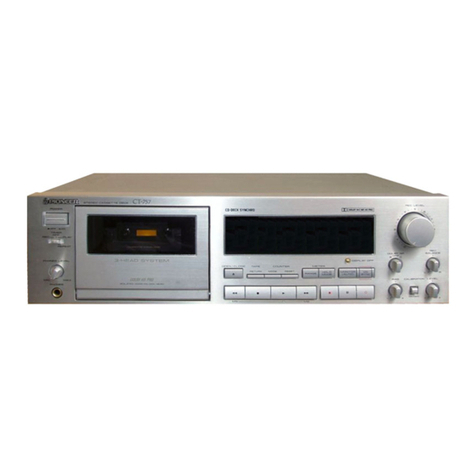
Pioneer CT-S830S User manual

Pioneer

Pioneer CT-S830S User manual

Pioneer CT-W430 User manual

Pioneer

Pioneer CT-W430 User manual

Pioneer CT-W300 User manual

Pioneer

Pioneer CT-W300 User manual

Pioneer CT-40 User manual

Pioneer

Pioneer CT-40 User manual
Pioneer CT-W630R User manual

Pioneer

Pioneer CT-W630R User manual

Pioneer CT-W600R User manual

Pioneer

Pioneer CT-W600R User manual

Popular Cassette Player manuals by other brands

Aiwa HS-RX693 Service manual

Aiwa

Aiwa HS-RX693 Service manual

Sony MEGA BASS CFD-DW83 Service manual

Sony

Sony MEGA BASS CFD-DW83 Service manual

Naxa NPB-277 instruction manual

Naxa

Naxa NPB-277 instruction manual

Aiwa CSD-FD83 Service manual

Aiwa

Aiwa CSD-FD83 Service manual

Sony Walkman WM-EX621 operating instructions

Sony

Sony Walkman WM-EX621 operating instructions

Nakamichi 700 Service manual

Nakamichi

Nakamichi 700 Service manual

Philips turbo drive VR550 Service manual

Philips

Philips turbo drive VR550 Service manual

Panasonic RQSX77V - PERSONAL STEREO operating instructions

Panasonic

Panasonic RQSX77V - PERSONAL STEREO operating instructions

Aiwa RM-P30 Service manual

Aiwa

Aiwa RM-P30 Service manual

Durabrand CT-995 operating instructions

Durabrand

Durabrand CT-995 operating instructions

LG GoldStar GSW-9320 Service manual

LG

LG GoldStar GSW-9320 Service manual

Sanyo M7900K Service manual

Sanyo

Sanyo M7900K Service manual

Aiwa FX-LM99 Service manual

Aiwa

Aiwa FX-LM99 Service manual

Philips NR1012 user guide

Philips

Philips NR1012 user guide

Sony Walkman WM-EX2000 operating instructions

Sony

Sony Walkman WM-EX2000 operating instructions

Panasonic RQ-345 Service manual

Panasonic

Panasonic RQ-345 Service manual

Philips AQ6601 brochure

Philips

Philips AQ6601 brochure

Sony WM-SXF10 operating instructions

Sony

Sony WM-SXF10 operating instructions

manuals.online logo
manuals.online logoBrands
  • About & Mission
  • Contact us
  • Privacy Policy
  • Terms and Conditions

Copyright 2025 Manuals.Online. All Rights Reserved.