Pioneer RG-2 User manual

RG
DYNAMIC
PROCESSOR
1h
pp
2oSBlLT
Mm
MPIONEER'
G-2
OPERATING
INSTRUCTIONS
SPECIFICATIONS
Semiconductors
Ics
4
Transistors
F)
Diodes
30
Processor
Section
Maximum
Output
Vohiage
ON
(Ik,
T-H.D.:0.5%
Ry
:A7K2,
DYNAMIC
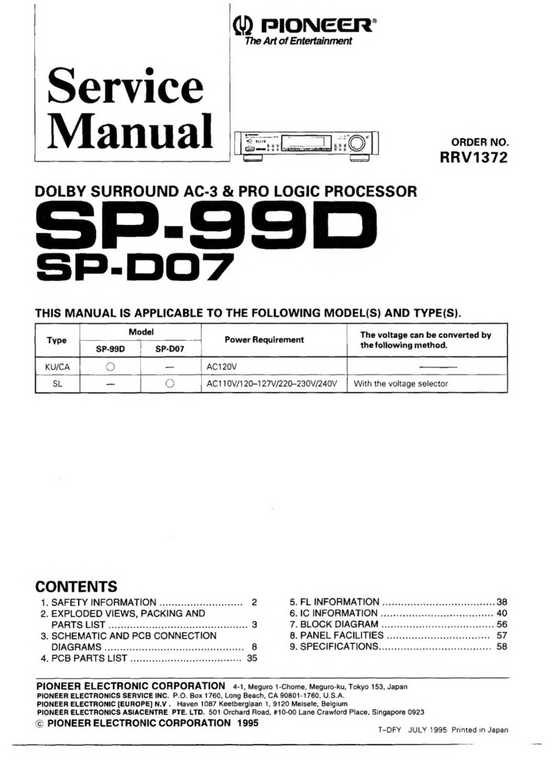
EXPANSION:
16dB)
‘Total
Harmonie
Distortion
0.08%
(Qutput:1¥,
kHz,
DYNAMIC
EXPANSION
1643)
Dynamic
Expansion
4,7,10,
13,1648
Gain
tees
a
DYNAMIC
|
yay
EXPANSION)
Upward
Gain|
+248
[
Dovoward
Impulse
Response
Attack
Time
Release
Time
Input
Impedance
4aB
|
+68
|
+8dB
2B
348
i
T
+10dB
4dB
|
SB
648
03mse:
120msee
SKS?
(20H7
to
20kHa)
Ss
S/G
Before
turning
on
the
power,
please
confirm
the
setting
of
the
line
VOLTAGE
SELECTOR
switch
on
the
rear
panel.
If
it
is
not
set
properly,
change
the
seiting
of
it
according
to
the
LINE
VOLTAGE
SELECTOR
SWITCH
on
page
3.
NOTE:
‘These
operating
instructions
apply
to
two
nersions
of
the
RG-2,
The
KG-2/8/G
model
1s
supplied
with
the
rack
mount
adaptors
as
an
accessory,
while
RG-2/8
model
ie
‘tot
supplied
with
it
How
to
anstall
the
rack
mount
odap-
tore
is
deserdbed
on
page
8
‘Output
Impedance
3000
(1H)
Residual
Noise
roy
(HF
A,
DYNAMIC
EXPANSION:
16d)
‘Signal
to
Noise Ratlo
(IHF
A,
Shortcrcuited,
DYNAMIC
EXPANSION:
1648)
1006
(at
1¥]
116dB
(at
6.5¥)
Miscellaneous
Power
Requirements.
Hovp1zovi220v/240v
(switchable),
50/6042
.
108
1
g20(i)99{11336(D}mm
16:3)
6(W|x3-7/8(1i)x1
3+
/4(D)in
4g
(9Ib
102)
Power
Consumption
Dimensions
Weight
(without
package)
Furnished
Parts
Connection
cord
with
pin
plugs
2
Operating
instructions
Rack
mount
adaptors
(5/6
model
only),
Nore:
Specifications
and
the
design
subject
to
possible
modifica
tion
without
notice
due
to
improvements

CONTENTS
Specifications
........
Li
fOpatition
saceits
caccrtenait
vas
6
Features
2
Using
A
Tape
Deck
é
6
Rear
Pane)
Facilities
8
For
Maximum
Enjoyment
.......
6
Installation
Precautions
3
RG-2Technical
Outline
.........
7
Connections
.
4
chematic
Diagram
.........++++++
Insertion
Front
Panel
Facilities
5
Modern
recording
uses
three
dynamic
control
dynamic
distrotion
in
esch
of
these
areas,
increas
techniques
which
may
detract
from
the
original
ing
the
contrast.
and
virtually
restoring
the
original
dynamic
range;
reduction
of
transient
peaks,
over-
live
program,
In
order
to
obtain
maximum
benefit
all
compression
of
loud
levels
and
upward
mani-
from
this
unit,
please
read
the
following
instru.
pulation
of
soft
levels.
The
RG-2
will
correct
tions
carefully
FEATURES
Broadens
Dynamic
Range
that
lower
frecuency
instruments
are
also
enhanced,
The
dynamic
range
of
the
music
source
can
be
expanded
Design
Oriented
toward
High
S/N
and
Low
by
employing
the
RG-2
asasieren
system
adaptor
unit.
No
Distortion
preprocessing
is
needed
and
only
ordinary
program
sources,
such
as
records,
FM
broadcasts
or
tape
music
ate
requited
‘The
dynamic
range
4s
brcadened
by
upward
and
downs
‘expansion,
resulting
in
a
powerful
and
sharp
rendition
of
¥¢
source.This
has
the
effect
of
bringing
perfortners
right
into
the
listening
room,
and
especially
pulsive
sources
such
as
rock
and
soul
ae
given
a
broad
new
dimension.
The
gain
conticl
amplifier
adopts
low-noise
differentia!
transistors
and low-neise
ICS
for
a
Sgnaktonoise
ratio
of
1004B
and
a
total
harmonic
distortion
of
0.05%
Further
ore,
the
sensor
section
is
also
equipped
with
low-noise
transistors
in
order
to
keep
the
noise
in
the
control
curtent
‘down
to
the
bare
minimum.
S-Stage
Dynamic
Expansion
Selector
‘The
expansion
in
the
dynamic
range
can
be
switehed
in
3dB
steps
from
4B
to
16¢B
with
this
Setting
selector.
By
combining
the
upward
and
downward
expansion,
it
is
possible
to
produce
the
optimum
expansion
in
the
dynamic
range
and
also
to
select
the
expansion
according
to
the
Noise
Reduction
Effect
ruse
soures
and
your
individual
taste,
A
noise
reduction
effect
is
also
included
which
reduces
namic
Expansion
with
Fluroscan
Display
underiying
source
noise.
Tape
hiss,
motor
rumble
and
other
By
mie
soe
ee
background
noisos
are
reduced
by
the
circuit
properties
of
this
unit,
so
that
low
noise,
exciting
stereo
sound
ean
been.
joyed.
Faithful
Reproduction
Funct
The
sensor
section
which
produces
the
control
signal
is
Provided
with
an
energy
cistibuticn
filter,
to
ersure
that
Preserves
Natural
Impression
‘Atiack
and
release
characteristics
of
the
audio
signal
are
preserved
by
a
fast
and
slow
response
(mixed)
double
ac:
ton
control
signal
that
prevents
unnatural
impressions
in
the
reproduced
sound.
Fluroscan
is
incorporated
for
the
meter
which
indicates
the
degree
of
the
dynamic
range's
expansion.
This
new
kind
of
display
accurately
tracks
the
processing
action
and
it
allows
readout
of
the
expansion
at
exch
instantin
dB,
Smart,
Slimly
Designed
Styling
The
processor
has
been
slimly
designed
with
the
dynam
ic
expansion
moter,
which
employs
a
Fluroscan
display,
in
the
center
for
a
clean,
fresh look.
The
height
dimension
of
the
front
panel
conforms
to
the
F1A*
standard
2U
size
format.
Using
the
optional
rack
mount
adaptors
(JA-R1O4),
the
processor
can
be
installed
in
a
rack
confarming
to
ELA,
the
expansion
function
is
not
rigged
by
noise
components,
However,
expansion
is
not
limited
to
instruments,
whose
fundamental
frequency
is
close
to
the
center
frequency
of
the
energy
distribution
filter,
since
all
musical
instruments
Produce
harmonics
which
are
strongest
when
the
insiru-
(Ye
PrOtser
ment
Is
played
hard.
Hence
these
harmonics
activate
the
ene
semsing
citcuit
and
control
the
degree
of
expansion,
so
The
rack
mount
adaptors
are
equipped
withS/0
mode!
6s
2
“EIA:
Electronic
Industries
Association

PIONEER
REAR
PANEL
FACILITIES
fo)
ia
if
@
®
}
@
PROCESSOR
INPUT
JACKS
1.
Prepare
a
medium
size
screwdriver.
‘Connect
these
jacks
10
the
TAPE
REC
jacks
on
the
stereo
2
Insort
the
screwdriver
into
the
arrow
on
the
voltage
amplifier
or
o
the
PREAMP
OUT
(OUTPUT)
jacks
on
the
selector
and
adjust
so
that
the
tip
of
the
arrow
points
pebeaatin
to
the
voltage
value
of
your
area
as
shown
below.
PROCESSOR
OUTPUT
JACKS
een
Connect
these
jacks
10
the
TAPE
PLAY
jacks
on
the
siereo
amplifier
or
tw
the
POWER
AMP
IN
(INPUT)
jacks
on
the
power
amplifier.
@®
TAPE
REC
JACKS,
f
Connect
these
16
the
INPUT
(REC)
jackson
the
tape
deck
p
@
TAPE
PLAY
JACKS
™
sexencsives
Connect
these
to
the
OUTPUT
(PLAY)
jacks
on
the
tape
deck,
©
ACOUTLET
®
LINE
VOLTAGE
SELECTOR
SWITCH
‘This
s
an
auxiliary
power
outlet.
Connect
the
power
plug
‘Check
that
the
indication
of
the
switch
is
same
as
your
‘of
your
tape
deck
oF
other
stefeo
hi-fi
component
to
this
residence
before
plugging
the
power
cord
into
the
outlet
‘outlet.
Ic
is
not
coupled
with
the
power
switch
on
the
I
it
ist
or
if
you
move
to
an
area
where
the
voltage
model
RG-2
(UNSWITCHED],
The
maximum
power
ca:
requirements
differ,
change
the
switch
setting
as
follows,
pacity
's
1O0W
and
so
do
not
connect
electrical
appliances
Before
adjusting,
disconnect
the
power
cord
‘with
a
power
capacity
exceeding
this
value
INSTALLATION
PRECAUTIONS
‘To
ensure
the
best
sound
quality
and
touble-tree
operation,
avoid
setting
up
the
RG
dynamic
processor
in
any
of
the
locations
described
below:
‘Locations
lable
o
downgrade
parformence
Resulting
vouble
1
Leeatons
expaaed
e
direct
suriight,
or
naar
heaters
1
sternal
heat
causes
dha
perlornance
ofthe
latranie
pare
to
‘eteriorae,
and
operation
becomes
unstadte
2.
Locations
with
poor
ventilation,
with
hich
humidity
or
mois-
|
2,
Caute
of
faulty
contact
in
inout-outeut
terminal,
and
vst.
|
‘ure
contents,
oF
dusty
Lecavons
‘High
nomidity
and
a
igh
molrtor
cortent
caste
deteriorston
Jn
insulation,
‘Thar
ie
ao
tho
dangor
of
eurent
loskage
end
heat
eeneretion
in
the
ctcut
pars,
Dust
or
arouse
in
the
rota
5.
Locations
suscaptbve
to
vibration
3.
These
locations
efost
tne
precsion
pars
aavessly

CONNECTIONS
CONNECTION
DIAGRAM
Turntable
Tuner
Tope
deck
[eae
Toput
|
[Outeoe
=r
©
"00108000
Stereo
arplitien
‘Spear
‘Sponker
FY
CONNECTIONS
TO
STEREO
AMPLIFIER
Site
amolitir
Use
the
accessory
connecting
cords
to
connect
the
2
PROCESSOR
INPUT
and
PROCESSOR
OUTPUT
Jacks
on
the
RG-2
to
the
TAPE
REC
and
TAPE
PLAY
jacks
on
a
stereo
amplifier
(Pig.
1).
Take
care
not
to
reverse
L
(left)
and
R
(right)
channels,
and
make
sure
connections
securely
‘TAPE
DECK
CONNECTIONS
Since
the
RG-2
is
connected
to
the
TAPE
REC
and
PLAY
jacks
of
the
stereo
amplifier,
a
tape
recorder
cannot
be
connected
if
the
stereo
amplifier
is
pro-
vided
with
only
one
set
of
tape
jacks.
In
this
case,
connect
the
input
and
output
jecks
of
the
tape
deck
to
the
TAPE
REC
and
PLAY
jacks
of
the
RG2
Connections
for
recording
Connect
the
recording
input
jacks
(INPUT)
on
the
tape
deck
to
the
TAPE
REC
jacks
on
the
RG.2.
Conneetions
for
playback
Connect
the
playback
output
jacks
(OUTPUT)
on
the
tape
deck
to
the
TAPE
PLAY
jacks
on
the
RG2
Faaorcng
onTaTTOE
‘wes
Fig.
1

FRONT
PANEL
FACILITIES
OQ ®@
@
®
BIONEER
(ft
@
POWER
SWITCH
Power
is
supplied
to
the
model
RG-2
when
this
switch
is
depressed,
The
power
Indicator
comes
on
2s
soort as
the
ower
Is
supalied,
®
POWER
INDICATOR
This
comes
on
as
soon
as
the
RG-2's
power
switch
|S
Set
to
ON
to
indicate
that
power
i
being
supplied.
@
DYNAMIC
EXPANSION
METER
This
meter
allows
you
to
read
out
the
gain
boest
with
respect
to
the
Input
signal
In
cecibels.
(See
additional
description
on
page
6).
@
DYNAMIC
EXPANSION
INDICATORS.
The
4aB,
768,
10dB, 1348,
1646
indicators
light
up
in
accordance
with
the
position
of
the
dynamic
expansion
selector.
®
PROCESSOR
SWITCH
Depress
this
switch
(ON)
to
produce
an
expansion
effect
with
the
signals
fed
from
the
PROCESSOR
INPUT
jacks,
The
dynamic
expansion
indicator
will
come
on,
and
signals
featuring
an
expansion
effect
only
will
be
fed
out
from
the
model
RG-2’s
OUTPUT
jacks.
in
the
OFF
pos:
ton,
the
RG-2
circuitry
is
bypassed.
This
position
allows
for
instant
comparison
between
the
expanded
and
te
un
processed
signals
NOTE:
Whon
the
RG-2'
power
aitch
is
set
10
the
OFK
post
tion
and
the
processor
switch
Is
also
set
to
OFF,
the
signal
whioh
has
bypassed
the
procesior
ereuitry
is
made
valeble
ai
the
OUTPUT
jacks,
There
will,
however,
be
to
output
if
the
input
level
control
is
set
fo
the
‘0!
post
Vian.
Make
sure
that
this
control
te
set
to
the
‘10
Dost-
@
TAPE
MONITOR
INDICATOR
This
comes
on
when
the
tape
mi
TAPE
MONITOR
SWITCH
Depress
this
switch
to
monitor
the
sound
on
the
tape
as
it
's
being
recorded
or
when
playing
back
a
tape
using
a
wpe
deck
connected
to
the
RG-2's
TAPE
jacks.
(The
tape
‘monitor
indicator
comes
on.)
Set
the
switch
to
OFF
when
@®
DYNAMIC
EXPANSION
SELECTOR
This
selector
selects
maximum
gain
boost
value
with
re-
spect
to
the
input
level,
i.e:
ratio
of
gain
increase
be
‘ween
large
input
signal
and
small
input
signal.
Maximaura
gain
boost
increases
as
the
sclector
is
tamed
clockwise.
Set
the
selector
to
the
most
desirable
position
while
listening
to
the
reproduced
sound
itor
switch
isdepressed.
Dynamic
Expansion
Dynamic
expantion
is
defined
o%
the
sum
of
the
down
tward
expansion
(where
amail
inputs
ere
expanded
down)
‘and
upland
expansion
(where
lenge
impute
are
expanded
up|.
For
details,
refer
10
“Technical
Outline"
on
pase
7.
@
INPUT
LEVEL
CONTROL
Use
this
control
to
adjust
the
input
level
at
which
the
ox
pansion
effect
is
initiated.
Clockwise
rotation
increases
the
expansion
with
rospoct
to
small
signal
levels
jinereases
expansion
sensitivity),
Adjust
the
control
for
desired
effect
according
to
program
source

2
OPERATION
PRIOR
TO
SWITCHING
POWER
ON
Set the
controls
and
switches
to
the
following
posi-
tions
before
operating
the
model
RG-2.
L,
Set
the
dynamic
expansion
selector
to
10.
2,
Set
the
input
level
control
to
the
center
position
(5).
3,
Set
the
tape
monitor
switch
to
OFF
(released).
4,
Set
the
processor
switch
to
OFF
(released).
5,
Set
the
tape
monitor
switeh
(which
is
related
to
the
‘TAPE
jacks
connecting
the
RG-2)
on
the
stereo
amplifier
to
ON.
OPERATION
PROCEDURE
1,
Play
the
program
source
on
the
stereo
amplifier,
and
listen
to
the
sound
without
the
expansion
effect.
2,
Depress
the
processor
switch
(ON).
3.
Rotate
the
input
level
control
and
set
it
so
that
the
indication
on
the
dynamie
expansion
meter
is
brought
to
its
widest.
For
instance,
when
the
dynamic
expansion
selector
is
set
to
the
‘10’
position,
adjust
so
that
the
display
indiestes
up
to
10
when
a
high
input
signal
is
fod
in
(See
Fig.
3)
4.
Adjust
the
volume
control
on
the
stereo
ampli-
fier
for
suitable
volume,
5.
Operate
the
dynamic
expansion
selector
and
set
it
to
the
position
(4,
7,
10,
13,
18)
where
the
desired
expansion
is
obtained
6,
Adjust
the
volume
and
tone
controls
on
the
stereo
amplifier
for
desired
volume
and
tone,
Fig.
3
USING
A
TAPE
DECK
By
setting
the
tape
monitor
switch
on
the
stereo
amplifier
to
ON,
and
the
processor
switeh
on
the
RG-2
to
OFF,
the
tape
monitor
switch
on
the
RG-
2
ean
be
operated
in
place
of
that
on
the
stereo
amplifier.
The
signal
at
the
RG-2
TAPE
REC
jacks
bypasses
the
processor.
‘When
Employing
the
Processor
for
Tape
Playback
1.
Depress
the
tape
monitor
switch
(ON).
2,
Depress
the
processor
switch
(ON),
3.
Other
operations
are
the
same
as
deseribed
in
“OPERATION”.
FOR
MAXIMUM
ENJOYMENT
RG-2
EFFECT
ON
MUSIC
SOURCE
‘The
RG-2
increases
the
level
variations
in
the
music
source,
High
level
and
percussive
material
such
2s
jazz
and
rock
are
best
played
at
the
dynamic
ex~
pansion
selector
settings
of
10, 18,
16dB, while
delicate
music
such
as
instrumental
soles
and
chamber
music
can
be
given
an
unnatural
effect
if
too
much
expansion
is
used,
so
the
4
to
L0dB
sot-
tings
are
recommended
for
this
type
of
program
Other
factors
such
as
room
acoustics
also
affect
the
choice
of
setting,
but
wits
the
range
of
sottings
provided
almost
all
recorded
material
will
benefit
from
the
unique
processing
available
in
this
unit,
Changes
in
the
ambience
‘The
RG-2
serves
to
expand
the
dynamic
range
of
the
music
source.
Whenever
there
is
a
difference
be-
tween
the
levels
of
the
left-and
right:
channet
input
signals,
this
difference
is
expanded.
Say,
for
instance,
the
difference
between
the
left
and
right
levels
is
24B,
This
is
expanded
to
4¢B
or
BAB.
This
in
turn
translates
into
a
change
in
the
ambience
of
the
sound
as
heard
by
the
listener.
With
a
music
source
arranged
like
that
in
Fig.
3,
an
intoresting
effect
is
obtained
whozeby
the
position
of
the
vocalist
at
the
center
moves
to
the
left
and
right
along
with
the
fluctuations
in
the
difference
between
the
left:
channel
(bass)
snd
right
channel
(piano)
sf
METER
INTERPRETATION
The
meter
indicates
the
instantaneous
maximum
dynamie
expansion
amount
in
dB.
Maximum
moter
deflections
are
4,
7,
10,
13,
16dB
according
to
the
dynamic
expansion
selector
setting.
Partial
mixing
of
L
and
R
channel
signals
causes
both
meters
to
deflect
even
with
only
one
channel
input.
How-
ever,
the
separation
does
not
change
with
stereo
reproduction.

RG-2
TECHNICAL
OUTLINE
‘The
basic
funetion
of
the
RG-2
is
to
expand
the
level
variations
of
the
input
signal
(see
Fig.
5:
in-
pul-output
transfer
characteristics),
Due
to
the
ex-
pander
circuit
composition,
the
input
and
output
clreults
are
not
necessarily
linear.
‘The
block
diagram
is
shown
below.
The
circuit,
consists
mainly
of
a
flat
frequency
response
gain
control
amplifier
(GCA)
and
sensor
section
which
produces
the
signal
to
control
the
gain
of
the
gain
control
amplifier,
After
passing
through
the
input
level
control
and
buffer
amplifier,
a
portion
of
the
input
signal
goes
to
the
sensor
section.
At
the
sensor
section,
the
signal
first
passes
through
an
energy
distribution
filter,
which
possesses
a
slope
of
~6dB/octave
above
and
below
a
2,
5kHz,
center
frequency.
This
effectively
reduces
noise
components,
such
as
motor
rumble,
bum
and
tape
hiss,
yielding
only
the
center
frequeney
com-
ponent,
At
the
RG
detector,
a
peak
detector
(ripple
cancelling
type)
produces
a
DC
output
pro-
portional
to
the
peak
values
of
the
AC
input
signal.
The
output
from
this
RG
detector
becomes
the
gain
control
signal
for
the
GCA.
Current
from
the
sensor
section
determines
the
opentoop
gain
of
the
gain
control
amplifier,
The
gain
therefore
increases
as
the
control
current
in-
creases
in
accordance
with
the
input
signal.
‘The
characteristics
of
this
signal
undergo
changes
sue
as
those
in
Fig.
6:
input-gain
characterissics.
To
provide
this
characterisiivs,
an
NFB
(negative
back)
circuit
returns
a
portion
of
the
GCA
output
to
the
input,
and
the
dynamic
expansion
selector
selects
the
NFB
elements
to
control
the
feedback
ratio,
thereby
determining
the
total
gain
(Fig.
6).
jjmme-
>
Econo
vee
oe
nw
al
PIONEER
Loft
and
right
channels
are
mixed
by
a
blending
re-
sistor
at
the
sensor
seetion
input,
to
provent
e:
cessive
gain
difference
between
the
channels
from
producing
an
unnatural
effect
during
stereo
play-
back.
sao
prey
—
|
q
:
i
i
Fig.
5:
RG
processor
input-output
transfer
characteristics
Ell
Fig.
6:
RG
processor
input-gein
characteristics

SE
FIN
FEY
MOUNTING
THE
RACK
MOUNTING
ADAPTORS
(Applicable
5/G
model
only)
If
you
mount
the
accessory
rack
mount
adaptor
onto
the
RG-2,
you
will
be
able
to
install
the
RG-2
into
a
rack
designed
to
meet
EIA
standards
(ikke
the
Pioneer
JA-R2S)
with
a
2
unit
mounting
piteh.
Mounting
Procedure
1.
Detach
the,rubber
bushes
from
both
sides
of
the
RG-2,
2,Secure
the
rack
mount
adaptors
onto
the
side
pancls
with
the
accessory
mounting
scrows
(MAx10}.
(Fig.
8)
Rack
Mounting
1,
Remove
the
rubber
fect
(4)
from
the
RG.2,
using
a
Phillips
serowdriver
(this
is
not
necessary
if
you
leave
a
gap
between
the
components).
2,
Insort
the
RG-2
and
align
with
the
BLA
standard
mounting
holes
(mounting
pitch:
2U).
8,
Serew
the
RG-2
into
place
using
the
accessory
oval
countersunk
serews
(M5x16),
angular
washers
and
plastic
rings
(four
of
each)
and
a
Phillips
screwdriver.
Nore:
The
reck
mount
adeptors
are
$
mm
thick.
When
aligning
them
with
other
Pioneer
stereo
components
with
2
thick
ness
of
§
mm,
slide
the
accessors
spacers
behind
the
‘adapters
and
then
attach
(Fig,
9)
Flack
mount
asepter.
a
Py
~
eee
ao
=
Mounting
stew
Fig.
8
Aseacer)
Plastic
ino
aG2
Fig.
9
List
of
Parts
for
Rack
Mount
Adaptor
Mounting
screws
(M4x10);
4,
Oval
countersunk
serews
(MBX16);
4,
Angular
washers;
4,
Plastic
rings;
4,
Spacers
(t:
2mm);
4,
PIONEER
ELECTRONIC
CORPORATION
ONEER
ELECTRONICS
AUSTHALIA
PTY.
LIE.
1
«<p0A03§509
4-1,.Meguro
7-Gnome,
tvaguro-ku,
Tokyo.
153.
vepan
Printed
in
Japan
(ARE-3230)
Table of contents
Other Pioneer Computer Hardware manuals
Pioneer
Pioneer DEQ-P7650 User manual

Pioneer
Pioneer DEQ-P7050 User manual

Pioneer
Pioneer AVG-VDP1 User manual

Pioneer
Pioneer DEQ-P800/UC User manual
Pioneer
Pioneer DEQ-7200 User manual
Pioneer
Pioneer SP-99D User manual

Pioneer
Pioneer RMD-V3000X User manual

Pioneer
Pioneer DEQ-P7050 User manual

Pioneer
Pioneer AXY1153 User manual
Pioneer
Pioneer DEQ-P7650 User manual