manuals.online logo
Brands
  1. Home
  2. •
  3. Brands
  4. •
  5. Pioneer
  6. •
  7. Tuner
  8. •
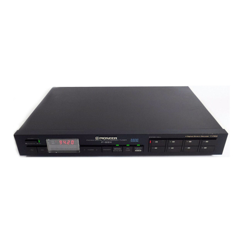
  9. Pioneer F-551L User manual

Pioneer F-551L User manual

FM/AM
DIGITAL
SYNTHESIZER
TUNER
DIGITALER
UKW/MW-SYNTHESIZER-TUNER
SYNTONISEUR
SYNTHESISEUR
A
AFFICHAGE
NUMERIQUR
FM/AM
SINTONIZZATORE
FM/AM
DIGITALE
SINTETIZZATO
F-551L
F-55171
Operating
Instructions
Bedienungsanlestung
Mode
d'emploi
Istruzioni
per
fuso
Model
designed
exclusively
for
use
in
Italy/
Modello
progettato
esclusivamente
per
|'Italia
©
PIONEER
on
an
cara,
erremzes
Ten
ESS1
©
The
illustration
shows
the
model
F-551.
Thank
you
for
buying
this
Pioneer
product.
Please
read
through
these
operating
instructions
so
you
will
know
how
to
operate
your
model
properly.
After
you
have
finished
reading
the
instructions,
put
them
away
in
a
safe
place
for
future
reference.
In
some
countries
or
regions,
the
shape
of
the
power
plug
and
power
outlet
may
sometimes
differ
from
that
shown
in
the
ex-
planatory
drawings.
However,
the
method
of
connecting
and
operating
the
unit
is
the
same.
WARNING:
ro
prevent
FIRE
OR
SHOCK
HAZARD,
DO
NOT
EXPOSE
THIS
APPLIANCE
TO
RAIN
OR
MOISTURE.
IMPORTANT
NOTICE
[For
U.S.
and
Canadian
models]
The
serial
number
for
this
equipment
is
located
on
the
rear
panel.
Please
write
this
serial
number
on
your
enclosed
war-
ranty
card
and
keep
it
in
a
secure
area.
This
is
for
your
securi-
ty.
[For
Canadian
model]
CAUTION:
to
prevent
ELECTRIC
SHOCK
DO
NOT
USE
THIS
(POLARIZED)
PLUG
WITH
AN
EXTENSION
CORD,
RECEPTACLE
OR
OTHER
OUTLET
UNLESS
THE
BLADES
CAN
BE
FULLY
INSERTED
TO
PREVENT
BLADE
EXPOSURE.
ATTENTION:
pour
prevenir
LES
CHOCS
ELEC-
TRIQUES
NE
PAS
UTILISER
CETTE
FICHE
POLARISEE
AVEC
UN
PROLONGATEUR
UNE
PRISE
DE
COURANT
OU
UNE
AUTRE
SORTIE
DE
COURANT,
SAUF
SI
LES
LAMES
PEUVENT
ETRE
INSEREES
A
FOND
SANS
EN
LAISSER
AUCUNE
PARTIE
A
DECOUVERT.
CONTENTS
Features
v:
sasssnnsanosnaxcoavanawaisacevweaswansasasannnaicnas
ae
anes
3
Presetting
FM
and
AM
(MW
or
LW)
Stations
.............+
Checking
the
Accessories
............cseseeeescceeenteoneneenees
3
Hints
for
Better
Reception
..........ccceceeseeeseneeeeesenenneee
CONNECHONS!
.csainsvecenencs
ca
dazas
nett
cANtNNSE
dee
ewene
vecnes
4
Troubleshooting
ssssscsessvics
mvswesenss
ss
savarcaniasesasvannsns
+
FrOnE€
Panel
FaGiti@S
scscges
capsesssacnemneysegeeoreaeeen
ween
5
SDECIICAUONS
ssiccits
scicsciomvncomesneeian
ainiseinnuwiaaasiocasaennmectione
Listening
to
Broadcasts
..........ceeeeceeseeee
eee
eeeeeeneeeteeee
6
LINE
VOLTAGE
SELECTOR
SWITCH
Only
multi-voltage
models
are
provided
with
this
switch.
U.S.,
Canadian,
European,
U.K.,
and
Australian
models
are
not
provided
with
this
switch.
The
line
voltage
selector
switch
is
on
the
rear
panel.
Before
your
model
is
shipped
from
the
factory,
this
switch
is
set
to
the
power
requirements
of
the
destination.
Check
that
it
isset
properly
before
plugging
the
power
cord
into
the
AC
outlet.
If
the
voltage
is
not
properly
set
or
if
you
move
to
an
area
where
the
voltage
requirements
differ,
adjust
the
selector
switch
as
follows.
1.
Use
a
medium-size
screwdriver.
2.
Insert
the
screwdriver
into
the
groove
on
the
voltage
seec-
tor,
and
adjust
so
that
the
tip
of
the
arrow
points
to
the
voltage
value
of
your
area.
Lov
|
240V
VOLTAGE
SELECTOR
Medium-size
screwdriver
QPIONEER’
FRANCAIS
DEUTSCH
Iam
ENGLISH
i=]
=
=
al
5
2
READ
INSTRUCTIONS
—
All
the
safety
and
Operating
instructions
should
be
read
before
the
appliance
is
operated.
RETAIN
INSTRUCTIONS
—
The
operating
instruc-
ttons
should
be
retained
for
future
reference.
HEED
WARNING
—
All
warnings
on
the
appliance
and
in
the
operating
instructions
should
be
adhered
to.
FOLLOW
INSTRUCTIONS
—
All
operating
and
use
instructions
should
be
followed.
WATER
AND
MOISTURE
—
The
appliance
should
not
be
used
near
water
—
for
example,
near
a
bathtub,
washbow/l,
kitchen
sink,
laundry
tub,
ina
wet
basement,
or
near
a
swimming
pool,
etc.
LOCATION
—
The
appliance
should
be
installed
in
a
stable
location.
WALL
OR
CEILING
MOUNTING
—
The
appliance
should
not
be
mounted
to
a
wail
or
ceiling.
VENTILATION
—
The
appliance
should
be
situated
so
that
its
!ocation
or
position
does
not
interfere
with
its
proper
ventilation.
For
example,
the
ap-
pliance
should
not
be
situated
on
a
bed,
sofa,
rug,
or
similar
surface
that
may
block
the
ventilation
Openings:
or,
placed
in
a
built-in
installation,
such
as
a
bookcase
or
cabinet
that
may
impede
the
flow
of
air
through
the
ventilation
openings.
HEAT
—
The
appliance
should
be
situated
away
from
heat
sources
such
as
radiators,
heat
registers,
stoves,
or
other
appliances
(including
amplifiers)
that
produce
heat.
POWER
SOURCES
—The
appliance
should
be
connected
to
a
power
supply
only
of
the
type
described
in
the
operating
instructions
or
as
marked
on
the
appliance.
POWER-CORD
PROTECTION
—
Power-supply
cords
should
be
routed
so
that
they
are
not
likely
to
be
walked
on
or
pinched
by
items
placed
upon
or
against
them,
paying
particular
attention
to
cords
at
plugs,
convenience
receptacles,
and
the
point
where
they
exit
from
the
appliance.
POLARIZATION
—
If
your
purchased
product
is
provided
with
a
polarized
power
plug,
please
read
the
following
instructions.
This
product
is
equipped
with
a
polarized
alternating
current
line
plug
(a
plug
having
one
blade
wider
than
the
other).
This
piug
will
fit
into
the
power
outlet
only
one
way.
This
is
a
safety
feature.
If
you
are
unable
to
insert
the
plug
fully
into
the
outlet,
try
reversing
the
plug.
If
the
plug
should
still
fai!
to
fit,
contact
your
electrician
to
replace
your
obsolete
outlet.
Do
not
defeat
the
safety
purpose
of
the
polarized
plug.
CLEANING
—
The
appliance
should
be
cleaned
only
with
a
polishing
cloth
or
a
soft
dry
cloth.
Never
clean
with
furniture
wax,
benzine,
insecticides
or
other
volatile
liquids
since
they
may
corrode
the
cabinet.
IMPORTANT
1
The
tightning
flash
with
arrowhead,
within
an
equi-
jateral
triangle,
is
intended
to
alert
the
user
of
the
presence
of
uninsulated
“dangerous
voltage”
within
the
product's
enclosure
that
may
be
of
sufficient
magnitude
to
constitute
a
risk
of
electric
shock
to
persons.
IMPORTANT
2
tf
the
apparatus
is
fitted
with
AC
mains
power
out-
let(s),
see
REAR
PANEL
FACILITIES
for
convenient
connection
of
additional
Hi-Fi
component(s).
Make
all
connections
to
the
AC
outlet(s)
and
the
signal
terminals
first.
Connect
the
plug
to
the
wali
socket
last,
make
sure
that
the
power
switch
is
off.
Discon-
Nect
the
wall
plug
when
the
equipment
is
not
in
(regular)
use,
e.g.
when
on
vacation.
<ARE1048>
SERVICE
ENTRANCE
€QUIPMENT
POWER
LINES
—
An
outdoor
antenna
should
be
located
away
from
power
lines.
NONUSE
PERIODS
—The
power
cord
of
the
appliance
should
be
unplugged
from
the
outlet
when
left
unused
for
a
long
period
of
time.
OBJECT
AND
LIQUID
ENTRY
—
Care
should
be
taken
so
that
objects
do
not
fall
and
liquids
are
not
spilled
into
the
enclosure
through
openings.
DAMAGE
REQUIRING
SERVICE
—
The
appliance
should
be
serviced
by
a
Pioneer
authorized
ser-
vice
center
or
qualified
service
personnel
when:
The
power-supply
cord
or
the
plug
has
been
damaged:
or
Objects
have
fallen,
or
tiquid
has
been
spilled
into
the
appliance:
or
The
appliance
has
been
exposed
to
rain:
or
The
appliance
does
not
appear
to
operate
nor-
mally
or
exhibits
a
marked
change
in
perfor-
mance;
or
@
The
appliance
has
been
dropped;
or
the
enclosure
damaged.
SERVICING
—
The
user
should
not
attempt
to
service
the
appliance
beyond
that
described
in
the
Operating
instructions.
For
all
other
servicing,
contact
the
nearest
Pioneer
authorized
service
center.
POWER
LINES
SERVICE
ENTRANCE
CONDUCTORS,
GROUND
GROUND
WIRE
a,b
CLAMPS
SAFETY
INSTRUCTIONS
OUTDOOR
ANTENNA
GROUNDING
—
If
an
out-
side
antenna
is
connected
to
the
antenna
termi-
nai,
be
sure
the
antenna
system
is
grounded
so
as
to
provide
some
protection
against
voltage
surges
and
built
up
static
charges.
In
the
U.S.A.
section
810
of
the
National
Elec-
trical
Code,
ANS!I/NFPA
No.
70-1984,
provides
information
with
respect
to
proper
grounding
of
the
mast
and
supporting
structure,
grounding
of
the
lead-in
wire
to
an
antenna
discharge
unit,
size
of
grounding
conductors,
location
of
antenna-
discharge
unit,
connection
to
grounding
elec-
trodes,
and
requirements
for
the
grounding
elec-
trode.
See
Fig.
A.
Use
No.
10
AWG
(5.3mm?%)
cop-
per.
No.
8
AWG
(8.4
mm?)
alu-
minum,
No.
17
AWG
(1.0
mm?)
copperclad
steel,
bronze
wire,
or
larger
as
ground
wire.
Secure
antenna
lead-in
and
ground
wires
to
house
with
stand-off
insulators
spaced
from
4
feet
(1.22
meters)
to
6
feet
(1.83
meters)
apart.
Mount
antenna
discharge
unit
as
closely
as
possible
to
where
lead-
in
enters
house.
Use
jumper
wire
not
smaller
than
No.6
AWG
(13.3
mm?)
copper,
or
the
equivalent,
when
a
sepa-
rate
antenna-grounding
electrode
is
used.
See
NEC
Section
810-21
(j).
STAND-OFF
INSULATORS
b
ANTENNA
LEAD-IN
WIRE
TO
EXTERNAL
ANTENNA
TERMINALS
OF
PRODUCT
ANTENNA
DISCHARGE
UNIT
c
GROUND
WIRE
a.b
GROUND
POWER
SERVICE
GROUNDING
ELECTRODE
SYSTEM
(e.g.
interior
metal
water
pipe)
eg)
==
CLAMPS
OPTIONAL
ANTENNA
GROUNDING
ELECTRODE
DRIVEN
8
FEET
(2.44
m)
BONDING
JUMPER
d
(INTO
THE
EARTH
iF
REQUIRED
BY
LOCAi
CODES
SEE
NEC
SECTION
810.21
(f).
CAUTION
RISK
OF
ELECTRIC
SHOCK
®O
NOT
OPEN
CAUTION:
TO
PREVENT
THE
RISK
OF
ELECTRIC
SHOCK,
DO
NOT
REMOVE
COVER
(OR
BACK).
NO
USER-SERVICEABLE
PARTS
INSIDE.
REFER
SERVICING
TO
QUALIFIED
SERVICE
PERSONNEL,
FOR
USE
IN
THE
UNITED
KINGDOM
The
wires
in
this
mains
lead
are
coloured
in
accor-
dance
with
the
following
code:
Biue:
Neutral
Brown:
Live
The
exclamation
point
within
an
equilaterd
tr
tangle
is
intended
to
alert
the
user
of
the
presence
¢
inmportant
operating
and
maintenance
(servicing)
insrucctions
in
the
literature
accompanying
the
appliance
As
the
colours
of
the
wires
in
the
mains
2acd
of
this
apparatus
may
not
correspond
with
th:
coloured
marking
identifying
the
terminals
in
your
plig
proceed
as
follows:
The
wire
which
is
coloured
blue
must
be
Cmn
ected
to
the
terminal
which
is
marked
with
the
ktrer
N
or
coloured
black.
The
wire
which
is
coloured
brown
must
beso
mnected
to
the
terminal
which
is
marked
with
theler
ter
L
or
coloured
red.
Equipment
sold
in
the
U.K.
is
not
supjieed
with
a
power
plug.
FEATURES
CCTS
(Computer
Controlled
Tuning
System)
tuning
for
optimum
sound
quality
e
Reduces
tracking
errors
when
you
are
receiving
FM
and
AM
broadcasts.
®
Auto
high
blend
ensures
optimum
stereo
reception
at
all
times.
¢
Provides
a
digital
indication
of
the
electric
field
strength
of
the
received
broadcast.
Random
24-stations
presetting
Model
F-551
A
total
of
24
FM
and
AM
stations
can
be
preset
into
the
memory
circuit.
Model
F-551L
A
total
of
24
FM,
MW
and
LW
stations
can
be
preset
into
the
memory
circuit.
CHECKING
THE
ACCESSORIES
AM
loop
antenna
FM
T-type
antenna
Connection
cord
with
1
nec
nte
eeu
neeeneneeas
1
Pin
PlUGS
......0ceeeseeeee
1
3
<AREA8>
}
}
|
CONNECTIONS
©
Use
for
FM
reception
un-
til
a
special-purpose
FM
antenna
is
installed.
©
Stretch
both
ends
taut
and
affix
to
a
wall,
etc.
Accessory
FM
Outdoor
FM
AM
LOOP
ANTENNA
T-type
antenna
antenna
®
Unfold
all
four
legs
of
the
AM
loop
antenna
:
toward
the
outside,
and
insert
the
stopper
inside
the
legs
into
the
hole
in
the
AM
loop
antenna
to
fix
it
in
position.
Set
the
antenna
on
a
level
surface,
and
point
in
the
direction
that
gives
optimum
reception.
Do
not
install
the
antenna
in
locations
where
it
touches
the
cover
of
the
unit
or
other
metal
objects,
or
near
a
CD
player,
personal
computer,
or
television
set.
Stretch
taut
and
affix.
Accessory
AM
Loop
Antenna
CONNECTING
THE
FM
T-TYPE
ANTENNA
AND
AM
LOOP
ANTENNA
ll
1.
Strip
the
end
of
the
wires.
2.
Wrap
the
end
of
the
wire
in
a
clockwise
direction
around
the
base
of
the
terminals
and
tighten
the
terminals
to
secure.
The
OUTPUT
jacks
of
this
unit
are
dull
tin-plated,
aiming
at
high
audio
quality.
g~
Antenna
ground
|
Although
grounding
is
not
always
necessary
for
reception,
it
is
recom-
mended
for
protection
against
damage
from
lightning
if
an
outdoor
FM
antenna
is
used.
Grounding
is
recommended
as
well
to
help
reduce
noise
and
hum.
Connecting
the
power
cord
NOTE:
Never
make
the
ground
connection
to
a
gas
pipe
as
sparks
could
Plug
the
power
cord
into
cause
the
gas
to
ignite.
(UNSWITCHED)
the
auxiliary
power
outlet
on
the
amplifier
or
into
an
AC
wall
socket.
\
Pin
plug
connecting
cord
*
Connect
the
white
plug
to
the
white
terminal
(L)
and
the
red
plug
to
the
red
terminal
(R).
¢
Make
sure
that
there
is
a
proper
connection.
White
plug
\S
a
Red
plug
Stereo
amplifier
i
se
ag
i
4
<ARE1048>
FRONT
PANEL
FACILITIES
POWER
switch
When
this
switch
is
set
to
the
on
position,
power
is
supplied
to
the
tuner’s
main
circuits.
The
POWER
unit’s
switch
is
geared
to
selec-
|
ting
the
transformer’s
secondary
so
that
even
in
stand-by
position,
|
the
unit's
circuitry
will
work
as
long
as
the
power
cord
is
connected
’
to
a
power
outlet.
Disconnect
the
power
cord
from
the
power
outlet
when
you
do
not
plan
to
use
the
unit
for
a
jong
period
of
time.
FM
MONO
switch
Normally,
when
receiving
an
FM
stereo
broadcast,
leave
this
switch
OFF.
If
the
broadcast
station
is
distant,
or
if
you
are
in
a
poor
recep-
tion
area,
the
input
signals
will
be
weak,
and
during
stereo
recep-
tion,
noise
will
be
prominent,
making
the
broadcast
difficult
to
hear.
in
such
a
case,
press
ON
this
switch.
The
broadcast
will
be
reproduced
in
monaural,
however
noise
will
be
reduced,
enabling
NOTE:
the
broadcast
to
be
heard
more
clearly.
;
The
memory
will
be
backed
up
so
long
as
the
power
cord
is
not
NOTE:
unplugged.
¢
This
switch
does
not
function
when
you
are
listening
to
an
AM
If
the
power
cord
is
unplugged,
the
memory
will
be
retained
for
several
days.
(MW
or
LW)
broadcast.
©
The
ON
or
OFF
status
of
the
FM
MONO
switch
will
be
memorized
when
you
preset
a
station
in
the
STATION
CALL
switch.
By
using
the
PRESETTING
FM
AND
AM
(MW
or
LW)
STATIONS
function,
you
can
receive
an
FM
broadcast
at
any
time
in
the
same
mode.
t
MEMORY
switch
This
is
used
to
memorize
stations.
When
the
switch
is
pressed,
the
—{
frequency
indication
on
the
frequency
display
flashes.
To
memorize
the
frequency
of
any
station,
press
the
STATION
CALL
switch
while
the
frequency
indication
on
the
frequency
display
flashes.
CCTS
switch
(Computer
controlled
tuning
system)
When
this
switch
is
set
to
ON
(the
CCTS
indicator
lights),
the
unit's
built-in
microcomputer
automatically
performs
the
optimum
tuning
for
the
station
received.
STATION
CALL
switches
These
are
used
to
preset
and
recall
broadcasting
stations.
p g
Frequency
display
ENGLISH
“i888
Ge:
STANDBY
/ON
POWER
e
Illustration
shows
model
F-551.
Operation
indicators
a
TUNED
indicator
This
lights
up
to
indicate
when
the
finest
tuning
of
a
station
has
been
achieved.
b
STEREO
indicator
(FM)
This
lights
when
a
stereo
program
has
been
picked
up
during
an
FM
broadcast
reception.
c
FM
MONO
indicator
This
lights
up
when
the
FM
MONO
switch
is
pressed.
d
CCTS
indicator
This
lights
up
when
the
CCTS
switch
is
pressed.
BAND
SELECTOR
switch
Each
time
this
switch
is
pressed,
FM,
AM
(MW
or
LW)
receptionis
selected
alternately.
FM
and
MHz
light:
FM
reception.
pee
and
kHz
light:
AM
(MW
or
LW)
reception.
TUNING
switches
(DOWN,
UP)
These
are
used
to
locate
stations.
Push
the
‘DOWN
”
switch
to
locate
a
station
broadcasting
on
a
lower
frequency
and
the
“
UP”
switch
to
locate
a
station
broadcasting
on
a
higher
frequency.
a
|
rate
SIGNAL
LEVEL
switch
,
When
this
switch
is
pressed,
the
frequency
display
will
showa
STEREO
epee
ccTs
digital
number
‘0
—
‘9’.
The
size
of
the
number
ca-
|
oa
responds
to
the
strength
of
the
received
signal,
“9’’
representing
tle
ah
=o
strongest,
and
‘’0’’
when
there
is
no
signal.
In
this
way,
this
functi¢7
; 4
can
be
used
when
installing
an
antenna
to
allow
orientation
of
the
antenna
for
optimum
reception.
5
<ARE10.8>
LISTENING
TO
BROADCASTS
Listening
to
FM
or
AM
(MW
or
LW)
broad-
casts.
Ee
aBbeSSSS[:..
Cisesa
jim
my
==_
3
Press
the
POWER
switch
to
ON.
1
2
Use
the
BAND
SELECTOR
switch
to
select
either
the
FM
or
AM
(MW
or
LW)
reception
band.
¢
For
FM
broadcasts,
the
“FM”
and
“MHz”
indicators
will
light.
For
AM
(MW
or
LW)
broadcasts,
the
“AM”
and
“kHz"’
indicators
will
light.
3
Press
the
“DOWN”
or
“UP”
side
of
the
TUNING
switch.
[When
the
CCTS
switch
is
ON:}
¢
When
a
station
is
tuned
in,
the
level
indicator
will
in-
dicate
the
receiving
level
for
several
seconds,
then
in-
dicate
the
frequency
once
again.
Auto
tuning:
Press
the
tuning
switch
until
the
frequency
starts
to
change,
then
release
it.
The
tuner
will
automatically
search
for
a
broadcasting
station,
and
stop
when
one
is
found.
To
search
for
another
station,
press
again.
¢
To
interrupt
auto
tuning,
press
the
TUNING
switch.
NOTE:
When
you
press
ON
the
CCTS
switch
and
then
receive
an
FM
stereo
broadcast
using
AUTO
tuning,
the
Hi-Blend
will
not
be
applied
to
the
audio
for
several
seconds.
This
is
because
the
computer
is
sear-
ching
for
the
best
reproduction
condition.
CCTS
function
When
you
press
ON
the
CCTS
switch,
the
internal
com-
puter
will
search
for
the
best
tuning
point.
During
this
search
operation,
no
sound
will
be
emitted.
ay
Receiving
level
(flashes)
Segments
“‘rotate’’
while
the
computer
is
searching
for
the
best
tuning
point.
Manual
tuning:
*
dk
\\
Press
and
release
quickly.
)
The
tuning
frequency
will
change
by
one
step
each
time
the
switch
is
pressed.
Press
as
many
times
as
necessary
to
tune
in
the
desired
station.
e
If
the
switch
is
held
depressed,
the
reception
frequency
will
change
continuously,
and
stop
when
the
switch
is
re-
leased.
4
When
you
wish
to
receive
a
different
station
within
the
same
band,
repeat
step
3.
To
receive
a
station
on
a
different
reception
band,
repeat
steps
2
and
3.
5
Adjust
the
volume
and
tone
of
the
stereo
amplifier.
NOTE:
When
AUTO
TUNING
is
in
use,
reception
may
not
be
possible
over
long
distances
or
when
signals
are
weak.
At
these
times
MANUAL
TUNING
is
recommended.
PRESETTING
FM
AND
AM
(MW
or
LW)
STATIONS
sesseoi..
Gama
ooS
=e
14
5
3
2
You
can
preset
12
FM
and
AM
(MW
or
LW)
stations
in
Mode
1
(1
—
12),
and
12
stations
in
Mode
2
(13
—
24),
that
is
a
total
of
24
stations.
1
Press
the
POWER
switch
to
ON.
2
Use
the
BAND
SELECTOR
switch
to
select
either
the
FM
or
AM
(MW
or
LW)
reception
band.
¢
For
FM
broadcasts,
the
‘FM’
and
“MHz”
indicators
will
light.
¢For
AM
(MW
or
LW)
broadcasts,
the
“AM”
and
“KHz”
indicators
will
light.
=]
<ARE1048>
Use
the
TUNING
switch
to
tune
in
the
desired
sta-
tion.
¢
When
presetting
a
broadcast
station,
if
you
think
that
the
time
taken
to
tune
into
a
station
while
the
CCTS
switch
is
left
ON
is
too
long,
turn
the
CCTS
siwtch
OFF.
When
memorizing
an
FM
station,
either
press
the
FM
MONO
switch
to
forcibly
memorize
the
station
in
the
monaural
mode,
or
memorize
the
station
in
the
auto
stereo
mode
(with
FM
MONO
switch
left
in
the
OFF
position).
*
STEP
—
AUTO
manual
D
When
FM
103.00
MHz
is
received.
PRESETTING
FM
AND
AM
(MW
or
LW)
STATIONS
Press
the
MEMORY
switch.
Preset
station
tuning
e
The
display
will
flash
(about
10
seconds).
es
1
Turn
on
the
power
to
the
tuner
and
your
stereo
Press
the
STATION
CALL
switch
amplifier.
While
the
display
is
flashing,
press
the
switch
cor-
2
Press
the
STATION
CALL
switch
into
which
the
responding
to
the
station
which
you
wish
to
preset
or
ducted
Station
has
been
memorized:
re-preset.
©To
listen
to
a
Mode
1
broadcast,
press
the
switch
When
presetting
a
station
to
Mode
1
(e.g.
presetting
once,
and
to
listen
to
a
Mode
2
broadcast,
press
it
a
station
to
No.
9):
twice.
;
-
; -
:
¢
By
pressing
the
STATION
CALL
switch,
the
switch
By
pressing
the
station
call
switch
once,
the
station
will
number
and
receiving
level
will
be
displayed,
then
the
be
=
to
Mode
1.
frequency
will
be
displayed.
F
NOTE.
L_]
124
eeoay
If,
for
example,
you
wish
to
receive
the
station
memorized
in
STATION
CALL
switch
“13”
when
listening
to
the
station
memorized
in
switch
“9”,
press
switch''1/13"
twice.
Station
call
switch
number
Receiving
level
in
this
way,
simple
and
accurate
reception
of
any
desired
sta-
an
once
tion
is
possible.
NOTE:
©
The
contents
of
the
STATION
CALL
switches
will
be
preserved
for
several
days,
even
if
the
tuner’s
power
cord
is
unplugged.
e
/f
a
preset
station
has
been
erased,
re-preset
it.
When
presetting
a
station
to
Mode
2
(e.g.
presetting
a
station
to
No.
21):
By
pressing
the
station
call
switch
twice,
the
station
will
be
preset
to
Mode
2.
ees
Last
station
memory
Lights
in
Mode
2
e
When
the
POWER
switch
is
pressed
to
turn
power
on,
the
|
last
station
received
before
the
power
was
previously
turn-
eecy
ed
off
will
be
received
again.
921
oo
*
When
power
is
ON,
if
the
BAND
SELECTOR
switch
is
pressed,
the
last
station
received
before
the
BAND
SELEC-
p
Station
call
switch
number
Receiving
level
TOR
switch
was
previously
pressed
will
be
received
again.
Press
twice
¢
After
you
press
the
STATION
CALL
switch,
the
display
will
flash
for
about
2
seconds,
then
the
station
will
be
memorized.
lf
you
press
another
switch
while
the
display
is
flashing,
the
station
will
not
be
memoriz-
ed.
STATION
CALL
switch
“memo”
It
is
recommended
that
you
make
a
note
of
the
preset
stations.
$.c.
switch
|
.
1
2
[3
Name
of
broadcast
station
~
Frequency
S.C.
switch
[ee
|
13
18
19
20
21
22
23
24
|Name
of
broadcast
station
le
Frequency
7
<ARE1(488>
HINTS
FOR
BETTER
RECEPTION
EXTERNAL
FM
ANTENNA
The
main
advantage
of
FM
over
AM
is
the
quality
of
the
broadcast
signal.
In
order
to
benefit
fully
from
the
high
signal
quality
of
FM
broadcasts,
it
is
recommended
that
a
special-
purpose
FM
antenna
be
installed.
In
weak
signal
areas,
a
multi-element
(3
element,
5
element,
7
elerhent)
antenna
should
be
used.
NOTE:
Consult
your
dealer
as
to
the
selection
and
actual
installation
of
the
FM
antenna.
FM
ANTENNA
CONNECTIONS
There
are
two
ways
of
connecting
the
FM
antenna
to
the
antenna
input
terminals:
with
a
300-ohm
twin-lead
feeder
or
with
a
75-ohm
coaxial
cable.
If
full
justice
is
to
be
done
to
the
tuner’s
performance,
a
75-ohm
coaxial
cable
is
recommended
since
itis
more
immune
than
the
twin-lead
feeder
to
noise
and
interference
from
external
sources.
If
an
FM
antenna
has
already
been
erected
outdoors,
connect
it,
referring
to
the
figure.
GROUNDING
Grounding
is
recommended
if
reception
of
FM
programs
is
im-
paired
by
noise.
To
ground,
connect
a
thick
polyvinyl
wire
to
the
GND
terminal
and
attach
the
other
end
to
a
metal
water
pipe
or
grounding
bar
or
wind
it
around
a
copper
plate
and
bury
it.
NOTE:
Never
connect
a
wire
to
a
gas
pipe
for
grounding
since
sparks
may
ignite
the
gas.
OUTDOOR
AM
ANTENNAS
If
it
is
not
possible
to
obtain
adequate
AM
reception
even
by
changing
the
orientation
of
the
AM
loop
antenna,
a
separate
indoor
antenna,
or
an
outdoor
antenna
should
be
installed.
INDOOR
AM
ANTENNA
Use
a
vinyl
insulated
wire
(5
—
6
m)
and
connect
one
end
to
the
AM
antenna
terminal
and
affix
the
other
end
to
the
wall
or
ceiling,
as
high
as
possible.
OUTDOOR
AM
ANTENNA
If
reception
quality
is
not
improved
sufficiently
even
when
an
indoor
antenna
is
used,
a
vinyl
insulated
wire
should
be
installed
outside
and
fixed
in
place.
NOTE:
Do
not
detach
the
AM
loop
antenna
when
using
an
indoor
or
an
out-
door
AM
antenna.
B
<ARE1048>
Connecting
the
coaxial
cable
FM
antenna
a
YA
i
i"
20
Core
(+)
Shield
(-)
Unit:
mm
ny
ie
oe
“"
LOOP}
ANTENNA
ke,
1@
wally
75-ohm
coaxial
cable
without
PAL
connector
75-ohm
coaxial
cable
—
75-ohm
coaxial
cable
with
PAL
connector
iv,
Twist
the
strands
together.
Unit:
mm
3002
feeder
=
Ground
3002
terminats
Ground
terminal
Connecting
the
Cutdoor
AM
antenna
Outdoor
AM
antenna
AM
wire
antenna
(Polyvinyl
in-
1
t
I
!
i
sulated
wire)
t
\
'
t
AM
!oop
antemsna
TROUBLESHOOTING
Incorrect
operations
are
often
mistaken
for
trouble
and
malfunctions.
If
you
think
that
there
is
something
wrong
with
this
compo-
nent,
check
the
points
below.
Sometimes
the
trouble
may
lie
in
another
component.
Investigate
the
other
components
and
elec-
trical
appliances
being
used.
If
the
trouble
cannot
be
rectified
even
after
exercising
the
checks
listed
below,
ask
your
nearest
PIONEER
authorized
service
center
or
your
dealer
to
carry
out
repair
work.
Symptom
*
|
No
power
Cause
Remedy
Has
the
power
cord
been
disconnected?
9
9
FF
No
sound
Sound
distortion
[On
the
FM
band]
Sound
distortion
[On
the
MW
or
LW
band]
Have
any
of
the
output
cords
been
disconnected
or
incorrectly
connected?
~9
Has
the
antenna
been
disconnected
or
is
the
connection
loose?
Has
the
power
cord
been
unplugged
for
several
days?
(Station
memory
has
been
lost.)
-
Are
the
signals
weak
and
reception
poor?
1)
i,
4
DALE
|
Static
from
other
appliances
(particularly
automobiles}
or
multipath
reflection
(radio
waves
beamed
off
mountains
and
tall
buildings
and
not
received
directly.)
Reconnect
the
power
cord.
awl
Connect
them
properly
to
the
TUNER
terminals
on
the
amplifier.
Sa
:
IP
;
Connect
the
antenna
properly.
Memorize
the
preset
stations
once
again.
ENGLISH
aes
[Sort
Substitute
an
FM
outdoor
antenna
for
the
FM
T-type
antenna.
Set
the
FM
MONO
switch
to
ON
(reception
will
be
in
monaural).
ig
Try
varying
the
height
and
direction
of
the
antenna
or
use
an
FM
outdoor
antenna
substituting
a
75-ohm
coaxial
cable
for
the
stan-
dard
cable
and
fixing
it
as
far
away
as
possible
from
the
street.
ts
the
AM
loop
antenna
oriented
poorly
or
located
in
an
unsatisfactory
position?
Q
Change
the
direction
of
the
antenna
until
best
reception
is
obtained
as
far
as
possible
from
tuner.
ry
“tad
=
Static
from
other
electrical
appliances
(fluores-
cent
lights/
motors?)
Switch
off
other
appliances
or
keep
as
far
away
as
possible
from
the
tuner
when
in
use.
eal
Stereo
broadcasts
not
received
in
stereo.
Are
the
signals
weak,
with
insufficient
input?
Change
to
an
outdoor
FM
antenna
x
O
+7
is
the
FM
MONO
switch
ON?
5
Press
the
FM
MONO
switch
OFF.
So
3
<ARE108
>
SPECIFICATIONS
[F-551]
FM
Tuner
Section
FreQUENCY
FANE
.......ceccececeseseeceereees
87.5
MHz
to
108
MHz
Usable
Sensitivity
................006
11.2
dBf,
IHF
(1.0
nV/75
&)
50
dB
Quieting
Sensitivity
............cccccsecseccseceseeseeeeeeeeeeens
Stereo;
36.2
dBf,
IHF
(17.7
pV/75
2)
Sensitivity
(DIN)
............ccccesceeecereen
eens
Mono;
0.9
pV/75
2
Stereo;
50
nV/75
Q
Signal-to-Noise
Ratio
...........ssscsse0
Mono;
75
dB
(at
80
dBf)
Stereo;
72
dB
(at
80
dBf)
Signal-to
Noise
Ratio
(DIN)
.........:cscesesceseesenes
Mono;
66
dB
Stereo;
60
dB
DISTOFtiON
sessicaciseessansteceeeededeseasd
ddedsssecdeeeies
0.4%
(1
kHz)
Alternate
Channel
Selectivity
..............-..066
65
dB
(400
kHz}
Stereo
Separation
..........ccccecesecscenecescseeceeens
40
dB
(1
kHz)
Frequency
RESpOnse
........sssscecscsceeeeescaeeees
30
Hz
to
15
kHz
Antenna
Input
........cccsccesecerseseeverenenseseenes
300
2
balanced
75
2
unbalanced
AM
Tuner
Section
FreqUeNCy
FANGE
......ceeseeeteeeseeentseeees
531
kHz
to
1,602
kHz
Sensitivity
(IHF,
Loop
antenna)
.........:ccsseeeceeeees
300
pV/m
SOlGCtivity.
-icocscdccaveneccteecgeceetd
otuaatuiaiet
cacucddesseetesee
20
dB
Signal-to-Noise
Ratio
..........cseccsecsecesveeeeeesseceeveenees
50
dB
Image
Response
Ratio
.........csccsssecesseeceeessenseeneeeees
40
dB
IF
Response
Ratio
...........cccsssecsceeeecrerseseecnctseesenees
50
dB
AMONG
siissvccevsccscssesscsedcneseecdescaveccecerssess
Loop
Antenna
Audio
Section
Output
FM
(100%
MOD)
........cccssccsscscccescrsreeececonseaeees
650
mV
AM
(30%
MOD)
.......ccceeenscceseesceneceeessereveaeeoers
150
mV
Miscellaneous
Power
Requirements
..........ss0e000
a.c.
220
Volts~,
50/60
Hz
Power
CONSUMPTION
......-.cccceceseeeccenecenereeeceeneeenaeeen
10W
DIMENSIONS
...........cesseereee
420
(W)
x
63.5
(H)
x
215.8
(D)
mm
Weight
(Without
package)
...........ccssssesessesteetersersees
2.4
kg
Furnished
Parts
FM
T-type
ANtennd
.......cccceecerseecaeeeeeceneeneeeaseaerensesenes
1
AM
Loop
Antenna
.......:-.csccseseeneescsscensensnsenseeenceuanseeees
1
Connection
Cord
with
Pin
Plugs
............cssscsseceeeeeseeeeeeene
1
Operating
Instructions
...........cecccescessceseerecueeeeeseecueeeeres
1
NOTE:
Specifications
and
design
subject
to
possible
modification
without
notice
due
to
improvements.
10
<ARE
1048>
(F-551L]
FM
Tuner
Section
Frequency
range
.........cccccseeeceveeeeees
87.5
MHz
to
108
MHz
Usable
Sensitivity
..............0..005
11.2
dBf,
IHF
(1.0
pV/75
2)
50
dB
Quieting
Sensitivity
..............cccccececsecscecevscseceaseauss
Stereo;
36.2
dBf,
IHF
(17.7
uV/75
Q)
Sensitivity
(DIN)
...........cccceccecneevesseeues
Mono;
0.9
pV/75
2
Stereo;
50
uV/75
2
Signal-to-Noise
Ratio
................0006
Mono;
75
dB
(at
80
dBf)
Stereo;
72
dB
(at
80
dBf)
Signal-to
Noise
Ratio
(DIN)
...........ccseeccscseseees
Mono;
66
dB
Stereo;
60
dB
DIStOMMION
v2.2
-2essccsecesaccueee
ae
Sieieeesiseetadeaostcec
0.4%
(1
kHz)
Alternate
Channel
Selectivity
................20085
65
dB
(400
kHz)
Stereo
Separation
..........ccccecescsececenccscuceecees
40
dB
(1
kHz)
Frequency
Response
...........ccsscecessussceueeese
30
Hz
to
15
kHz
Antenna
Input
..........ccscceecsecsecevevseucneneese
300
2
balanced
75
2
unbalanced
MW
Tuner
Section
Frequency
range
........scescssceencevevearen
531
kHz
to
1,602
kHz
Sensitivity
(IHF,
Loop
antenna)
...........ccceseseeeeare
300
u«V/m
SGlOCtIVITY
ones
sicsscissessdecsieccessseoeseseessoucoosvucesccaeasas
20
dB
Signal-to-Noise
Ratio
...........ccccsccceseceeessenseeeeserevens
50
dB
Image
Response
Ratio
............ccsccccsesseesssecesessensens
40
dB
IF
Response
Ratio
..........ccccccesssceesseccueesscesceseesavens
50
dB
AMON
es
cccdecvestessvesadeSecevscdencavaecdasedeveete
Loop
Antenna
LW
Tuner
Section
Frequency
range
.........ccesccsseeeseeceeevens
153
kHz
to
281
kHz
Sensitivity
(IHF,
loop
antenna)
............c0ccceeseene
1,000
pV/m
ANTONIA:
os
eecevcitesidseseaseesssseata
saad
eeavedeisdes
Loop
Antenna
Audio
Section
Output
FM
(100%
MOD)
.........:ccceceseseseeceeeseeeeeseneeeas
650
mV
MW/LW
(30%
MOD)
.......ccccccesscnseeseeneeeseeeerens
150
mV
Miscellaneous
Power
Requirements
.............0005+
a.c.
220
Volts~,
50/60
Hz
Power
Consumption
........ccccscscecsrcecseneneceeraeaceneneas
-10W
Dimensions
............:ccc0000
420
(W)
x
63.5
(H)
x
215.8
(D)
mm
Weight
(without
package)
..........cccccssscssesessscsscseseeseeees
2.4
kg
Furnished
Parts
FM
T-type
Antenna
.........ccccceeecseeeeenseseseseenseenenece
ceases
1
AM:
Loop
Antenna
'.nccsccieiess
seen
cisescasetecceiceiveesereceatve
stages
1
Connection
Cord
with
Pin
Plugs
..............:ccsseeeeeeeeee
eeees
1
Operating
Instructions
..............:eceeeseeeeeeeeerereee
seen
aenees
1
NOTE:
Specifications
and
design
subject
to
possible
modification
without
notice
due
to
improvements.

This manual suits for next models

1

Other Pioneer Tuner manuals

Pioneer F-9 User manual

Pioneer

Pioneer F-9 User manual

Pioneer TX-1070L User manual

Pioneer

Pioneer TX-1070L User manual

Pioneer XC-IS22CD User manual

Pioneer

Pioneer XC-IS22CD User manual

Pioneer KEH-P7035 User manual

Pioneer

Pioneer KEH-P7035 User manual

Pioneer ND-TMC10 User manual

Pioneer

Pioneer ND-TMC10 User manual

Pioneer DVZ-MG6067ZN/UC User manual

Pioneer

Pioneer DVZ-MG6067ZN/UC User manual

Pioneer TX-6800 User manual

Pioneer

Pioneer TX-6800 User manual

Pioneer F-93 User manual

Pioneer

Pioneer F-93 User manual

Pioneer GEX-FM903XM/UC User manual

Pioneer

Pioneer GEX-FM903XM/UC User manual

Pioneer SH-D505 User manual

Pioneer

Pioneer SH-D505 User manual

Pioneer F-Z93L User manual

Pioneer

Pioneer F-Z93L User manual

Pioneer XC-IS22CD User manual

Pioneer

Pioneer XC-IS22CD User manual

Pioneer GEX-P910XM User manual

Pioneer

Pioneer GEX-P910XM User manual

Pioneer F-91 User manual

Pioneer

Pioneer F-91 User manual

Pioneer F-757 User manual

Pioneer

Pioneer F-757 User manual

Pioneer KEX-70 User manual

Pioneer

Pioneer KEX-70 User manual

Pioneer F-90 User manual

Pioneer

Pioneer F-90 User manual

Pioneer F-99X User manual

Pioneer

Pioneer F-99X User manual

Pioneer XC-F10 User manual

Pioneer

Pioneer XC-F10 User manual

Pioneer XV-DV77 User manual

Pioneer

Pioneer XV-DV77 User manual

Pioneer GEX-M7347XMZH/XN/UC User manual

Pioneer

Pioneer GEX-M7347XMZH/XN/UC User manual

Pioneer TX-520 User manual

Pioneer

Pioneer TX-520 User manual

Pioneer GEX-P700DAB/EW User manual

Pioneer

Pioneer GEX-P700DAB/EW User manual

Pioneer GEX-P10HD - HD Radio Tuner User manual

Pioneer

Pioneer GEX-P10HD - HD Radio Tuner User manual

Popular Tuner manuals by other brands

Yamaha TX-680RDS owner's manual

Yamaha

Yamaha TX-680RDS owner's manual

Ten-Tec 238 Operator's manual

Ten-Tec

Ten-Tec 238 Operator's manual

Sony R-D-S EON ST-SE700 operating instructions

Sony

Sony R-D-S EON ST-SE700 operating instructions

Kirstein Rocktile CMT-600C quick start guide

Kirstein

Kirstein Rocktile CMT-600C quick start guide

Dual CT 5750 manual

Dual

Dual CT 5750 manual

Power Dynamics PDC-60 user manual

Power Dynamics

Power Dynamics PDC-60 user manual

ThinkRF D4000 user guide

ThinkRF

ThinkRF D4000 user guide

Yamaha YTC10 owner's manual

Yamaha

Yamaha YTC10 owner's manual

Korg GA-30 owner's manual

Korg

Korg GA-30 owner's manual

ACOUSTIC SOLUTIONS CDAB-1 instruction manual

ACOUSTIC SOLUTIONS

ACOUSTIC SOLUTIONS CDAB-1 instruction manual

Onkyo T-433 manual

Onkyo

Onkyo T-433 manual

Gewa CLIP-2 quick start guide

Gewa

Gewa CLIP-2 quick start guide

Alinco EDX-1 instruction manual

Alinco

Alinco EDX-1 instruction manual

Flanger FT-11 owner's manual

Flanger

Flanger FT-11 owner's manual

Marantz AV9000 Service manual

Marantz

Marantz AV9000 Service manual

Revox A76 Service manual

Revox

Revox A76 Service manual

Arcam Alpha 7 Handbook

Arcam

Arcam Alpha 7 Handbook

Adastra MM321 user manual

Adastra

Adastra MM321 user manual

manuals.online logo
manuals.online logoBrands
  • About & Mission
  • Contact us
  • Privacy Policy
  • Terms and Conditions

Copyright 2025 Manuals.Online. All Rights Reserved.