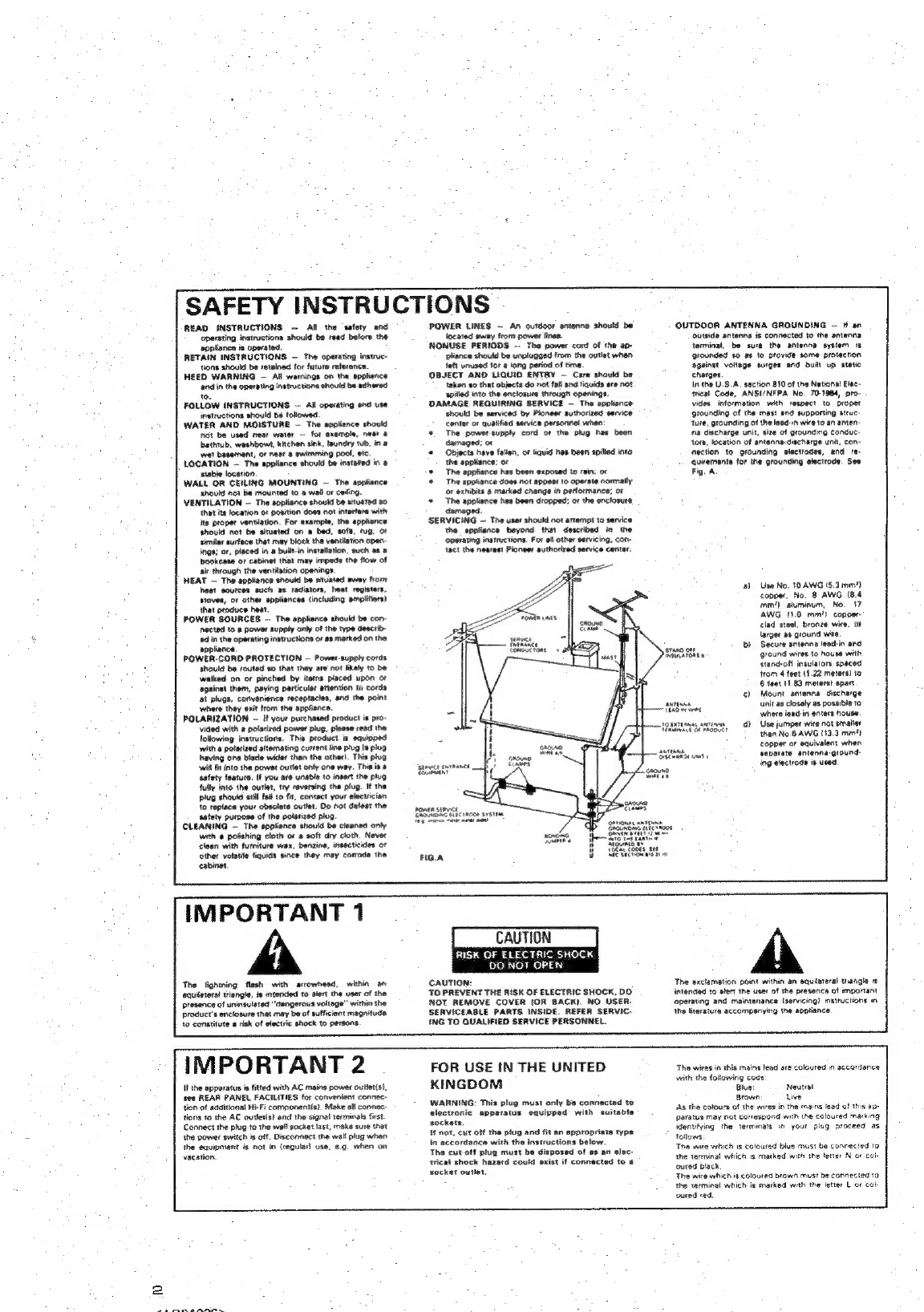
Pioneer TX-1070L User manual

FM/AM
DIGITAL
SYNTHESIZER
TUNER
X=10
70L
X=-10'70
©
These
operating
instructions
are
applicable
to
TX-1070L.
and
TX-1070.
©
The
ifustration
is
for
the
TX-1070L.
However,
the
description
also
applies
to
the
TX-1070.
Operating
Instructions
Thank
you
for
buying
this
Pioneer
product.
Please
read
through
these
operating
instructions
so
you
will
know
how
to
operate
your
model
properly.
After
you
have
fin-
ished
reading
the
instructions,
put
them
away
in
a
safe
place
for
future
reference.
In
some
countries
or
regions,
the
shape
of
the
power
plug
and
power
outlet
may
sometimes
differ
from
that
shown
in
the
explanatory
drawings.
However,
the
method
of
connecting
and
operating
the
unit
is
the
same.
LINE
VOLTAGE
SELECTOR
SWITCH
Only
multi-voltage
models
are
provided
with
this
switch.
U.S.,
Canadian,
European,
U.K.,
and
Australian
models
are
not
provided
with
this
switch.
You
will
find
the
line
voltage
selector
switch
on
the
rear
panel.
Before
your
model
is
shipped
from
the
factroy,
the
switch
is
set
to
the
power
requirements
of
the
destination;
nevertheless,
you
should
check
that
it
is
set
properly
before
WARNING:
To
prevent
FIRE
OR
SHOCK
HAZARD,
DO
NOT
EXPOSE
THIS
APPLIANCE
TO
RAIN
OR
MOISTURE.
IMPORTANT
NOTICE
[For
U.S.
and
Canadian
models]
The
serial
number
for
this
equipment
is
located
on
the
rear
panel,
Please
write
this
serial
number
on
your
enclosed
war-
ranty
card
and
keep
in
a
secure
area.
This
is
for
your
security.
[For
Canadian
model]
CAUTION:
to
prevent
ELECTRIC
SHOCK
DO
NOT
USE
THIS
(POLARIZED)
PLUG WITH
AN
EXTENSION
CORD,
RECEPTACLE
OR
CTHER
OUTLET
UNLESS
THE
BLADES
CAN
BE
FULLY
INSERTED
TO
PREVENT
BLADE
EXPOSURE.
ATTENTION:
pour
prevenin
Les
CHOCS
ELECTRI-
QUES
NE
PAS
UTILISER
CETTE
FICHE
POLARISEE
AVEC
UN
PROLONGATEUR
UNE
PRISE
DE
COURANT
OU
UNE
AUTRE
SORTIE
DE
COURANT,
SAUF
St
LES
LAMES
PEUVENT
ETRE
INSEREES
A
FOND SANS
EN
LAISSER
AUCUNE
PARTIE
A
plugging
the
power
cord
into
the
AC
outlet.
If
the
voltage
is
not
properly
set,
or
if
you
move
to
an
area
where
the
voltage
requirements
differ,
adjust
the
selector
switch
as
follows.
Before
adjusting,
disconnect
the
power
cord,
1.
Use
a
medium-size
screwdriver.
2.
insert
the
screwdriver
into
the
arrow
and
turn
until
it
points
to
the
voltage
value
of
your
area.
Medium
size
screw
driver
CONTENTS
Hints
for
Better
Reception
Troubleshooting
Specifications
0.00...
cee cee
ccc
eee
eee
teense
nese
Connections
...
Front
Panel
Facilities
Automatic
and
Manual
Tuning
.
Presetting
Stations
..

2
READ
INSTRUCTIONS
—
All:
the
‘safety
and
‘operating
instructions
should
be
read
before
the
2ppiiance
is
operated,
RETAIN
INSTRUCTIONS
—
The
operating
instruc-
tions
should
be
retained
for
future
reference.
HEED
WARNING
—
Ail
wamings
on
the
applisnce
‘ond
in
the
operating
instructiona
should
be
adhered
to.
FOLLOW
INSTRUCTIONS
~
All
operating
and
use
instructions
should
be
toliowed.
WATER
AND
MOISTURE
-
The
sppliance
should
Not
be
used
neat
water
—
for
example,
near
e
bathtub,
washbow,,
kitchen
sink,
taundry
tub,
in
@
wet
basement,
or
neat
8
swimming
pool,
etc,
LOCATION
-
The
appliance
should
be
instatted
in»
stable
location,
WALL
OR
CEILING
MOUNTING
—
The
appliance
should
not
be
mounted
to a
wall
or
ceifing.
VENTILATION
~
The
appliance
should
be
situated
so
that
its
focation
of
position
does
not
interfere
with
its
proper
ventilation,
For
example,
the
appliance
thould
not
be
situsted
on
a
bed,
sofa,
rug,
oF
similar
surtece
that
may
block
the
ventitation
open-
ings;
of,
placed
in
#
built-in
installation,
such
ax
a
bookcase
or
cabinet
that
may
impede
the
flow
of
air
through
the
ventitation
openings.
HEAT
—
The
appliance
should
be
situated
away
from
boat
sources
such
as
radiators,
heat
registers,
stoves,
of
other
appliances
{including
amplifiers}
that
produce
heat
POWER
SOURCES
--
The
appliance
should
be
con:
nected
to
a
power
supply
only
of
the
type
describ-
ed
in
the
operating
instructions
or
#8
marked
on
the
appliance
POWER-CORD
PROTECTION
—
Power-supply
cords,
should
be
routed
s0
that
they
are
not
likely
to
be
walked
on
or
pinched
by
items
placed
upon
or
against
them,
paying
particular
attention
to
cords
at
plugs,
convenience
receptacles,
and
the
point
where
they
exit
trom
the
appliance.
POLARIZATION
~
If
your
purchased
product
is
pro-
vided
with
a
polarized
power
plug,
please
read
the
following
instructions.
This
product
is
equipped
with
9
polarized
alternating
current
line
plug
{a
plug
having
one
blade
wider
than
the
other).
This
plug
‘will
it
into
the
powet
outtet
only
one
way.
This
is.
safety
feature.
If
you
ars
unable
to
insert
the
plug
fully
into
the
outlet,
try
reversing
the
pug.
If
the
plug
should
still
fai
to
fit,
contact
your
electrician
fo
replace
your
obsolete
outlet.
Oo
not
defeat
the
satiety
purpose
of
the
polarized
plug
CLEANING
—
The
appliance
should
be
cleaned
only
with
a
polishing
cloth
of
a
soft
dry
clath,
Never
clean
with
furniture
wax,
benzine,
insecticides
of
other
volatile
fiquids
since
they
may
comode
the
cabinet
IMPORTANT
1
The
lightning
flash
with
arrowhead,
within
an
equilateral
triangle,
is
intended
to
alert
the
user
of
the
presence
of
uninsulated
"dangerous
voltage”
within
the
product's
enclosure
that
may
be
of
sutficient
magnitude
to
constitute
a
risk
of
electric
shock
to
persons.
SAFETY
INSTRUCTIONS
POWER
LINES
—
An
outdoor
antenna
should
be
focatad
away
from
power
fines.
NONUSE
PERIODS
—
The
power
cord
of
the
ap-
plance
should
bs
unplugged
from
the
outlet
when
feft
unused
for
a
tong
period
of
time
OBJECT
AND
LIQUID
ENTRY
—
Cars
should
be
taken
20
that
objects
do
not
fall
and
tiquids
sre
not
Spilled
into
the
enclosure
through
openings,
DAMAGE
REQUIRING
SERVICE
—
The
appliance
should
be
serviced
by
Pioneer
authorized
service
center
or
qualified
service
personnel
when:
*
The
power-supply
cord
or
the
plug
has
been
damaged;
ot
©
Objects
have
falten,
of
liquid
has
been
spilled
into
the
appliance;
of
+
The
appliance has
been
exposed
to
rain;
or
*
The
appliance
does
not
appear
to
operate
normally.
or
exhibits
a
marked
change
in
performance;
or
+
The
appliance
has
been
dropped:
of
the
enclosure
damaged.
SERVICING
—
The
user
should
not
attempt
to
service
the
eppliance
beyond
that
described
in
the
operating
instructions,
For
ell
other
servicing,
con-
tact
the
nearest
Pioneer
authorized
service center.
ORR
mS.
senvece
feikince
FIG.A
CAUTION
RISK
OF
ELECTRIC
SHOCK
DO.NOT.
OPEN.
CAUTION:
TO
PREVENT
THE
RISK
OF
ELECTRIC
SHOCK,
DO
NOT
REMOVE
COVER
{OR
BACK).
NO
USER:
SERVICEABLE
PARTS
INSIDE.
REFER
SERVIC-
ING
TO
QUALIFIED
SERVICE
PERSONNEL.
IMPORTANT
2
It
the
apparatus
is
fitted
with
AC
mains
power
outiet(s,
see
REAR
PANEL
FACILITIES
for
convenient
connec:
tian
of
additional
Hi-Fi
componentis}.
Make
alt
connec
tions
to
the
AC
outter{s}
and
the
signat
terminals
first.
Connect
the
plug-to
the
wall
socket
last,
make
sure
that
the
power
switch
is
of.
Disconnect
the
wall
plug
when
the
equipment
is
not
in
(regular
use.
e.g.
when
on
vacation.
FOR
USE
IN
THE
UNITED
KINGDOM
WARNING:
This
plug
must
only
be
connected
to
slectronic
apparatus
equipped
with
suitable
sockets,
4
not,
cut
off
the
piug
and
fit
sn
appropriate
type
in
accordance
with
the
instructions
below.
The
cutotf
plug
must
be
disposed
of
as
an
elec:
trical
shock
hazatd
could
exist
if
connected
to
s
socket
outlet.
STAND
OFF
INSULATORS
8
ANTE
TPAD
on
ene
10.
OTOL
anTiowen
Tinted
OF
PRODUCT
mest,
Bikemaitse
um
OP
NOMAL
ahi,
UNE
EEC
TROOE
Basenasntty
wm
Sgt
rane
siguaro
(hehe
Coors,
see
NEE
SEERA
ee
on
OUTDOOR
ANTENNA
GROUNDING
—
ff
an
outside
antenns
is
connected
to
the
antenna
terminal,
be
sure
the
antenna
system
ix
Grounded
so
at
to
provide
some
protection
against
voltage
surges
and
built
up
static
chargos
Inthe
U.S.A.
section
810
ot
the
National
Elac-
trical
Code,
ANSUNFPA
No,
70-1984,
pro-
vides
information
with
respect
to
propet
grounding
of
the
mast
and
supporting
struc
ture,
grounding
of
the
lead-in
wire
to
an
anten:
na
discharge
unit,
sita
of
grounding
conduc:
tors,
location
of
antenna-discharge
unit,
con-
nection
to
grounding
electrodes,
and
re-
quirements
for
the
grounding
electrode.
See
Fig.
A
2)
Use
No.
10
AWG
(5.3
min}
copper,
No.
8
AWG
(8.4
mm?)
aluminum,
No.
17
AWG
(1.0
mm")
copper:
clad
steel,
bronze
wire,
ot
larger
as
ground
wir
b)
Secure
antenna
lead-in
and
ground
wires
to
house
with
stand-off
insulators
spaced
trom
4
feet
(1.22
meters)
to
6
feet
11.83
meters!
apart
¢)
Mount
antenna
discharge
unit
as
closely
as
possible
to
where
lead-in
enters
house.
3)
Use
jumper
wite
not
smalier
than
No.6
AWG
(13.3
mmm!)
copper
of
equivalent
when
separate
antenna.ground:
ing
electrode
is
used,
The
exclamation
point
within
an
equiateral
tangle
rs
intend
to
atert
the
user
of
the
presence
of
important
operating
and
maintenance
(servicing?
mstructions
im
the
fterature
accompanying
the
appliance.
The
wires
in
this
mains
lead
are
colovted
in
accordance
with
the
following
code
Blue
Neutral
Brown:
ke:
As
the
colours
of
the
wires
in
the
mains
lead
of
this
ap-
paratus
may
not
correspond
with
the
coloured
marking
identitying
the
terminals
in
your
plug
proceed
as
follows
The
wire
which
is
coloured
blue
must
be
connected
t0
the
terminal
which
is
marked
with
the
lerter
N
ot
cok
oured
black
The
wire
which
is
coloured
brown
must
be
connected
to
the
terminal
which
is
marked
with
the
letter
L
of
cob
oured
red.

CONNECTIONS
*
Use
for
FM
reception
un-
AM
LOOP
ANTENNA
Ue
speci
nurore
FM
|
Ascawony
FM,”
Quidoer
FM
|
“e
‘Unfold
all
four
lage
of
the
AM
loop
©
Stretch
both
ends
taut
,
antenna
toward
the
outside,
and
insert
and
affix
to
a
wall,
etc.
the
stopper
inside
the
legs
into
the
hole
in
the
AM
loop
antenna
to
fix
it
in
position.
¢
Set
the
antenna
on
a
level
surface,
and
point
in
the
direction
that
gives
op-
timum
reception.
@
Do
not
install
the
antenna
in
locations
where
it
touches
the
cover
of
the
tuner
or
other
metal
objects,
or
near
a
CD
player,
personal
computer,
or
televi-
sion
set.
Stretch
taut
and
affix.
Only
TX-1070L
is
equipped
with
PAL
socket.
Refer
to
“HINTS
FOR
BETTER
RECEPTION"
in
the
page
9:
Accessory
AM
Loop
Antenna
CONNECTING
THE
FM
T-TYPE
ANTENNA
and
THE
AM
LOOP
ANTENNA
iy
Wrap
the
ends
of
the
wire
in
a
clockwise
direction
around
the
base
of
the
terminals
and
tigh-
ten
the
terminals
to
secure
It.
Antenna
ground
Although
grounding
is
not
necessary
for
reception,
it
is
recommended
for
protection
against
damage
from
lightning
if
an
outdoor
FM
antenna
is
used.
Grounding
is
recommend-
ed
as
weil
to
help
reduce
noise
and
hum.
NOTE:
Never
make
the
ground
connection
to
a
gas
pipe
as
sparks
could
cause
the
gas
to
ignite.
Pin
plug
connecting
cord
*
Connect
the
white
plug
to
the
white
terminal
(L)
and
the
red
plug
to
the
red
terminal
(R).
e
Make
sure
that
there
is
a
proper
connection.
Connecting
the
power
cord
Plug
the
power
cord
into
(SWITCHED)
the
auxiliary
power
outlet
on
the
amp~
lifier
or
into
an
AC
wall
socket.
CHANNEL
STEP/DE-EMPHASIS
switch
{Applicable
to
multi-voltage
models
only}
This
switch
has
been
set
before
shipping
to
the
channel
allocation
and
de-emphasis
value
for
the
area
in
which
the
unitis
sold.
If
the
switch
is
set
incorrectly,
the
reception
frequency
display
will
not
stop,
and
even
if
reception
is
possible,
it
may
sound
unnatural.
In
order
to
prevent
such
occurences,
be
sure
to
check
that
the
switch
is
set
property
before
using
the
unit.
(100/10.kHz}/75
ps.
..
North
America
and
(50/9
KHz}/50
[8
oes
ceceeesceeeeeeeseeeneressneneteeenensess
R
Stereo
amplifier
CHECKING
OUT
THE
ACCESSORIES
AM
loop
Antenne
FM
Ttype
antenna
Connection
cord
a
1
with
pin
plug..
<ARB1026>.

FRONT
PANEL
FACILITIES
EET.
PUNE
TION
FM
@illiip
AM
@
POWER
switch
When
this
switch
is
set
to
the
on
position,
power
is
supplied
to
the
tuner’s
main
circuits.
The
unit's
POWER
switch
is
geared
to
selecting
the
transformer’s
secondary
and
so
even
at
the
STAND-
BY
position,
the
unit's
circuitry
will
work
as
long
as
the
power
cord
is
connected
to
a
power
outlet.
Disconnect
the
power
cord
from
the
power
outlet
when
you
do
not
plan
to
use
the
unit
for
a
long
period
of
time.
@
FM
STEREO
indicator
This
lights
when
a
stereo
program
has
been
picked
up
during
an
FM
broadcast
reception.
©
TUNED
indicator
This
lights
up
to
indicate
when
the
finest
tuning
of
a
station
has
been
achieved.
@
FREQUENCY/CHANNEL
display
This
shows
the
frequency
of
the
station
currently
be-
ing
received
in
digital
form.
The
FM
band
is
indicated
by
MHz,
and
the
AM
(LW,
MW)
band
by
kHz.
The
channel
number
of
the
STATION
CALL
switch
is
displayed
also,
cat
a
Sa
patie
@
MEMORY
indicator
@
FM
MONO
switch/indicator
Normally,
when
receiving
an
FM
stereo
broadcast,
leave
this
switch
OFF.
If
the
broadcast
station
is
dis-
tant,
or
if
you
are
in
a
poor
reception
area,
the
input
signals
will
be
weak,
and
during
stereo
reception,
noise
will
be
prominent,
making
the
broadcast
dif-
ficult
to
hear.
In
such
a
case,
press
ON
this
switch.
The
broadcast
will
be
reproduced
in
monaural,
however
noise
will
be
reduced,
enabling
the
broad-
cast
to
be
heard
more
clearly.
NOTE;
*
This
switch
does
not
function
when
you
are
listening
to
an
AM
broadcast.
*
The
ON
or
OFF
status
of
the
FM
MONO
switch
will
be.
memorized
when
you
preset
a
station
in
the
STATION
CALL
switch.
By
using
the
RECEPTION
USING
PRESET
CALL
function,
you
can
receive
an
FM
broadcast
at
any
time
in
the
same
mode.

FRONT
PANEL
FACILITES
@
MEMORY
switch
This
is
used
to
memorize
stations.
When
the
switch
is
depressed,
the
MEMORY
indicator
will
light.
To
memorize
the
frequency
of
any
station,
press
the
STATION
CALL.
switch
while
the
MEMORY
in-
dicator
is
lighting
up.
@
TUNING
switches
(~,
+ )
,
These
are
used
to
locate
stations.
Push
the
left
half
of
this
switch
’—"’
to
locate
a
station
broadcasting
on
a
lower
frequency
and
the
right
half
of
this
switch
“4.
to
locate
a
station
broadcasting
on
a
higher
fre-
quency.
@
MANUAL/AUTO
selector/indicator
Use
this
switch
in
combination
with
the
FREQUEN-
CY/CHANNEL
selector
when
changing
the
tuning
methods:
¢
AUTO
SEARCH
TUNING,
*
MANUAL
TUNING,
*
AUTO
INDEX
CHANNEL
SCAN,
*
MANUAL
INDEX
CHANNEL
SCAN.
When
this
selector
is
pressed
so
that
the
AUTO
in-
dicator
lights,
the
AUTO
mode
will
be
activated.
For
details,
see
pages
6,7
and
8.
®
FREQUENCY/CHANNEL
selector/indicator
Use
this
selector
together
with
the
MANUAL/AUTO
selector
of
@
when
changing
the
tuning
method.
When
it
is
pressed
so
that
the
CHANNEL
indicator
lights,
the
CHANNEL
mode
will
be
activated.
For
details,
see
pages
6,7
and
8.
@
FUNCTION
switches
These
are
used
to
select
either
the
FM,
MW
or
LW
broadcasting.
bands.
FM:
Push
to
receive
FM
band
broadcasts.
MW:
Push
to
receive
MW
band
broadcasts.
LW:
Push
to
receive
LW
band
broadcasts.
Only
AM/FM
switching
is
availabe
model
for
the
TX-1070.
@
STATION
CALL
switches
These
are
used
to
preset
and
recall
broadcasting
sta-
tions.
@
Station
mode
SELECT
‘switch/indicator
Use
this
switch
to
set
the
station
call
switches
to
either
the
No.
1
mode
(1
—
8),
or
the
No.
2(9
—
16),
When
the
switch
is
pressed
so
that
the
indicator
lights,
the
No.
2
mode
(9
—
16)
has
been
selected.
NOTE:
Merely
setting
this
switch
will
cause
no
change
in
tuner
operation.
ko)
<ARB1026>

AUTOMATIC
AND
MANUAL
TUNING
e
Check
that
all
terminals
are
properly
connected
before
switching
on
the
unit.
®
Before
starting
to
use
the
unit,
turn
the
FUNCTION
switches
on
the
stereo
amplifier
to
TUNER.
LAUTO
SEARCH
TUNING
|
The
electronic
tuning
circuit
inside
the
unit
will
search
for
your
desired
station
automatically,
3
—
TUNING
Preivanre.
CA]
4
This
tuning
method
is
used
in
the
following
cases:
«
When
presetting
each
frequency
corresponding
to
the
desired
station
using
the
STATION
CALL
switch.
(For
details
on
the
presetting,
see
page
6.)
*
When
tuning
in
to
a
station
irrespective
of
the
preset
stations
reception
area,
perform
tuning
manually
using
the
following
procedure.
1
Turn
on
the
POWER
of
the
unit
and
the
stereo
amplifier.
2
Select
your
desired
broadcasting
band
using
the
FUNCTION
switch-
es.
3
Press
the
MANUAL/AUTO
selector
so
that
the
AUTO
indicator
lights.
4
Press
the
FREQUENCY/CHANNEL
selector
so
that
the
CHANNEL
in-
dicator
goes
out.
5
Press
the
“+”
or
’-""
TUNING
switch,
By
simply
pressing
the
tuning
switch,
the
tuner
will
automatically
search
for
a
station
and
tune
in
to
it.
By
pressing
“+,
the
frequency
will
move
upwards,
and
by
pressing
‘’~’’,
the
frequency
will
move
downwards.
Each
time
the
switch
is
pressed,
the
next
higher
{or
lower}
frequency
station
will
be
tuned
in.
NOTE:
When
AUTO
SEARCH
is in
use,
reception
may
not
be
possible
over
long
distances
or
when
signals
are
weak.
At
these
times
manual
tuning
is
recommended.
6
<ARB1026>
Caution
with
Auto-Searc
¢
Since
this
is
a
highly
sensitive
mechanism,
the
fre-
quency
Auto-Search
operation
may
stop
even
with
weak
foreign
broadcasts,
particularly
at
night,
Also
frequency
noise
in
large
cities
may
cause
the
seach
operation
to
stop,
@
When
using
Auto-Search
to
preset
AM
stations,
if
the
frequency
search
operation
stops
too
frequently,
changing
the
position
of
the
AM
loop
antenna
may
be
of
help
in
reducing
its
sensitivity
so
that
only
power-
ful,
nearby
stations
are
received.
After
tuning
in
the
station,
be
sure
to
reposition
the
antenna
to
its
best
position
for
reception.
*
For
very
weak
stations,
use
the
manual!
tuning
mode
to
preset
stations,
3
TUNING
ee
oe
se
aore,
Ce
PETIT
—
me
csaAnird
4
4
3
5
1
Turn
on
the
POWER
of
the
unit
and
the
stereo
amplifier.
2
Select
your
desired
broadcasting
band
using
the
FUNCTION
switch-
es.
3.
Press
the
MANUAL/AUTO
selector
so
that
the
AUTO
indicator
goes
out.
4
Press
the
FREQUENCY/CHANNEL
selector
so
that
the
CHANNEL
in-
dicator
goes
out.
5
Use
the
TUNING
switches
“~”
or
“+”
to
locate
the
frequency
of
your
desired
station.
For
step-by-step
searching,
press
the
TUNING
switch
once
and
release
it
immediately.
For
continuous
rapid
scanning
keep
the
TUNING
switch
pressed,
The
TUN-
ED
indicator
will
light
up
when
the
desired
station
is
tuned
in
best.
NOTE:
The
TUNED
indicator
will
not
function
for
broadcasts
received
over
long
distances
or
when
signals
are
weak.

PRESETTING
STATIONS
[PRESETTING
_
|
_=
=”
4
2
TUNING
+
3
1
Turn
on
power
to
this
unit
and
the
stereo
amplifier.
2.
Select
the
broadcasting
band
to
be
memorized,
using
the
FUNCTION
switch.
3
Tune
in
the
desired
station.
©
See
the
AUTO
SEARCH
TUNING
section
for
infor-
mation
on
reception
using
auto-search
tuning.
*
See
the
MANUAL
TUNING
section
for
information
on
reception
using
manual
tuning
.
4
After
tuning
in
to
an
FM
broadcast,
set
the
FM
MONO
switch
to
the
position
which
provides
best
overall
listening
conditions.
*
You
can
also
preset
the
ON
or
OFF
status
of
the
FM
MONO
switch
in
the
STATION
CALL
switch.
This
enables
you
to
receive
the
same
broadcast
at
any
time
in
the
same
mode.
5
Press
the
station
mode
SELECT
switch
to
select
Mode
1
or
Mode
2.
When
presetting
using
Mode
1
STATION
CALL
switches
Goes
out.
seceer
ul
—
$16
When
presetting
using
Mode
2
STATION
CALL
switches
Lights
sriecr
ape 913
6a
75
e/a
8-76
So8,
S08,
Ss,
2
1
Press
OOOO
HOO
Press
the
MEMORY
switch.
©
The
memory
indicator
lights.
7
Press
the
STATION
CALL
switch
in-
to
which
you
wish
to
preset
the
sta-
tion.
e
Perform
presetting
during
the
time
that
the
MEMORY
indicator
lights.
elf
the
MEMORY
indicator
goes
out,
presetting
is
no
longer
possible,
Press
the
MEMORY
switch
again
to
perform
presetting.
oO
8
Repeat
steps
2
to
6
to
preset
stations
into
STATION
CALL
switches
1
through
16.
A
total
of
up
to
16
stations
{including
FM,
LW
and
MW)
can
be
preset.
If
a
new
station
is
memorized
in
a
preset
switch
already
containing
a
memorized
station,
the
previously
memorized
station
data
will
be
erased,
and
the
last-memorized
station
will
be
entered
in
the
switch.
PRESET
STATION
VERIFICATION
|
ee
TUNING
eee
1
2
SELECT
Nae
A
SSooOUoOULIL
O
1
Press
the
FREQUENCY/CHANNEL
and
MANUAL/AUTO
selectors
so
that
the
both
indicators
light.
2
Press
the
“+”
or
“~”
TUNING
switch.
The
receiver
will
search
for
the
frequency
of
each
sta-
_
tion
which
was
preset
by
the
STATION
CALL
switch.
Each
station
will
be
tuned
in
successively,
and
the
channel
number
and
frequency
(MHz
or
kHz)
will
be
displayed
for
about
5
seconds.
Observe
this
display
to
check
whether
or
not
the
desired
preset
station
has
been
tuned
in.
Press
the
STATION
CALL
switch
corresponding
to
the
previously
preset
station.
(When
necessary,
do
not
neglect
to
perform
SELECT
selection
as
well.)
>
<ARB1026>

PRESETTING
STATIONS
AUTO
INDEX
CHANNEL
SCAN
|
You
can
find
out
which
programs
are
being
broadcast
on
each
of
the
preset
stations
using
the
PRESET
STA-
TION
VERIFICATION
procedure
described
above.
As
each
preset
station
is
tuned
in,
press
the
STATION
CALL
switch
to
listen
to
the
broadcast.
SELECT
MEMORY
B14
775
BF6
Cobo
Ci
1
Turn
on
power
to
this
unit
and
to
the
stereo
amplifier.
2
Press
the
FREQUENCY/CHANNEL
and
MANUAL/AUTO
selectors
so
that
the
both
indicators
light.
3
Press
the
“+
or
“~”
TUNING
switch.
When
“+”
is
pressed,
the
stations
will
appear
in
the
sequence:
goes
out
pie
lights
When
”~"'
is
pressed,
the
stations
will
appear
in
the
sequence:
sevect
sar*
goes
out
4,
Press
the
STATION
CALL
switches
corresponding
to
the
previously
preset
station
that
you
wish
to
hear.
By
following
these
procedures,
tuning
may
be
ef-
fected
simply
and
accurately.
=
YvAORING.~,
Use
the
following
procedure
to
manually
tune
in
each
preset
station
in
sequence.
2
coe
FLING
er
oof
Eaeeatien
a
3
4
1
Turn
POWER
to
this
unit
and
to
the
stereo
amplifier.
2
Press
the
MANUAL/AUTO
selector
so
that
the
AUTO
indicator
goes
out.
3.
Press
the
FREQUENCY/CHANNEL
selector
so
that
the
CHANNEL
in-
dicator
lights.
4
Press
the
“+”
or
“~-"
TUNING
switch.
Last
station
memory
*
When
the
POWER
switch
is
pressed
to
turn
power
on,
the
last
station
received
before
the
power
was
previously
turned
off
will
be
received
again.
*°
When
power
is
ON,
if
the
FUNCTION
switches
are
pressed,
the
last
station
received
before
the
FUNC-
TION
switches
were
previously
pressed
will
be
received
again.
NOTE:
@
Preset
stations
will
be
retained
in
the
memory
when
the
POWER
is
switched
to
STAND-BY
as
long
as
the
power
cord
is
not
disconnected.
e
/t
is
recommended
that
you
disconnect
the
power
cord
when
the
unit
is
not
being
used
for
long
periods
of
time,
The
electrical
circuit
controlling
the
MEMORY
furiction
is
powered
by
a
back-up
condenser
so
that
the
unit
will
retain
preset
stations
for
a
few
weeks.
®
if
a
preset
station
has
been
erased,
reset
it.

HINTS
FOR
BETTER
RECEPTION
INDOOR
VS.
OUTDOOR
ANTENNAS
lf
FM
reception
is
poor
when
using
the
accessory
T-type
antenna,
it
means
that
you
are
not
living
in
@
good
reception
area.
In
this
case,
setting
up
a
good
outdoor
FM
antenna
will
solve
this
problem
NOTE
oe
j
Consult
your
dealer
as
to
the
selection
and
actuaf
instalfa-
|
tion
of
the
FM
antenna.
|
FM
ANTENNA
CONNECTIONS
There
are
two
ways
of
connecting
the
FM
antenna
to
the
antenna
input
terminals:
with
a
300-ohm
twin-lead
feeder
or
with
a
75-ohm
coaxial
cable.
If
full
justice
is
to
be
done
to
the
tuner’s
performance,
a
75-ohm
coax-
ial
cable
is
recommended
since
it
is
more
immune
than
the
twin-lead
feeder
to
noise
and
interference
from
ex-
ternal
sources.
tf
an
FM
antenna
has
already
been
erected
outdoors,
connect
it,
referring
to
the
figure.
GROUNDING
Grounding
is
recommended
if
reception
of
FM
pro-
grams
is
impaired
by
noise.
To
ground,
connect
a
thick
polyvinyl!
insulated
wire
to
the
GND
terminal
and
attach
the
other
end
to
a
metal
water
pipe
or
grounding
bar
or
wind
it
around
a
copper
plate
and
bury
it.
NOTE:
enn
en
ennnencn
nnn
ni
nee
age
Never
connect
a
wire
to
a
gas
pipe
tor
grounding
since
|
Sparks
may
ignite
the
gas
Lect
satiate
OUTDOOR
AM
ANTENNAS
The
accessory
AM
loap
antenna
is
quite
sufficient
if
you
live
in
a
strong-signal
area.
However,
an
outdoor
AM
antenna
should
be
erected
if
surrounding
objects
are
interfering
with
reception
or
if
the
stations
are
dis-
tant
and
their
signals
are
weak.
NOTE,
one
Do
not
detach
the
AM
loap
antenna
when
using
an
outdoor
AM
antenna.
[Connecting
the
coaxial
cable
Only
TX-1070
is
not
equipped
with
PAL
socket.
FM
antenna
Core
(+4
Shield
(~)
Unit:
mm
75-ohm
coaxial
cable
without
75
&
coaxial
|
PAL
connector
cable
75-ohm_
coaxial
cable
with
PAL
connector
~~
_
[Cone
J
FM
antenna
Twist
the
strands
togeter.
p~"
—
ie
pind
y
i
|
|
eae
~
a
Ls
rh
ane
{
PolleeAred
Unit:
mm
a
as
3002
feeder
:
Ground
3002
terminals
-
Ground
terminal
AM
wire
anten
(Polyvinyl
in
sulated
wire)
c=
-APBRINDIRD

TROUBLESHOOTING
If
you
think
your
unit
is
malfunctioning,
take
the
time
to
check
out
the
points
below.
In
many
cases,
carelessness
or
incorrect
operation
is
to
blame.
Alternatively,
the
problem
may
lie
outside
the
unit.
Make
a
point
of
checking
the
other
stereo
components
being
used
as
well
as
any
other
electrical
appliances.
{f
the
trouble
is
not
remedied
even
after
checking
the
points
below,
contact
your
nearest
authorized
Pioneer
service
station.
Symptom
No
power
No
sound
Static
|
Sound
distortion
[On
the
FM
band]
Sound
distortion
{On
the
AM
band]
Stereo
broadcasts
not
received
in
stereo.
Couse
Has
the
power
cord
been
disconnected?
or
incorrectly
connected?
Has
the
antenna
been
disconnected
or
is
the
connection
loose?
tuner?
Are
the
signals
weak
and
reception
poor?
Has
the
power
switch
been
left
off
for
several
days?
(Station
memory
has
been
lost.)
Is
the
station
properly
tuned
in
to
the
correct
frequency?
Has
the
antenna
been
disconnected
or
is
the
connection
loose?
Have
any
of
the
output
cords
been
disconnected
*
Reconnect
the
power
cord
*
Connect
them
properly
to
the
TUNER
terminals
on
the
amplifier.
Connect
the
antenna
propery,
Reprogram
station
memory.
*
Tune
in
the
station
correctly,
Connect
the
antenna
properly,
Is
the
FM
T-type
antenna
still
folded
up
and
not
extended
or
is
the
antenna
facing
in
the
wrong
direction?
Static
from
other
appliances
{particularly
automobiles)
or
multipath
reflection
(radio
waves
beamed
off
mountains
and
tall
buildings
and
not
received
directly.)
Poor
positioning
of
AM
loop
antenna?
is
accessory
AM
loop
antenna
in
contact
with
Are
the
signals
weak
and
reception
poor?
lights
/motors?)
lent
input?
Are
the
signals.
weak,
with
insu
is
the
frequency
tuned
in
properly?
Static
from
other
electrical
appliances
{fluorescent
|
|
;.®
Tune
in
station
accurately.
Extend
the
two
ends
of
the
antenna
and/or
change
the
direction
of
the
antenna
until
best
reception
is
ob-
tained.
Substitute
an
FM
outdoor
antenna
for
the
FM
T-type
antenna
Try
varying
the
height
and
direction
of
the
antenna
or
use
an
FM
outdoor
antenna
substituting
a
75-ohm
coax-
ial
cable
for
the
standard
cable
and
‘i
fixing
it
as
far
away
as
possible
from
the
street
Change
the
direction
of
the
antenna
until
best
reception
is
obtained.
Separate
the
AM
toap
antenna
as
far
as
possible
from
tuner.
*
Fix
an
AM
outdoor
antenna
or
ground
the
antenna.
Switch
off
other
appliances
or
keep
as
far
away
as
possible
from
the
|
tuner
when
in
use.
e
Change
to
an
outdoor
FM
antenna
is
the
FM
MONO
switch
ON?
Press
the FM.
MONO
switch
OFF.
410
YARRINGBAY~

SPECIFICATIONS
(Model
TX-1070L)
FM
Tuner
Section
Frequency
range
..
Usable
Sensitivity
.
50
dB
Quieting
Sensitivity
.............:.:eeeeneeseneeeeeeeees
Stereo;
36.2
dBf,
IHF
(17.8
2V/75
2)
Sensitivity
(DIN)
..........
02
seer
eee
Mono;
0.9
pV/75
2
Stereo;
30
pV/75
$2
Signal-to-Noise
Ratio
..........
Mono;
78
dB
(at
80
dBf)
Stereo;
76
dB
(at
80
dBf)
Signal-to
Noise
Ratio
(DIN)
................
Mono;
66
dB
Stereo;
60
dB
Distortion
(at
80
dBf)
.............
Stereo;
0.35%
(1
kHz)
Alternate
Channel
Selectivity
67
dB
(400
kHz}
Stereo
Separation
........-.cceeeeeesee
renee
40
dB
(1
kHz)
Frequency
Response
$3
dB
(30
Hz
to
15
kHz)
50
dB
Image
Response
Ratio
.
IF
Response
Ratio
...
:
AM
Suppression
Ratio
...........0:eseeeeeeeereeeeeees
50
dB
Antenna
Input
...
.
300
2
balanced
75
2
unbalanced
MW
Tuner
Section
Frequency
fange
.........cceeeee
531
kHz
to
1,602
kHz
Sensitivity
(IHF,
Loop
antenna)
--
400
pV
/m
Selectivity
...........
ie
Signal-to-Noise
Ratio
Image
Response
Ratio
.
IF
Response
Ratio
.
Antenna
LW
Tuner
Section
Frequency
range
.
Selectivity
.........
Signal-to-Noise
Ratio
Image
Response
Ratio
Antenna
153
kHz
to
281
kHz
22
dB
.
52
dB
40
dB
.,
Loop
Antenna
Audio
Section
Output
(Level/Impedance)
FM
(100%
MOD)
FIXED
..........4...
650
mV/3,6
k2
MW//LW
(30%
MOD)
FIXED
..
150
mV/3.6
k&
Miscellaneous
Power
Requirements
........
a.c.
220
Volts,
50/60
Hz
Power
Consumption
95W
Dimensions
............-.5
420
(W)
x
60
(H)
x
219
(D)
mm
Weight
(without
package)
..............
2.4
kg
(5
lb
§
oz)
Furnished
Parts
FM
T-type
Antenna
...
AM
Loop
Antenna
..
Connection
Cord
with
Pin
Plugs
.
Operating
Instructions
NOTE:
Specifications
and
design
subject
to
possible
modification
without
notice
due
to
improvements.

SPECIFICATIONS
(Model
TX-1070)
FM
Tuner
Section
Frequency
Fange
.......eeceeeeeee
87.5
MHz
to
108
MHz
Usable
Sensitivity
........-.
11.2
dBf,
IHF
(1.0
nV/75
Q)
50
dB
Quieting
Sensitivity
............0.-
Cases
Stereo;
36.2
dBf,
(HF
(17.8
1V/75
82)
Sensitivity
(DIN)
.........esereeereeees
Mono;
0.9
pV/75
$2
Stereo;
30
pV/75
2
Signal-to-Noise
Ratio
..........
Mono;
78
dB
{at
80
dBf)
Stereo;
76
dB
(at
80
dBf)
Signal-to
Noise
Ratio
(DIN)
.........-...25
Mono;
66
dB
Stereo;
60
dB
Distortion
(at
80
dBf)
..........
...
Stereo;
0.35%
(1
kHz)
67
dB
(400
kHz)
...
40
dB
(1
kHz)
*2
3.
dB
(30
Hz
to
15
kHz}
...
50
dB
110
dB
Alternate
Channel
Selectivity
Stereo
Separation
.....
Frequency
Response
-
Image
Response
Ratio
.
IF
Response
Ratio
....
AM
Suppression
Ratio
.
Antenna
Input
.
300
2
balanced
75
8
unbalanced
AM
Tuner
Section
Frequency
range
......2............
531
KHz
to
1,602
kHz
Sensitivity
(HF,
Loop
antenna)
...............
400
pV/m
Selectivity
Signal-to-Noise
Ratio
Image
Response
Ratio
....
{F
Response
Ratio
..........
ANteNnad
oo...
0.
cece
rene teen
52
dB
».-
40dB
...
50
dB
...
Loop
Antenna
Station
Call
Switch
Memo
Audio
Section
Output
Level
FM
(100%
MOD)
...
AM
(30%
MOD)
....
..
650
mV/3.6
ke
w+.
150
mV/3,6
k&2
Miscellaneous
Power
Requirements
.
a.c.
220
Volts~,
50/60
Hz
Power
CoOnSumption
......cec:ececrsccerr
eer ner
er
euee
95W
Dimensions
......
..
420
(W)
x
60
(H)
x
219
(D)
mm
Weight
(without
package)
...........65
2.4
kg
(5
lb
5
oz)
Furnished
Parts
FM
T-type
Antenna
AM
Loop
Antenna
..
Connection
Cord
with
Pin
Plugs
.
Operating
Instructions
.........6-5
ae
eeraneranery
NOTE:
Specifications
and
design
subject
to
possible
modification
without
notice
due
to
improvements.
Use
the
form
below
to
record
the
preset
stations
and
their
frequency
as
a
reference.
/
cho
3
4
5
6
7
8
|
ation
Call
Letters
|
“Broadcast
Frequency
|
i”
|
S
S.C.
Switch
:
|
0
"|
«12
Ee
ee
46.
4
|
__
Station
Call
Letters
i
|
i
i
|
i
!
t
=
Bey
7
Broadcast
Frequency
ia
PIONEER
ELECTRONIC
CORPORATION
4-1,
Meguro
1-Chome,
Meguro-ku,
Tokyo
1S,
vanan
PIONEER
ELECTRONICS
[USA]
ING.
SOOO
Arport
Plaza Drive
P.O.
Box
1720.
Long
Beach.
Catfornia
90801-1720
U.S.A.
PIONEER
ELECTRONIC
[EUROPE]
N.V.
Keetbergisan
1,
2740
Beveren,
Geigur
TEL:
03/7752808
PIONEER
ELECTRONICS
AUSTRALIA
PTY.LTD.
175-184
Boundary
Sead,
Braeside,
Victoria
3195,
Austrera
TEL:
[03]
SBO-3911
<86KOOFSD05>
Printed
in
Japan
<AR81026-A>
This manual suits for next models
1
Other Pioneer Tuner manuals

Pioneer
Pioneer DEH-2330R User manual

Pioneer
Pioneer TX-5300 User manual

Pioneer
Pioneer GEX-P900DAB User manual

Pioneer
Pioneer ND-MDT10 User manual

Pioneer
Pioneer TX-1080Z User manual

Pioneer
Pioneer TX-D1000 User manual

Pioneer
Pioneer F-551L User manual

Pioneer
Pioneer F-91 User manual

Pioneer
Pioneer TX-930 User manual

Pioneer
Pioneer TS7 User manual

Pioneer
Pioneer KEX-70 User manual

Pioneer
Pioneer F-99X User manual

Pioneer
Pioneer ND-TMC10 User manual

Pioneer
Pioneer F-402 User manual

Pioneer
Pioneer GEX-P910XM User manual

Pioneer
Pioneer XC-IS21MD User manual

Pioneer
Pioneer F-443L User manual

Pioneer
Pioneer TX-600 User manual

Pioneer
Pioneer F-225L User manual

Pioneer
Pioneer GEX-P700DAB/EW User manual