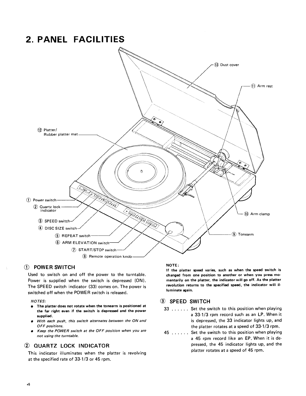
Pioneer PL-L1000 User manual

FS
Eefticec%anual
LINEARMOTORARM STEREO
TURNTABLE
PL-L1cI0(f
()rrrorueEr{

Type Voltage Remarks
HET 22OV and 240V (Switchablel Europe model (without cartridge)
HBT 22OY and 24OV (Switchablel United Kingdom model (without cartridgel
s/G 1lOV.12OV,
22OV,24OVand
(Switchablel U.S. Military model (with cartridge)
MODEL
PL-LIOOO
COMES
IN THREEVERSIONS
DISTINGUISHED
AS FOLLOWS:
CONTENTS
t
1. SPECIFICATIONS
2. PANEL
FACILITIES
3. DISASSEMBLY
3.1 Panel
.
3.2 D.D.Motor
3.3 Tonearm
3.4 CdSDetector
andLamp
4. PARTSLOCATIONS
5. BLOCKDIAGRAM
5.1 Tonearm
Control
Stage
.
5.2 EndDetector
Stage
.
5.3 Arm Elevation
Control
Stage
5.4 SizeSelectorStage .
5.5 RepeatControlStage
5.6 Lowering
Position
Detector,
Plunger
ControlStage
andDescent
Signal
Generator
5.7 Display
Stage
and
Plunger
Driver.
5.8 Manual
Drive
Stage
5.9 Tracking
Sensor
Stage
and
TonearmDriver
Stage
5.10 D.D.
MotorControl
Stage
and
D.D.Motor
Stop
Control
6. CIRCUITDESCRIPTIONS
6.1 Full
AutoLogic.
6.2 TonearmDrive
.
7. ADJUSTMENTS
7.1 D.D.
MotorOperating
Point
Adjustment
7.2 Auto Lead-inTimingAdjustment
7.3 End
SensorSensitivity
Adjustment
7.4 End
Timer
Adjustment
7.5 Tracking
Sensor
Zero
Point
Adjustment
7.6 Tracking
Sensor
GainAdjustment . . . . .
7.7 Lead-in
and
Return
Speed
Adjustment. . .
8. TIMING
CHART
9. TROUBLESHOOTING
9.1 CircuitBlock.
9.2 MechanismBlock .
10.EXPLODED
VIEWS
10.1 Exterior
10.2 Tonearm
10.3 EV
Mechanism
10.4 Bottom
Plate
.
11.PACK|NG....
12.
SCHEMATTCDTAGRAM
(HET,HBT
modet).
.
13. P.C.
BOARDCONNECTION
DIAGRAM
(HET,
HBT model)
14. PARTS
LISTOF P.C.
BOARD
ASSEMBLY
(HET,
HBT model)
15.SCHEMATICDIAGRAM (S/c model)
16. P.C.
BOARD
CONNECTIONDIAGRAM
(S/Gmodel)
17. PARTS
LISTOF P.C.
BOARDASSEMBLY
(S/Gmodel)
3
4
6
7
7
I
I
13
13
14
14
14
t
25
25
25
25
26
26
26
27
11
13
13
13
13
13 3: l
15
21
45
48
50
51
54
55
58
61
63
e
\
a

Fr 1.
SPECIFICATIONS
MotorandTurntable
DriveSystem .. Direct-drive
Motor. ....OuartzPLLHall
motor
Turntable
Platter . .31Omm
diam.
aluminumalloydie-cast
Inertial
Mass. . . .330kg-cm2
(including
platter
matmass)
Speeds . 33-1/3
and
45rpm
Wow
and
Flutter Lessthan*0.013%
(WRMS)
o.o25Yo
(WRMS)
0.035%
(DtN)
Valuesmarked
with an"*" designatethewow and
flutter
j
for motor, and do not include
the cartridge
or tonearm
I
load.
Signal-to-Noise
Ratio More
than78dB
(DlN-B)
(withPioneer
cartridgemodel
PC-600)
Rotational
Characteristics
Build-upTime . .Within
90orotationat33-1/3rpm
Speed
Deviation. . . Less
thanO.OO2TI
Speed
vs.
LoadCharacteristics. . . . Stableupto 220grams
drag
load
Speed
Drift . . Less
than0.00008o/o/h
at 33-1/3rpm
Less
than0.00003%/degreetemp.change
at 33-1/3rpm
Tonearm
Type . .. LinearMotorDirect-drive
Static-balance
type,Linear-tracking
arm
EffectiveArmLength ....190mm
Overhang ....0mm
Usable
CartridgeWeight . . .49(min.)
to 249
(max,)
Arm Height
AdjustRange . . t3mm
Headshell
weight 10.5g
Subfunctions
Autolead-in
Auto-return
Autocut
Ouickrepeat
Ouick
play
Ouick
stop
Styl
us
pressu
re
direct-readoutcounterwei
ght
Arm height
adjustingdevice
Cueingdevice
Free
stophinges
)
PL-L1 clclcl
Semiconductors
fCs... 22
Transistors 17
Diodes 16
HallElements
... ....3
LED.
. 14
PhotoTransistors. ..... 5
cds.. 1
Miscellaneous
Power
Requirements
HET,
HBT
models . . . AC22O/24OV
- (switchable)
50,60H2
S/Gmodel . . ACl 10/
12O/22O/24OY
- (switchable)
50,60H2
PowerConsumption ..35W
Dimensions 494(W)
x 154(H)x 456(D)mm
19-7116(W)x
6-1116(Hlx17-15/16(D)in.
Weight 12kg/261bfbz
Accessories
EP
Adapter 1
Screwdriver 1
Overhanggauge. ......1
Level . 1
Cleaningcloth. ....... 1
Cartridge
mounting
parts
(HET,
HBTmodels
only)
Cartridgemountingscrews ...6
Cartridgemountingnuts ...2
Cartridgemountingwashers ....... 2
CartridgePC-600
(S/G
model
onty) . 1
Operating
instructions
(French
and
German
furnished
onmodelsfor HET) 1
NOTE:
Specif
ications and design subject to possibte modif ication
without natice, due to improvements.
ftr,
t

T
2. PANELFACILITI
ES
/t\
vPowerswitch
@ ouartzlock
indicator
@
seeeo
@ otsc slZEswitch
(!) REPEATswitch
(O ARM
ELEVATION
swi
@ srnnr/sroP switch
@ Remote operationknob
e POWER
SWTTCH
Usedto switchon andoff the powerto the turntable.
Power
is suppliedwhen the switchis depressed
(ON).
The
SPEED
switch
indicator
(33)
comeson.
The
power
is
switchedoff whenthePOWER
switch
isreleased.
NOTES:
r The platter doos not rotate when tho tonearm ispositioned at
the far right oven if the sl,lritchis depressedand the powgr
supplied.
. With each push, this switch alternates between the ON and
OFF positions.
. Keep the POWER switch at the OFF position when you are
not using the turntable.
@ euARTzLocKrNDrcAToR
This indicatorilluminateswhenthe platter
is revolving
atthespecif
iedrateof 33-1/3
or45 rpm.
@ Dust
cove.
@ Armrest
@ Arm ctamp
A-
19, Ionearm
NOTE:
lf the platter speed varies, such as when the speed s:witch is
changed from one position to another or when you pressmo-
mantarily on the platter, ths indicatorwill go off. As the platter
ro/olution returns to the specified sped, the indicator will il-
luminateagain.
@ sPEEDswrrcH
33 . . . . . . Set
theswitch
to thisposition
when
playing
a 33-1/3
rpm recordsuch
asan LP.
Whenit
isdepressed,the
33 indicator
lights
up,and
theplatter
rotatesataspeed
of 33-1/3
rpm.
45 . . . . . . Settheswitch
to thisposition
when
playing
a 45 rpm record
likean EP.When
it isde-
pressed,
the45 indicator
lights
up,
and
the
platter
rotatesata
speed
of 45rpm.
I
a
t
r)-
V
\.
a

t@ Drsc
srzE
swrrcH
Selectsthe switchthatcorresponds
to thesize
of the
rec-
ord
youwant
to hear
for auto
play
operation.
12"30 . . . For
30cm
records
10"25 . . . For
25cm
records
7"17 . . . ForlTcmrecords
o Used
to select
the record
size
when
depressed.For in-
stance,
when
the30cmindicator
lights
up,
depress
the
switchfor the 25cm
position,
and
depress
it again
for
the 17cmposition.
Depressing
the switch
once
more
setsit to the
30cm
position.
o When
the power
switchis
turned
ON,theturntable
will always
be set for records
with a diameter
of
30cm
andthe
corresponding
light
will
come
on.
NOTE:
This sruitch will not work if depressed when the tonearm is
moving
(auto lead-in,
auto-return,
auto cut).
@ REPEAT
swtrcH
Press
this switchfor repeat
play.
When
pressed
the indi-
cator
will lightup, andthe record
will beplayed
again
(refer to page 12 for further details
on repeat
play).
Press
this
switch
again
to release
it. The indicator
will go
off andtherepeat
play
function
will bereleased.
NOTE:
This slitch will not work if depressed wh6n the ton€arm is
moving (auto-return, auto cut).
@ enruELEVATIoN
swtrcH
Usethis switchto interrupt
play temporarily
or to per-
form
manual
play.
When
the DOWN
position
is depressed
thetonearm
will
descend
and
whenthe UP
position
isdepressed
thetone-
arm will rise.
These
two operations
will beperformed
al-
ternatelyevery
timethe
switchis
pressed.
NOTES:
r When th€ POWER switch is setto ON, the tonearm will start
in the UP position.
r This switch will not work if depressed
when th€ tonearm is
moving (auto lead-in,auto-return. auto cutl.
o When the switch is at UP, tho auto-return cancelling mecha-
nisrnis actuated and so there will be no auto-roturn.
O sranr/srop
swtrcH
Press
thisswitch
for auto
play.
The
platter
will start
to ro-
tate, the tonearm
will automatically
moveover to the
edge
of therecord
and
play
will begin
(auto
lead-in).
lf this switch is pressed
during play, the tonearm
will
automaticallyreturn
to thearmclamp
position,
the plat-
ter will stop rotating
andplay will be suspended
(auto
cut).
NOTE:
This saritch will not work if depressed when the tonearm is
moving(autolead-in).
PL-L1 Clclc'
@ REMoTE
opERATtoN
KNoB
Used when moving the tonearm by remote control.
Rotate
counterclockwise
to move
the
tonearm
to theleft.
Rotate
clockwise
to move
thetonearm
to theright.
NOTE:
Whon the arm elevation switch isat DOWN or auto lead-in,
auto
cut and auto-return, the tonearm does not move even when the
remote operation is released
and th6 knob rotated.
@ ToNEARM
The tonearmfunction is to apply the correct
tracking
force
to thecartridge.
maintbin
thisvalue
precisely
and
al-
lowthe
stylus
to trace
therecord
grooves
accurately.
Thetonearm
can
be
operated
manually
with yourhand
or
remotely
withtheremote
operation
knob.
lt iscoupled
to
themotorswitch
andwhen
it moves
across
to therecord,
the platter
rotates
and it stops
whenthe tonearm
isre-
turnedtothe
armclamp
position.
NOTE:
When the POWER switch is at OFF, the ton€arm cannot
be moved by either manual or remote operation. lf it is forced
at tho OFF position, this may result in damage so always re-
member to set the POWER switch to ON when moving it.
@ ARM cLAMp
Used
to secure
the
tonearm.
To secure
the
tonearm,
move
it to the
right
and
then
push
down on the clamp.
When
you do not intend
to use
the
turntable,
secure
thetonearm
in this
way.
The
tonearm
is
released
when
theclamp
israised.
@ anru
REsr
Thissecures
the tonearm
pipe.
When
playing
a record,
rotate the arm rest counterclockwise
and release
the
clamp.
When
not playing
a record,
set
the
arm
elevation
switch
to UP( ! ) and
thenrotate
the
armrest
clockwise
and
secure
thepipe.
NOTE:
When the arm elevation sritch is at DOWN (l l, ttre tonearm
pipe cannot be secured. Make sure this sl,tritchis set to tho UP
(
! l position.
@ pIRIIER/RUBBER
pLATTER
MAT
When
thetonearm
ismoved
and
power
is
supplied
to the
turntable,
the platter
will start
rotating
atthe
setrotation
speed.
The rubber
platter
mat stabilizes
the records
and
also
absorbsexternal
vibration,
@
ousr covER
Keep
thisclosed
unless
operating
thecontrols
ortonearm,
or changing
records.
This
serves
to keep
dust
off of there-
cords
during
record
play.Whenfully opened
and
pulled
straightup, this dust cover
can be removed
from the
cabinet.
n
n'
t,
I

3. DISASSEMBLY
3.1 PANEL
1. Remove
the 4 insulator mounting screws.
2. Remove
the top cover.
3. Shift the tonearm across
to the center-
4. Lift the panel up, and disconnect the B con_
nectors from the printed circuit board below.
Top cover I
)
Ei
Fis.
3-1 a

t3.2 D.D MOTOR
1.Remove the 3 D.D motor securingscrews.
2.Disconnect
theD.D
motorconnector.
3.3 TONEARM
1. Remove the plate pressing against the tone-
arm output cable.
2. Remove
the coil & rail ass'y.
3. Disconnect the ground lead connected to
the front rail from P.C.B.
4. Remove the E-type washersand screw holding
the gear and rail of the elevation mechanism.
The front rail may then be removed by pulling
E-type
washer
Ground
lead
FL-LI Oclcl
Fis.
3-2
out towards the right.
5. The other rail may also be removed by pull-
ing out to the right after loosening
the securing
screw.
6. The tonearm may be removed once both rails
have been pulled across to the right by at
least
15cm.
Coil
& Rail
ass'y
)l"
a
E
!t
Fig.
3-3 Fig.3-4

3.4 CdS DETECTOR
AND LAMP
1.After removing the tonearm, remove the CdS
detector and lamp in the way indicated in
Fig.
3-5.
2. Remove the shutter before removing the spacer
securing
the CdSdetector.
Sh
utter
\
@
)
I
Fig.
3-5

a4. PARTS LOCATIONS
Push
button unir A
PAD-058
Pushbutton unit C
PAD{60
t
o The l\ morh found otr some component parts itldicates
Ihe importance of the sately lactor of the parl. There-
fore, @hen replacing, be sure Io useparts of id.enlical
designation.
Tonearm assembly
PPD€01
PNR.I26
Dialunit
PXT.391
Push
button unit B
PAD-061
ri
al

tcotes
lhere
'ntlcal
BtER
rw-339
nel
\tR.l26
ialunit
xT-391
D.D.motor
PX
B-061
EV mechanismassembly
PL-LI Clclc'
(Coil
assembly)
PXB{ 18
Controlassembly
PWM{32

5.BLOCKDIAGRAM
PL-L1 oclcl
-l I
I
I
Rest sensor
End sensor
REP
sw
Lead in
1q
177
I
L-_ ____l I
11
33 45 QUARTZ
D.D. motor control
|If End signal
Display driver
Lowering position
control
30
cm

rooo
I
,lr-
Ji$-€
rl f;?Cds
I
I
I
Tracking
sensor, power
supPlY.
Tonearm
drive
I uoll
l<
l'
I
I
I
I
Manual drive i€
1 D.D.motor
control
2 Tonearm
control
3 Arm drivecontrol
4 Full
auto
logic
5 Arm elevationcontrol
6 EV,REPEAT,SIZE
selector
input
Photo
5-1

I
BLOCK
DIAGRAM
OPERATIONS
5.1 TONEARMCONTROL
STAGE
a. Lead-inFF and Return FF
Lead-inFF . . . . This FF is setby pressing
the
S/S (START/STOP) switch
when the tonearm is on the
arm rest, and is reset by a
descend signal, or when the
power switch isturned on.
Return FF . . . . This FF issetby pressing
the
S/S switch when the tonearm
is not on the arm rest, and
also by the end detector. It
is reset when the power is
turned on, or by the descend
signal, or when the tonearm
returns to the arm rest.
b. When either of the above 2 FFs has
been
ser,
an
"AUTO on" signal is generated (as well as
AUTO on), resulting in the arm elevator being
set to the UP position, andinhibition of manual
drive.
5.2 ENDDETECTOR
STAGE
The end sensor
input signalisrectified and then
applied to the detector stageconsisting of a dif-
ferential circuit, integration circuit, and a mono-
stable
multivibrator.
When the detector stage
detectsthe arrival of 2
consecutive input signals within the fixed time
constant period, an output signal is generated.
This output, however, is inhibited by the EV Up
signal when the arm elevator is in the Up position.
OUTPUI
EV
ups
qna Fig. 5_1
5.3 ARM ELEVATIONCONTROL
STAGE
This stage
consists
of a J-K-type FF with a reset
(clear)input andpreset
input.
The arm elevator is raised (Up position) as a
result of the initial resetting, or by the AUTO
operation signal from the tonearm control stage.
The eleyator descend again (DOWN position)
when the FF is preset by the descend signal.
Furthermore, whenever the EV switch is pressed,
Q and Q aregenerated
alternately, resultingin the
arm elevatorbeing raisedand lowered correspond-
ingly.
The FF output is applied to a logical ,,and"
circuit with the outputs from the elevatorUp and
DOWN switches,
the resultantoutput beingapplied
to the EV motor drive stage.
s.iA SIZE
SELECTOR
STAGE
This stage consists of a J-K FF 2-stagering
counter and the QUQ2 logical ,,and,'gate. As a
result of the initial resetting,
Ql = Q2 = L for auto-
matic switching of the size selector to the B0cm
position. Every time the size selector switch is
pressedafter that, the selector is switched from
the 30 to 25 and 17 positions in turn, and then
back to 30 again. Note, however, that switching
is inhibited when AUTO operation signals are
received from the tonearm control stage (i.e.
during lead-in, return, and repeat operations).
5.5 REPEAT
CONTROL
STAGE
Consistingof a T-type FF, e andQ areinverted
by Repeat switch operation. Note that the FF is
also turned off by the initial reset,and that there
is no inversion while the tonearm control stage
return FF remains set (i.e. during return and
repeat operations). Furthermore. the FF is also
turned off asa result of auto-cut operation during
repeat
mode.
5.6 LOWERING POSITION DETECTOR,
PLUNGER CONTROL STAGE, AND
DESCEND
SIGNALGENERATOR
When the tonearm shutter passes
between the
sensors corresponding to the designated record
size (sensors
being mounted in positions corres-
ponding to each record size), a lowering position
detector output signal is generated. This signalis
then applied to the plunger control stage
(a mon-
stable multivibrator), resulting in a fixed time
constant pulse signal being generated
to activate
the plunger (during lead-in and repeat modes).
The down stroke of the pulse
signal
isdifferentiat-
ed and a descendposition signalgenerated. Each
of the tonearm control stage
FFs isalso
cleared.
5.7 DISPLAY
STAGE
AND PLUNGER
DRIVER
This stage is responsible for the LED display
of elevator position, repeat mode, and selected
record size,
in addition to plungerdrive.
5.8
By
motol
sensol
f,onea.
opera
is DC
return
5.9
Thr
CdS r
voltag
ment.
the d
to par
the to
EITOT
sensor
./.
7
V
\

5.8 MANUAL DRIVE STAGE
By amplifying the input to the power generator
motor mounted in the locate stage,
the tracking
sensor stage balance is upset, permitting the
tonearm to be moved back and forth. Such
operation is inhibited, however, when the elevator
is DOWN during auto operation modes (lead-in,
retum, andrepeat).
5.9 TRACKING
SENSOR
STAGE
AND
TONEARMDRIVER
STAGE
The tracking sensor stage (consisting of lamp,
CdS element, and shutter) generates* and -
voltage differences in responseto tonearm move-
ment. These output signals are then applied to
the driver stage where they are amplified, and
to pass a current through the drive coil to drive
the tonearm in such a way asto eliminate tracking
elror (i.e. to avoid the generation of tracking
sensor
outputs).
PL-L1 000
5.10 D.D. MOTOR CONTROL STAGE AND
D.D. MOTOR STOPCONTROL
The phono motor stop control stagestops the
motor when the rest sensordetects the presence
of the tonearm back on the arm rest. As long as
the tonearm remains off the arm rest, the motor
will continue to rotate. The phono motor control
stage
employs 3 speciallydesigned
ICs - PA2005,
PA2OA4,and PD1003. These control stagesalso
include the speed selector, speed indicator, and
qtartz lock indicator circuits.
End
detector
Lowering
positioi
detector
Rest
sensor
Fis.
5-2

€i.
6.1 FULL
AUTO
LOGIC
CIRCUIT
DESCRIPTIONS
o30 |
r TPS60S0
ARM REST SENSOF
VR4 END
680I(B) DETECTOF
R66
560k
t.S/3S t5k
PL-L1 c,Clc'
TII\,4INGADJ
VR3
680k
(B)
R5l
IM
R52 ?
r3
c38
t/5o
ON
OUT
OF
8V
I
AFM REST-
OUT OF ARM
I
ARM REST-,
ON ARM REST
ADJ
.
TP5
orr *xot.tltl
aRv nEStl
-t !
ts
R60 took
Q3O5L--
t TPS6050
END SENSOF
R59
,urtt' io
rk
VR9
3.3k(8)
o.o?7
c46
t/50
Ir
lK.liJ_-r\_
c3s +i"9
o.ol ,, - '
END SENSOF ADJ
8V
R54
rok
c27
rok
c45
8V
A
I
o.o I
LOWERING
AND FESET
16
r-owEntruc
S
IGNAL
:"t
8V
3:"1 r's
1.5!Ols
fi
R65
tok
-lt-
o.o2'
ic3?
t/50
7
:J---r_
O.7nS
-rt
g fL STAFTJULSE
Lolr *es-t LEAD IN.FETURN
REPEAT
--t__f-
STOP PULSE
RETURN
F.F.
RrOl
3.3k
BV a._fl-L
16 | .o
jasl
rz
iro
- {nss cmicmcmicm
q551.51
| ssr
REPEAT ON (L)
BEPEAT STOP
REPEAT F.F
LEAD IN (H)
/lazt
oN ARM- / l'u
RESTIoUT
oF I
REST JARM REST
ocizz \ y-,
c?a \
t/5o I e.zrs
l#
fr__..iFuu
o.6v I
o.gv I
fy--j l- oruo
-r 'l+
O.lnS
rL0wERrNG
StcNAL
I CONTR0L

1clclcl
LEAD IN
t
I REPEAT
ST0P
MANUAL OPERATION
PROHIBIT SIGNAL
+H
ra)
@
TO AFM DRIVESECTION
o
6) TO D.D.
MOTOR
STOP
SECTION
c47
to/t6
-3ov,-4ooma,3oomw
r;\
y' tzoN 24o \9
2S456
2
-Y
or x?
2S
A562TM-Y
- 3OV,4OO
mA,3OOmw
25c735 -Y- tzo-zAo
orx?(9
l.
25C1959
-Y
\
swt swz
NC NO NC NO
PXM-069 UP
SW ON
SW
8V
3OV,4OOmA
5OOmW
l?Q
* 24O
I
IREP
DN
UP
t7
?5
30
l1
rl
L--- _____J
swl
sw2
II
o.o
I
LOWEF
ING
AND FESET
16
loweRtnc
5 srcNAL
l(l
x?
.t€
3
*4
.n5
,(6
15 6mA R39
r.2k
r+
-tga R38 r.2k
.^ 6mA
,u tto
ra 6mA
rr -9i1A
R37t.2k
R46r.2k
Q302
-30a
D3O2-3Oa
16.05
nA
t
tk
0304
rPS60so
TLRI
21
lTcm
SENSOR
I
I0209
8V
:"t SOLE
NO
ID
PXP-OO3
r -- --]
3.t"t, r's
1.5
+
O.ls
fi
'_r-L_
MAx.25Oma
I ol_zeRt ,e
lsr885
MAX
8mA
MAX
8mA
MAx
8mA
<L D3O3 25cmSENSOB
D? 1
6.05ma
tk
Q303
Q3O2
8V
|
6.O5mA
t
tk
0302 30cnSENSOR
I
I
R47 t.zl
I rc bl J L.owERlNc
srcNAL +
g1_-_/
to 1 coNTROr ,o.r1?
i
LOWERING POSITION SIGNA. +4.

* Number in parenthesis
arethe IC pin numbers.
x LdenotesLlevel.
* HdenotesHlevel-
* EV denotes arm elevator, UP denotesthat arm
elevator is in UP position, while DN that
elevator
isin the DOWN position.
The Full Auto Logic section is made up of the
following 5 main stages.
(1) Tonearmcontrol stage
(2) End detector stage
(3) Elevationcontrol stage
(4) Recordsizeselector
stage
(5) Repeatcontrol stage
6.1.1TONEARM
CONTROL
STAGE
1. Whenthe power
switchis
turned on . . . .
. . . . the lead-in FF and retum FF are reset
by the initial reset signal (passedfrom
C29lF-55to IC16,-+ICI7,->IC9,
andIC10).
. . . . the phono motor will remain stationary
if the tonearm is on the arm rest, but
commenceto rotate if it has
alreadvbeen
movedaway.
2. Whenthe START/STOP switch isthen pressed
with the tonearm on the arm rest,
* Pin (8) of IC8 isswitchedto L level.
* Pin (10) of IC8 is switched to H level,and this
appears at pin (3) of IC10, resulting in the
lead-inFF beingset (andpin (10) of IC10 also
beingswitchedto H level).
* Once pin (10) of IC10 is switchedto H level,
pin (3) of IC8 is switched to L level, resulting
in pin (8) of IC1L being likewise switched to
L level, thereby inhibiting manual drive (locate
operation).
Pin (13) of IC14 is also switched to L level,
resulting in pin (12) of IC12 being switched to
H level, and the elevator being consequently
raised
to the UP position.
* Pin ( ) of IC11 is switched to H level, result-
ing in the inhibition of any further START/
STOP switch inputs after a delay of about lms
(in order to prevent the return FF from being
set when the tonearm leaves
the arm rest). At
the sametime, pin (12) of IC18 is switched to
H level to inhibit switching of the sizeselector.
Hence, the relevant FFs are set, the arm
elevator raised,and record sizeselectorswitch-
ing inhibited.
PL-L1 clc'cl
Pin (11-)of IC10 is switched to L, and this is
transferred to pin (6) of ICS. Oncethe elevator
is properly in the UP position, the UP detector
switch is switched to the NO position, resulting
in pin (5) of IC8 being switched to L level,
and
pin (4) of IC8 switchedto H level.
This IC8 pin (4) H levelsignal
then turns Q7 on,
resulting in a current being passed
from VR8 to
VRb and R99 via R93. If the potential at TP8
drops below the potential at TP10, the dif-
ference is amplified and a current passed
through the coil to subsequently drive the
czrlrier.
The carrier is thus shifted across towards
the record. (Assumesizeselectorset to 30cm).
When the carrierreaches
a position about 20mm
in front of the 30cm position, the carriershutter
will block the light of the 30cm sensor.
Pin (13) of IC9 is thereby switched to L level,
and pin (10) of IC9 switched to H level. This
serves as a trigger for the monostable multivi-
brator incorporated in IC13, resulting in the
generation of an H level signal of r = 2.2 sec.
This is applied to TP3 and pin (9) of lCL2,
presetting the EV FF for lowering of the tone-
arm.
The TPB H level signalis usedto drive IC7, and
in turn attracts the plunger and raise the index
plate.
The carrier continues to move further, com-
ing to a stop when the swing pin strikes the
index plate.
TP3 is switched back to L level 2.2 seconds
later, the signal being differentiated by C34
and R44 to provide the tonearm descend
signal
which is passedvia IC1-7, IC9 and IC10 to
clear the FFs and stop the carrier drive current.
The elevator UP, locate inhibition, and size
selector switching inhibition are dlso cancelled
at the sametime.
As a further result of TPB being switched to L
level, the chargeheld by C35 is dischargedvia
R43 and the IC7 baseresistance. During this
dischargeperiod (0.3 to 0.5 sec.) the plunger
is maintained in the attracted position, but is
forced back (by a spring) once the discharge
has been eompleted. The elevator is thereby
retumed to DOWN position for start of play.

l
.Jl
3. START/STOP switch pressed when tonearm
is not on the arm rest
x Pin(8) of IC8 isswitched
to L level.
* The IC8 pin (10) change to H level results in
pin (4) of IC10 being changedto L level for the
retum FF to be set.
* This then results in the elevator being raised,
and inhibition of size selector switching, S/S
switch input after a delay of 1ms, and locate.
* The L level signalon pin (9) of IC9 is transfer-
red to pins (5) and (6) of 1C72,thereby inhibit-
ing inversion of the repeat FF. Furthermore,
the IC10 pin (4) L level changeis transferred to
pin (4) of IC12 via pin (8) of IC14 to clear
the repeat FF. The purpose of the 1ms delay
circuit referred to above is to permit sufficient
time for the generation of the time pulse em-
ployed in clearingthis FF.
* In a similar fashion to the lead-in operation,
the L level signal appearing at pin (9) of IC9
once the elevator has been completely raised,
is converted into an H signal at pin (11) of IC8,
resulting in Q8 being turned on. In this case,
however, the TP10 potential drops below the
TP8 potential, resulting in the carrier being
retumed towards the arm rest.
x When the shutter cuts across the sensor light
beam during the retum motion, pin (10) of IC9
is switched to H level,but sincethe repeatmode
has been switched off, pin (1) of IC13 will be
at H level, thereby preventing operation of the
monostable multivator.
t Once the carrier reachesthe arm rest position,
the rest sensor transfers and L level signal to
pin (3) of IC16, resultingin pin (11) of IC11
being switched to L level to stop the phono
motor.
+ When pin (11) of IC11 is switchedto L level,
the chargestored on C43 is dischargedvia R71,
the return FF being cleared after the potential
on pin (1) of IC9 is reducedto 1/2Vcc (delay
circuit). During this period, the cauier remains
pressed
againstthe arm rest.
4. End detector operation
* When the repeat mode is off, pin (3) of IC9 is
switched to L level by the end detector, andthe
retum FF is consequently set. Subsequent
steps are the same as during normal return
mode.
* When the repeat mode is on, the retum FF is
again set in the same way for normal return
operation. However, when the shutter cuts
across the size sensor,the plunger is activated
(TP3 switched to H level), followed by the
generation of the descend signal in the same
way as during lead-in. The elevator is thus
lowered for recommencementof play.
6.1.2 ENDDETECTOR
STAGE
1. DetectorPrinciple
* Shutter structure
hhninn
ff"" " I
.IE;
i
[1
-r\4' -l-Ll-
#E
Fis.6-1-1 Fig.
6-1-2 Fis.6-1-3
Fis.
6-2
That is, the detector circuit (outlined in the
above block diagram) has been designed to
detect the presence of 2 rising edges of the
Schmitt circuit output within 1.0610.1 seconds
2, Circuit Description
The end sensor is mounted at a position
R49mm from the spindle. When the left edgeof
the shutter slits reachesthat position, the stylus
tip will be at the R62.5mm position. That is,
there is 20mm between the 62.5mm position and
the point of entry into the detection range. Once
the detection range is entered, the sensor com-
mences to generate output signals with a wave-
form like that shown in Fig. 6-1-2 above.This out
put is applied to the Schmitt trigger clcuit com-
posed of 2 inverters in IC16 where it is rectified
into the squarewave asshown in Fig. 6-1-3. This
output is then differentiated by C39/R61 and
applied to pin (5) of IC14, while another portion
of the same output is integrated by R62|C4O
and applied to the monostable multivibrator com-
posed of 2 NOR gates in IC18, resulting in the
generation
of a 1.06
1 0.1 sec
H level
signal.
(TPb).
Although this signal is applied to pin (6) of IC14,
there is no detection by pin (5) becauseof the
delay by the integration circuit. If, however,
the next differential pulse is applied to pin (5) of
IC14 while the H level signalis being generatedat
TP5, that pulse will be detected. Apart from this
case,
there is no detection becausethe differential
pulse involves a slight delay before switching TP5
q

to H level.
Furthermore, when the elevator FF Q is con-
nected
to pin (6) of IC18 to makeQ = H (i.e.Up
-position), the monostable multivibrator is inhibit_
ed, thereby inhibiting the detector circuit. Q = H
alsowhen the power switch is tumed on, again
in-
hibiting the multivibrator.
6.1.3 ELEVATION
CONTROL
STAGE
x When the power switch is turned on, an initial
reset sigrral
is passed
to pin (12) of IC14 from
R551C29,
resulting
in pin (11) of IC14 and pin
(14) of IC12 being
switched
to H level(Q = H).
This corresponds to the elevator being in the
UP position, or in other words, Up priority is
given
when the power is first turned on.
* Since Q = H, one of the ICZ transistors will
be turned on to light up the Up indicator lamp.
x Until the elevator reaches
the Up position the
UP detector switch remainsin the NC position,
resulting in pins (13) and (I2) of IC1Z being
both switched to L level, and e13 and e16 of
the elevator drive stage being both turned on
to start up the motor.
x Once the elevatoris properly in the Up position,
the UP detector switch is switched to the NO
position, resulting in pin (18) of IC1? being
switched
to H level,
and pin (11) of IC1Zbeing
switched to L level. Q1B and e16 are both
turned off andthe motor stopped.
x If the elevator switch is then pressed,
a falling
edge differential pulse is generated on pins
(1) and (2) of lCL4, and a rising edge clock
pulse on pin (13) of IC12. This resultsin
Q = H and Q = L for lowering of the elevator
(DN).
* And sinceQ = H, the DN indicator lamp will be
lit up, andthe UP indicator turned off.
x The DN detector switch remains in the NC
position until the elevatorisright down. During
this period, pins (9) and (8) of IC1T will be
both at L level, while pin (10) of IC1? will be
at H level. The elevator drive stagee14 and
Q15 will thus be on and the motor rotating.
x If the elevator switch is pressed during this
condition, Q will switch to L and Q to H (Up)
to reverse
the motor.
The above description relates to the opera_
tion of the elevator circuit itself. In addition,
* automatic mode UP (as describedunder the
tonearm control stage),
and
* DN at the lowering position,
may be controlled via the elevator FF preset
andclear
terminals.
FL-L1 clclcl
6.1.4 RECORD
SIZE
SELECTOR
STAGE
x When the power is turned on, the initial reset
signal from P"55lC29 is passed to IC16 to
switch pin (11) to H level, resulting in IClb
beingcleared.
* Pin (1) (Q1) and pin (15) (e2) of rClb are
both switched to L level,this then being trans-
ferred to pins (8) and (9) of IC18. pin (10) of
IC18 is thus switched to H level and the BOcm
indicator lamp islit up.
* If the size selector is then pressed,
the falling
' edge differential pulse applied to pin (18) of
IC18 when pin (12) of this IC was at L level
(i.e. when none of the lead-in,return, or repeat
modes was operative), is insteadapplied to pin
(11) of IC18 asa risingedge
clock pulse,
thereby
activating the ring counter in IC1b. As aresult,
Q1 = H and Q2 = L. The BOcm
indicator lamp
is turned off, and the 2bcm indicator lamp
turned on.
* If the size selector is pressed
again,the 17cm
indicator lamp is turned on. Every time the
selector is pressed, the size is switched in a
cyclic order 30 -->
25 ->L7.
6.1.5 REPEAT
CONTROL
STAGE
* When the power is turned on, the intial reset
signal from R55/C29 is applied to pin (g) of
ICI4, resulting in pin (10) of this IC being
switched to H level, and pin (1) (e) of.lCL2
beingswitchedto L level.
* The repeat indicator lamp will thus be turned
off(sinceQ=L).
x If the repeat switch is then pressed,a falling
edge differential pulse will be applied to pins
(5) and (6) of lCL7, and a rising edgeclock
pulse generated at pin (4). As long as the
repeat or return modes are not operative at
this time, pin (5) (K) and (6) (J) of IC12 will
both be at H level, resulting in e - H, and Q
= L for the repeat indicator to be turned on.
At the same
time, pin (13) of IC13 is switched
to L level,
thereby enabling
the monostable
mul-
tivibrator consisting of 2 gatecircuits in IC1B
to operate
during repeat.
x If the repeat switch is then pressed
again, the
J = K = H status will be inverted.
In addition to the aboverepeatcontrol stage,
x The START/STOP switch may be pressed
to
activate return mode. In this case, a falling
edge pulse is generatedon pin (4) of IC10,
and then applied to pin (S) of ICL . pin
(10) of IC14 is thus switched to H level, and
the IC12 FF cleared (repeat off), resulting in
Q=LandQ=H.

* When the retum FF is set (during return or
repeat mode), pin (9) of IC9 is switchedto L
level, this being transferred to the J and K
terminals of the repeat FF, thereby inhibit-
ing any inversion.
I,
hL
Other manuals for PL-L1000
1
Table of contents
Other Pioneer Turntable manuals

Pioneer
Pioneer PL-Z93 User manual

Pioneer
Pioneer PL-4 User manual

Pioneer
Pioneer PL-7 User manual

Pioneer
Pioneer PL-A45 User manual

Pioneer
Pioneer PL-X420 User manual

Pioneer
Pioneer PLX-1000 User manual

Pioneer
Pioneer PL-516 KCT User manual

Pioneer
Pioneer PL-51A User manual

Pioneer
Pioneer PL-570 User manual

Pioneer
Pioneer PL-L50 User manual

Pioneer
Pioneer PL-30-K User manual

Pioneer
Pioneer PL-470 User manual

Pioneer
Pioneer PL-44F User manual

Pioneer
Pioneer PL-518 User manual

Pioneer
Pioneer DC-Z93 User manual

Pioneer
Pioneer PL-260 KU User manual

Pioneer
Pioneer pl-930 User manual

Pioneer
Pioneer PL-530 User manual

Pioneer
Pioneer RX-510 User manual

Pioneer
Pioneer PL-L70 User manual