manuals.online logo
Brands
  1. Home
  2. •
  3. Brands
  4. •
  5. Pioneer
  6. •
  7. Turntable
  8. •
  9. Pioneer PL-4 User manual

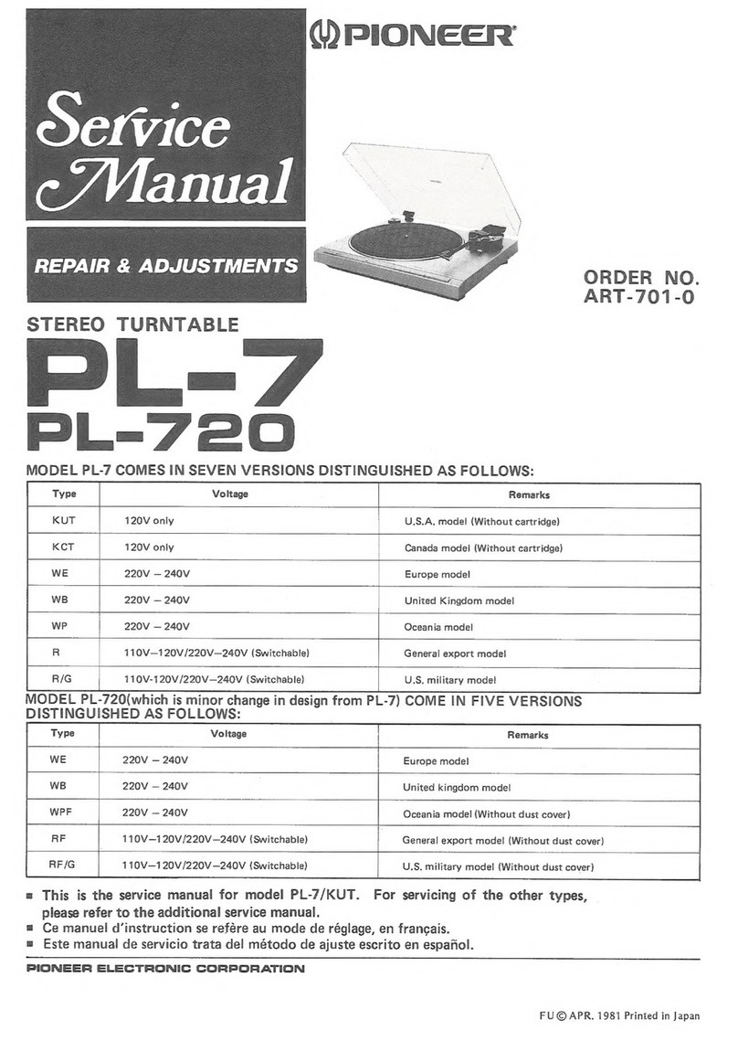
Pioneer PL-4 User manual

Service
PAL
ETUIET
REPAIR
&
ADJUSTMENTS
ORDER
NO.
ART-709-0
STEREO
TURNTABLE
L.—<}
PL-320
MODEL
PL-4
COMES
IN
SEVEN
VERSIONS
DISTINGUISHED
AS
FOLLOWS:
Remarks
120V
only
U.S.A.
model
(Without
cartridge)
120V
only
Canada
model
(Without
cartridge)
220V
—
240V
Europe
model
220V
—
240V
United
kingdom
model
220V
—
240V
Oceania
model
110V—1
20V/220V—240V
(Switchable)
General
export
model
110V—120V/220V—240V
(Switchable)
U.S.
military
model
MODEL
PL-320
COMES
IN
FIVE
VERSIONS
DISTINGUISHED
AS
FOLLOWS:
Voltage
Remarks
220V
—
240V
Europe
model
220V
—
240V
United
kingdom
mode!
220V
—
240V
Oceania
model
110V—120V/220V—240V
(Switchable)
Generali
export
mode!
110V—1
20V/220V—240V
(Switchable)
U.S.
military
model
(Without
dust
cover)
=
This
is
the
service
manual
for
model
PL-4/KUT.
For
servicing
of
the
other
types,
please
refer
to
the
additional
service
manual.
®=
Ce
manuel
d’instruction
se
refére
au
mode
de
réglage,
en
frangais.
=
Este
manual
de
servicio
trata
del
método
de
ajuste
escrito
en
espajiol.
PIONEER
ELECTRONIC
CORPORATION
4-1.
Meguro
1-Chome,
Meguro-ku,
Tokyo
153,
Japan
U.S.
PIONEER
ELECTRONICS
CORPORATION
&5
Oxford
Drive,
Moonachie,
New
Jersey
07074,
U.S.A.
PIONEER
ELECTRONIC
(EUROPE)
N.V.
Luithagen-Haven
9,
2030
Antwerp,
Belgium
PIONEER
ELECTRONICS
AUSTRALIA
PTY.
LTD.
178-184
Boundary
Road,
Braeside,
Victoria
3195,
Australia
FU
©
APR.
1981
Printed
in
Japan
=
For
the
circuit
and
mechanism
descriptions,
please
refer
to
the
supplement
of
model
PL-7
service
manual
(ART-768).
CONTENTS
1.
SPECIFICATIONS
...........2
000s
eee
2
2.
FRONT
PANEL
FACILITIES..............
3
3.
DISASSEMBLY
...
0...
eee
ee
ee
eee eee
4
4,
TROUBLESHOOTING.
...........00
000
es
6
5.
PRECAUTIONS
FOR
REASSEMBLY........
10
6.
BLOCK
DIAGRAM..........
00ers
12
7.
P.C.
BOARDS
CONNECTION
DIAGRAM.....
13
1.
SPECIFICATIONS
Motor
and
Turntable
Drive
System
1.0...
eee
teen
eae
Direct-drive
IMG
BOF
sister,
ly
ecncte
te
cabin,
bes
gris
Sens
Dhansel
ROEUE,
Cate
Hen
eee
iets
DC
servo
motor
Turntable
Platter.
.........310mm
diam.
aluminum
alloy
die-cast.
SPECS
ye
865
suh
fisidanctivns
elhenttw
oem
Wamesianace6
Alea
33-1/3
and
45rpm
Wow
and
Flutter
.............02
000
Less
than
0.025%
(WRMS)
Signal-to-Noise
Ratio..............--.
More
than
78dB
(DIN-B)
(with
Pioneer
cartridge
model
PC-3MC)
Tonearm
TY
Dh
are
oes
Aucune
ee
ecole
Static-balance
type,
Straight
pipe
arm
Effective
Arm
Length
..........2--2
2200-2
eee
eee
221mm
Overhang:
escaped
acess
dow
ogc
Gee
ert
acs
ale
de
aa
15.5mm
Usable
Cartridge
Weight
........-.-..
3g
(min.)
to
8g
(max.)
Subfunctions
Auto-return
mechanism,
Anti-skating
force
control,
Stylus
pressure
direct-readout
counterweight,
Cueing
device,
Strobe
light,
Free
stop
hinges
Miscellaneous
Power
Requirements.
...........
00
0
ee
es
AC120V,
60Hz
Power
Consumption
...........000
0000
cece
OW
Dimensions
..............
420(W)
X
108(H)
X
367(D)mm
16-1/2(W)
X
4-1/4(H)
X
14-7/16(D)in.
Weight
0
.'65
5.0.
Sg
iy
ee
vslare
A
gh
Bla
teen
plete
5.8kg/12
ib
12
oz
2
8.
SCHEMATIC
DIAGRAM...............-
15
9.
EXPLODED
VIEWS
.............-.00.0.
17
10.
ELECTRICAL
PARTS
LIST..............
22
11.
ADJUSTMENTS.
..........00.-
2002
eee
23
REGLAGE.
cal
tyies
cea
uae
naam
24
AIJUST
Eee
ie
GGA
Reh
Ae
eed
Ea
ee
25
12.:-PAGKING
cc
8d
4s
Saas
ore
whee
ee
26
Accessories
EP
Adapters
5.3.22
foes
Se
lense
ce ek
tee
ee
he
WS
Rte
SEN
ie
1
Operating
Instructions...
2...
...0.0.0.00.000.
000
eee
ee
1
NOTE:
Specifications
and
design
subject
to
possible
modification
without
notice,
due
to
improvements.
:
:
3
7
i
q
a
a
:
thigh
a
i
i
ir
aS
2.
FRONT
PANEL
FACILITIES
eS
®
eo
©
()
CUT
switch
Depress
this
switch
to
stop
play.
(2)
Speed
check
window
Look
through
this
window
and
observe
the
movement
of
the
striped
pattern
when
checking
the
rotational
speed
or
finely
adjusting
the
speed.
The
position
of
the
striped
pattern
differs
according
to
the
power
line
frequency
(50
Hz
or
60
Hz)
in
the
area
of
use
and
the
speed
(33
or
45
rpm)
of
the
platter.
Top
pattern:
For
45
rpm
in
50
Hz
area
Second
pattern:
For
45
rpm
in
60
Hz
area
Third
pattern:
For
33
rpm
in
50
Hz
area
Bottom
pattern:
For
33
rpm
in
60
Hz
area
(3)SPEED
ADJ
control
Rotate
this
control
in
order
to
finely
adjust
the
speed
of
the
platter.
The
speed
is
reduced
when
the
control
is
rotated
in
the
[-
]
direction.
The
speed
is
increased
when
the
control
is
rotated
in
the
[+]
direction.
(4)
SPEED
switch
Set
this
switch
in
accordance
with
the
speed
of
the
re-
cord
which
is
to
be
played.
[33]
(depressed
position):
[45]
(released
position):
©)
Cartridge
For
33-1/3
rpm
records
For
45
rpm
records
(6)
Headshell
@
Tonearm
(8)
ARM
ELEVATION
lever
Operate
this
lever
when
starting
record
play
or
when
temporarily
suspending
play.
@
ANTI-SKATE
control
This
is
rotated
when
performing
the
anti-skating
adjust-
ment.
Arm
rest
This
serves
to
hold
and
clamp
the
tonearm.
When
moving
the
tonearm,
release
the
clamp.
(})
Tracking
force
adjustment
weight
This
is
used
when
adjusting
the
tracking
force.
(2
Platter
(3)
Platter
mounting
shaft
Rubber
mat
(5)
EP
adapter
This
is
used
when
playing
records
without
a
‘‘middle.”’
(16
Cabinet
(7)
Dust
cover
3.
DISASSEMBLY
3.1
PANEL
AND
BASE
In
removing
the
panel,
follow
the
below
listed
steps
in
the
order
given.
Using
any
unnecessary
force
will
result
in
bending
the
springs
or
damaging
other
parts.
Panel
removal
steps
1.
Remove
the
headshell
and
weight
assembly,
and
the
weight
shaft
assembly.
The
weight
shaft
assembly
is
removed
by
loosening
screw
(Hexagone
socket
screw)
and
the
headshell
by
loosening
screw
@
.
2.
Lift
off
the
turntable
platter.
Turntable
platter
3.
AD
oP
Panel
Motor
—
assembly
|
|=
Ae
|
omen
EN
Base
Dust
cover
Loosen
insulator
attachment
screws
@
and
remove
the
insulator.
(Do
not
mix
the
color-
coded
float
springs.
They
must
be
replaced
with
their
original
insulators
during
reassemb-
ly.)
.
Remove
the
rear
panel
PU
cord
strain
relief.
-
Unplug
the
2P
and
5P
connectors.
.
Completely
remove
the
PU
cord
from
the
panel.
Lift
up
the
headshell
end
of
the
tonearm,
and
taking
care
not
to
damage
the
tonearm,
remove
it
from
the
panel.
(Hold
the
tonearm
steady.)
Weight
assembly
Screw
8
Rubber
bush
Control
mechanism
assembly
Insulator
z
Fig.
3-1
Disassembly
3.2
D.D
MOTOR
ASSEMBLY
After
the
panel
has
been
removed,
loosen
the
three
motor
attachment
screws
@
and
remove
the
motor.
3.3
TONEARM
SECTION
Remove
the
tonearm
section
by
taking
out
the
three
arm
base
attachment
screws
@
and
one
ground
wire
securing
screw@.
3.4
CONTROL
MECHANISM
SECTION
After
the
tonearm
section
has
been
removed,
loosen
the
three
control
mechanism
attachment
screws
@and
remove
the
assembly.
Tonearm
PU
plate
Fig.
3-3
Remove
tonearm
3.5
TONEARM
1.
Disconnect
the
tonearm
lead
wires
from
the
PU
board
(See
Fig.
3-2).
Note
that
some
of
the
lead
wires
have
been
soldered
to
the
PU
board,
and
must
be
discon-
nected
with
care.
2.
Loosen
the
set
screw
@
with
a
screwdriver
to
remove
the
PU
plate
under
the
arm
base
(See
Fig.
3-3).
8.
Undo
the
screw
@
securing
the
tonearm
to
the
arm
base
(See
Fig.
3-3).
Tonearm
lead
wires
PU
board
Red
Fig.
3-2
Disconnect
the
tonearm
lead
wires
(Hexagone
socket
screw)
Arm
base
4.
TROUBLESHOOTING
Use
the
following
directions
to
find
the
cause
of
each
type
of
breakdown.
Improperly
adjustment
units
should
be
completely
readjusted.
«
AUTO-RETURN
DOES
NOT
WORK
Change
in
starting
position
adjust-
ment.
Starting
plate
does
not
follow
the
NO
Too
much
grease
between
the
signal
signal
plate.
plate
and
the
cam
YES
YES
Inner
diameter
of
the
starting
plate
hole
is
small.
Protrusions
on
the
caulk
section
of
the
starting
plate
hole.
Not
enough
grease
between
the
starting
plate
and
signal
plate.
After
starting,
incomplete
reset
of
the
NO
The
curved
section
of
the
signal
signal
plate.
(See
Section
1)
plate
is
deformed.
YES
Arm
lead
wire
is
caught
on
something.
PU
cord
is
touching
the
PU
plate.
The
inner
areas
of
records
can
not
be
tracked.
Operator
of
the
detection
lever
is
not
smooth.
Looseness
in
the
PU
plate
attach-
ment.
Section
1
After
performing
the
return
operation,
if
the
curved
section
of
the
signal
plate
and
curved
sect-
ion
of
the
starting
plate
are
not
in
contact
with
surfaces
A)
and
respectively
of
the
cam,
reset
will
be
incomplete
and
the
starting
position
will
be
late.
As
a
result,
the
return
function
may
not
operate
at
times.
In
this
case,
bend
the
signal
plate
©)so
that
dimension
(A)
is
0.5mm
or
larger.
Cam
Fig.
4-1
Incomplete
reset
of
starting
and
signal
plates.
Starting
plate
:
At
least
0.5mm
0
see
ee
IS
it
Bae
Lay
ot
a
a
=»
RETURN
IS
FAST
(RETURN
AT
1mm
PITCH)
Protrusions
on
the
pinion
gear
section
(See
section
2)
Section
2
Pinion
gear
If
there
are
rough
areas
of
plastic
protruding
Protruding
section
from
the
(A)
section
of
the
protruding
section
of
the
pinion
gear,
the
return
function
may
operate
at
a
pitch
of
only
1mm.
In
this
case,
remove
the
Fig.
4-2
Elimination
of
pinion
gear
protrusions
plastic
protrusions
completely
(Fig.
4-2)
»
MOTOR
DOES
NOT
ROTATE
2P
and
5P
connectors
are
not
attach-
ed.
YES
Connector(s)
is
not
properly
installed.
=
MOTOR
DOES
NOT
STOP
The
switch
lever
and
switch
locker
No
The
installation
location
of
the
PU
are
not
locking
(See
section
3)
plate
is
incorrect.
Section
3
|
PU
plate
In
order
to
turn
the
power
OFF,
the
PU
plate
shaft
touches
surface
®
of
the
switch
locker
pushing
it
over
so
it
locks
with
the
switch
lever
turning
the
microswitch
OFF
(Fig.
4-3).
If
the
amount
of
push
on
the
switch
locker
is
insuf-
ficient,
it
can
not
lock
with
the
switch
lever.
With
the
tonearm
locked
in
the
arm
rest,
as
shown
Switch
lever
|
in
figure
4-4,
attach
the
PU
plate
precisely
mid-
Mads
rel
Peers
Gr
switch
Iocker
way
between
the
first
and
second
points
from
the
arm
base
scale
mark
counting
away
from
you.
Pte:
Arm
base
scale
mark
Fig.
4-4
Adjustment
PU
plate
«
MOTOR
ASSEMBLY
NOTE:
The
IC
PA2008
used
in
the
PXM-090
does
not
have
a
dedicated
ground
pin
for
its
internal
circuitry,
but
uses
the
thermal
fan
ground.
When
replacing
the
IC,
make
sure
the
securing
screws
retaining
the
ground
line
between
the
IC
and
thermal
dissipator
and
between
the
thermal
dissipator
and
motor
base,
and
base
to
circuit
board
is
securely
tightened.
e
Motor
Does
not
Turn
are
Component
connected
to
Is
Vee
1
29
volts?
Me
rh
supply
circus
detec:
PA2008
terminal
4
defec-
YES
:
tive.
LA
ane
eae
term
NG
PA2008
defective.
NO
YES
Is
PA2007
terminal
11
less
|no
|
PA2007
defective
or
parts
Poor
PA2008
Tab
terminal
than
3.5
volts?
connected
to
PA2007
to
GND
contact.
YES
terminal
11
defective.
Is
PA2008
terminal
3
|NO
PA2008
defective
over
1.0
volt?
;
®
Motor
Does
not
Stop
Hall
element
defective
or
Hall
element
bias
resistor
defective.
Is
Hall
voltage
DC
bias
Ha:
15-17
volts;
Hb;
4-6
volts:
When
the
motor
is
rotated
by
hand,
is
Hall
voltage
(Ha,
Hb)
generated?
If
resistance
is
high,
coil
wire
is
open;
if
resistance
is
low,
PA2008
is
defective
or
coil
is
shorted.
R5_
defective
or
printed
circuit
open.
With
power
OFF,
is
DC
resistance
between
PA2008
terminals
12—14
and
1—13
60
ohms?
With
power
OFF,
is
DC
resistance
between
PA2008
terminals
7—2
3.9
ohms
YES
PA2008
defective.
e
Motor
Runs
away
Is
Vee
1
29
volts?
NO
Power
supply
circuit
de-
fective.
YES
:
—
|NO
NO
Is
PA2008
terminal
4
10
PA2008
defective.
Parts
connected
to
PA2008
11
volts?
terminal
4
defective.
YES
: :
NO
Is
FG
signal
input
to
?
PC
pattern
open
in
FG.
YES
Parts
connected
to
PA2007
;
NO
serie
oir
i
to
terminal
13
defective
or
PC
ermina
‘
pattern
open.
YES
PA2007
defective
or
parts
connected
to
PA2007
terminal
14
defective.
Is
FG
signal
output
from
PA2007
terminal
14
over
12V
p-p?
NO
YES
Slow
down
the
motor
at
about
33
1/3
rpm
with
a
;
hand,
is
the
prescribed
NO
PA2007
defective
or
Cl
defective.
waveform
output
from
PA2007
terminal
4?
YES
Slow
down
the
motor
at
aoe
33
1/3
rpm
Wes
a
|No
PA2007
defective
or
C3
hand,
is
the
prescribed
:
defective.
waveform
output
from
PA2007
terminal
1?
YES
PA2007
defective,
or
C2
defective,
or
parts
connect
When
the
motor
is
stopped
by
hand,
is
the
output
Is
the
potential
between
PA2007
terminal
5-6
0.5—0.8
volts?
between
PA2007
terminal
5-6
defective.
from
PA2007
terminal
11
less
than
3.5
volts?
YES
PA2008
defective.
5.
PRECAUTIONS
FOR
REASSEMBLY
Follow
these
directions
and
precautions
when
reassembling
a
unit
after
completing
repairs.
Be
sure
to
lubricate
as
required,
make
no
mistakes
when
attaching
parts,
and
avoid
all
other
careless
mistakes
that
may
be
the
cause
of
trouble
later
on.
5.1
AREAS
THAT
REQUIRE
LUBRICATION
NOTE:
Types
of
lubricants
and
areas
where
they
are
used
are
listed
in
table
1.
Table
1
Areas
used
Type
of
Oil
Silicon
Oil
#50000
raising
shaft
GYA-008
all
other
areas
Lubrication
points
are
specified
for
oils
other
than
GYA-008.
Never
use
a
different
type
of
oil.
e
Cam
Section
Apply
oil
to
the
heart-shaped
grooved
section
(rear
side
of
the
cam)
and
lock
plate
sliding
section
in
order
to
minimize
wear
on
the
sliding
section
and
the
burden
on
the
mechanism.
e
Driving
Plate
Assembly
Decrease
the
burden
on
the
mechanism
and
the
wear
on
the
sliding
section.
Sides,
top,
and
bottom
surfaces
e
(sliding
section
of
auto-stop
S
mechanism)
Sides
surface
(sliding
section
of
auto-stop
mechanism)
Top
and
side
EV
cam
side
surface
(sliding
section
of
elevation
cam)
Fig.
5-1
Driving
panel
assembly
section
switch
locker
section
¢
Switch
Locker
Section
Apply
oil
to
the
switch
locker
(opening)
and
sub-panel
base
sliding
section
to
decrease
the
burden
on
the
mechanism.
When
applying
oil
to
the
opening
(shaft
hole),
do
not
apply
any
oil
2—3mm
from
the
bottom
surface.
If
oil
is
applied
2—3mm
within
the
bottom
surface,
it
may
come
out
the
bottom
and
go
between
the
switch
lever
and
sub-panel
base
causing
the
switch
lever
to
operate
ineffectively.
10
Switch
locker
Fig.
5-2
Switch
locker
section
e
EV
Lever
Unit
Section
Apply
oil
to
the
sliding
section
of
leaf
spring
(A)
and
EV
lever
unit
to
decrease
the
burden
on
the
mechanism.
Leaf
spring
(A)
sliding
section
EV
lever
unit
4
EV
lever
unit
sliding
section
|
cane
\
Arm
base
\
Fig.
5-3
EV
lever
unit
section
e
Elevation
Cam
Section
Apply
oil
to
the
elevation
cam
and
sliding
sec-
tion
of
the
raising
shaft
to
decrease
the
burden
when
operated.
Elevation
cam
Fig.
5-4
Elevation
cam
section
e
EV
Sheet
Section
Apply
oil
to
the
raising
shaft
and
sliding
section
of
the
bearing
to
assure
stability
in
the
elevation
lowering
speed.
eit
ee
i
Sas)
Sin
et,
Apply
all
around
at
a
width
of
1mm
Half
of
the
grooved
section
EV
sheet
assembly
Fig.
5-5
EV
sheet
section
5.2
PRECAUTIONS
FOR
ATTACHMENT
OF
PARTS
AND
REASSEMBLY
e
Motor
Attachment
When
installing
the
motor,
set
the
cam
in
the
mechanism
stop
location
and
verify
that
the
starting
plate
section
does
not
protrude
be-
yond
surface
(A)of
the
cam.
If
the
motor
is
at-
tached
with
the
starting
plate
section
(B)
protrud-
ing,
the
starting
plate
may
be
deformed,
the
motor
pinion
gear
may
be
scratched,
and
the
returm
function
may
be
damaged.
Signal
plate
Starting
plate
a
Fig.
5-6
Motor
attachment
e
PU
Plate
Attachment
Push
the
PU
plate
into
place
so
that
the
PU
plate
bearing
section
touches
the
revolution
shaft
attachment
nut.
Installation
direction
is
as
shown
in
figure
5-7.
Pe
Arm
base
scale
mark
Fig.
5-7
PU
plate
attachment
e
AS
Knob
Attachment
When
installing
the
AS
knob,
put
the
AS
knob
rib
against
the
AS
knob
revolution
control
stopper
(attached
to
the
arm
base)
and
affix
with
the
screw.
As
the
stopper
may
break,
be
sure
to
press
the
AS
knob
down
firmly
when
installing
it.
se
aa
Fig.
5-8
AS
knob
attachment
Stopper
e
Arm
Base
Attachment
When
attaching
the
arm
base
section
to
the
mechanism
section,
put
the
mechanism
section
switch
locker
and
switch
lever
in
the
locked
posi-
tion
and
verify
that
the
tonearm
is
in
the
arm
rest
location.
Also
be
sure
to
put
the
manual
elevation
lever
in
the
up
position
and
check
that
the
PU
plate
shaft
is
in
the
position
shown
in
figure
5-9.
PU
plate
shaft
Switch
lever
Switch
locker
Fig.
5-9
Arm
base
attachment
e
Wiring
the
Connector
When
attaching
the
wires
to
the
2P
connector
from
the
microswitch,
bend
the
lead
wires
from
the
connector
housing
as
shown
in
figure
5-10
before
attaching.
Lead
wires
Connector
housing
Fig.
5-10
Wiring
the
connector
11
6.
BLOCK
DIAGRAM
ROTATIONAL
CONTROL
PA2007
#P-V
CONVERTER
—
CONVERTS
REFERENCE
PHASE
TO
VOLTAGE
(0C).
LOCK
RISCRIMINATOR
CIRCUIT
%
F-V
CONVERTER
—
CONVERTS
FREQUENCY
TO
VOLTAGE
(DC).
Panis
srnocn
|
eo
(16)
O
45
TP2
Q
Ps
SPEED
MOTOR
DRIVE
vec
2
!0V
CONSTANT
VOLTAGE
CIRCUIT
ROTATIONAL
DIRECTION
INDICATOR
=
IC
PA20O07
TERMINAL
WAVEFORMS
(AT
CONSTANT
SPECIFIED
ROTATION
)
age
REVERSE
ROTATION
4-
a
Ceneree
Ea
iin
FORMATION
about
1
mV
rms
SPEED
DETECTION
Vee
1
WAVEFORMS
IN
(1)
THRU
(@)
ARE
PASSED
THROUGH
BUFFER
AMP
|
ki
!
SMe?
sTOP
OISCRIMINATOR
CIRCUIT
12
PL-4
r
2
3
A
5
6
7.
P.C.BOARDS
CONNECTION
DIAGRAM
MOTOR
CONTROL
ASSEMBLY(PWM-O6O)
CONTROL
ASSEMBLY
®&WM-0O57)
<2>
<3>
<4>
<5>
POWER
SUPPLY
ASSEMBLY
(XWR-OO6)
POWER
TRANSFORMER
a
Ee)
RED
NEON
S!:
POWER
0.01/1
AC1I20V
6OHz
13
1
2
3
4
S:
6
D
1
2
3
4
8.
SCHEMATIC
DIAGRAM
MOTOR
CONTROL
ASSEMBLY
(PWM-060)
—
VR1
OPERATING
POINT
ADd
(33
pm)
1c
1
PA2007
P-066
VR2
OPERATING
POINT
ADJ
(45rpm)
SPEED
CONTROL
PCP-O056
cl
IC2
PA
2008
MOTOR
DRIVE
1c2
50*70mA
2
RF
L
|
-
TA
PTT-II9
NEON
PEL
-046
AC
POWER
CORD
PO0G-023
AC
l20v
60Hz
(0)
45rpm
—33'/3rpm
See
ce-
pee
aay:
"D2
IW
2-300
Pe
lrret
i
si
POWER
POWER
SUPPLY
ASSEMBLY
CONTROL
ASSEMBLY
(XWM-057)
Dw
eos)
External
Appearance
of
Transistors
and
ICs
2sD985
PA2007
PA2008
1.
RESISTORS:
Indicated
in
2,
%W,
+5%
tolerance
unless
otherwise
noted
k
:
k2,
M:
MQ,
(F)
:+1%,
(G)
:
+2%,
(K)
:
10%
(M)
:
+
20%
tolerance
2.
CAPACITORS:
Indicated
in
capacity
(uF)/voltage
(V)
unless
otherwise
noted
p
:
pF
Indication
without
voltage
is
50V
except
electrolytic
capacitor.
3.
VOLTAGE,
CURRENT:
S__]
:
DC
voltage
(V)
at
no
input
signal
<=]
mA:
DC
current
at
no
input
signal
4.
OTHERS:
@
:
Adjusting
point.
The
mark
found
on
some
component
parts
indicates
the
im-
portance
of
the
safety
factor
of
the
part.
Therefore,
when
replacing,
be
sure
to
use
parts
of
identical
designation.
This
is
the
basic
schematic
diagram,
but
the
actual
circuit
may
vary
due
to
improvements
in
design.
SWITCHES:
Si:
POWER
ON
—
OFF
$2:
SPEED
33'73
rpm
—45rpm
The
underlined
indicates
the
switch
position.
5
6
16
©
ft
o2
|
3s
|
4a
|
5s
|
¢
9.
EXPLODED
VIEWS
9.1
EXTERIOR
Motor
assembly
See
page
21.
EE,
=
ear
ac
as
|
Mechanism
assembly
See
page
20.
52:
iN
Ba
a
a
Ne
OR
tah
co
een
hia,
aaa
Oe
Parts
List
kk
xk
+
tt
16.
17.
18,
19,
20.
21,
22.
23.
24,
25,
26.
27,
28.
30.
31,
32.
33.
34,
35.
36.
37.
38.
39.
40.
PNV-034
PXB-155
PEA-057
PNR-164
PTT-119
PLZ40P120FMC
PNX-279
PAD-088
PAM-076
PNX-292
PAC-086
PPZ30PO080F
MC
PAM-078
PAD-093
XWR-006
PXB-241
IPZ30PO80FMC
PEL-046
PNX-298
PEB-194
XWM-057
PNX-293
PBA-118
PDG-023
PEC-056
PDE-064
PBA-124
PBA-108
PXM-090
PDZ30PO50F
MC
PXA-882
PPD-624
PXB-227
PXB-247
ZMD40HO80F
BT
ZMR30H150F
ZK
PNX-341
IPZ30P100FMC
VBZ30PO80F
MC
PAC-100
NOTES:
e
Parts
without
part
number
cannot
be
supplied.
e
The
/\
mark
found
on
some
component
parts
indicates
the
importance
of
the
safety
factor
of
the
part.
Therefore,
when
replacing,
be
sure
to
use
parts
of
identical
designation.
e
For
your
Parts
Stock
Control,
the
fast
moving
items
are
indicated
with
the
marks
xk*
and
*
.
%&%*
GENERALLY
MOVES
FASTER
THAN
*
This
classification
shall
be
adjusted
by
each
distributor
because
it
depends
on
model
number,
temperature,
humidity,
etc.
Description
Dust
cover
Hinge
assembly
Rubber
mat
assembly
Turntable
platter
Power
transformer
(120V)
Screw
Panel
SP
knob
(A)
unit
Front
name
plate
(C)
Switch
lever
(B)
Adjustment
knob
Screw
Front
name
plate
(E)
C
knob
unit
Power
supply
assembly
Cut
pole
assembly
Screw
Neon
lamp
Lens
holder
Damper
cushion
Control
assembly
Holder
Screw
Power
cord
Strain
relief
PU
cord
Screw
Screw
Motor
Screw
Headshell
assembly
Tonearm
assembly
EV
sheet
assembly
Tonearm
rest
assembly
Screw
Screw
Tonearm
base
Screw
Screw
AS
knob
46.
47.
48.
49.
50.
51.
52.
53.
54,
55.
56.
57.
58.
59.
60,
61.
62.
63.
64.
65.
66.
67.
68.
69.
101.
102.
103.
104,
105,
106.
107.
108.
109.
110.
PBF-017
PBH-292
PBE-012
PNX-335
PBH-308
PXB-231
PMD40P080F
MC
PNX-301
PNX-336
PBK-053
PXT-462
PBH-238
PBH-293
YE50S
PNX-339
YE30S
YS40F
BT
WC40FMC
PNC-227
PBH-295
PBH-294
PXT-596
PBA-535
PNT-554
PXB-501
PNX-303
PNC-217
PBH-307
PBA-086
Description
Washer
Spring
AS
spring
washer
AS
plate
PU
plate
spring
PU
plate
(B)
assembly
Screw
PU
plate
(A)
EV
cam
Jever
EV
plate
spring
(A)
EV
plate
spring
(B)
unit
EV
cam
spring
EV
spring
E-type
washer
EV
cam
E-type
washer
Fixed
washer
Plate
washer
PU
plate
spring
washer
Spring
Spring
Weight
shaft
unit
Screw
Rubber
bush
Weight
assembly
Switch
lever
Base
(B)
Spring
Screw
Connector
Strobe
holder
Mirror
Cut
base
Base
Strain
relief
Lead
unit
(GND)
Adjust
cam
Rubber
bush
PU
cord
assembly
19
dhe
iii
ict
a
a
i
mane
/
|
2
|
3
|
9.2
MECHANISM
ASSEMBLY
Parts
List
1.
PBA-126
2.
PYY-100
3.
PXT-446
4.
PSF-018
5.
PMZ26P100FMC
6.
PEC-065
7.
PBH-224
8.
PNC-220
9.
PBA-123
0.
PNX-031
9.3
MOTOR
ASSEMBLY
(PXM-090)
Description
Mark
No.
Screw
11.
Cam
assembly
12.
Detector
lever
unit
13.
Microswitch
14,
Screw
EV
cam
buffer
101.
Start
plate
spring
102.
Start
plate
103.
Screw
104,
Switch
lock
angle
Parts
List
Mark
No
ie
2.
3.
4.
10.
11,
12,
PNX-030
PNX-035
PBH-225
PDZ30PO50F
MC
Part
No.
PXT-458
PSZ30PO50F
MC
PWM-060
Description
Switch
lever
Lock
plate
Lock
plate
spring
Screw
Connector
assembly
Driving
plate
assembly
Protection
plate
Sub-panel
unit
Description
Rotor
unit
Screw
Motor
control
assembly
E
ring
(ETW-12)
Base
Heat
sink
Shaft
holder
21
i
}
|
;
i
E
10.
ELECTRICAL
PARTS
LIST
NOTES:
e
When
ordering
resistors,
first
convert
resistance
values
into
code
form
as
shown
in
the
following
examples.
Ex.
1
When
there
are
2
effective
digits
(any
digit
apart
from
0),
such
as
560
ohm
and
47k
ohm
(tolerance
is
shown
by
J=5%,
and
K=10%
).
§602
56
x
10°
561.....
RD“4PS
BEM
J
47RQ
47
x
10°
473
......
RD4PS
AM)
J
0.52
ORS
sci
ees
Cee
ee
RN2H
K
12
OLD:
bce
teen
tetas
RSiP
OMG
K
Ex.
2
When
there
are
3
effective
digits
(such
as
in
high
precision
metal
film
resistors).
5.62k2
562
x
10°
5621
....
RN%SR
GERM
F
e
The
4,
mark
found
on
some
component
parts
indicates
the
importance
of
the
safety
factor
of
the
part.
Therefore,
when
replacing,
be
sure
to
use
parts
of
identical
designation.
e
For
your
Parts
Stock
Control,
the
fast
moving
items
are
indicated
with
the
marks
«xx
and
*®
.
**
GENERALLY
MOVES
FASTER
THAN
*
This
classification
shall
be
adjusted
by
each
distributor
because
it
depends
on
model
number,
temperature,
humidity,
etc.
Power
Supply
Assembly
(XWR-006)
Mark
Part
No.
Symbol
&
Description
Mark
Part
No.
A
PCL-036
C1
Capacitor
CEA
100P
35
A
RS2PF
103J
R1
Resistor
CEANL
R22M
50
CEA
R47P
50
Control
A
WM-
ssembly
(X
057)
RESISTORS
SEMICONDUCTORS
Mark
Part
No.
Symbol
&
Description
*&
*&
2SD985-K
Qi
<<
Wibe
D1
Mark
Part
No.
*
W2Z-300
D2
RD
1/4
PM
Ooog
RD1/2PS
3R9J
SWITCH,
CAPACITORS
and
RESISTORS
RN1/4PR
363G
Mark
Part
No.
Symbol
&
Description
i
ipa
*&
&
PSG-029
$2
CEA102M
59L
C2
CE
RATOMIGEE
3
SEMICONDUCTORS
CKDYF103Z
50
C4
Mark
Part
No.
*
PCS-016
VR1
%&
%&
PA2007
RS1PF222J
R2
*&
*
PA2008
OTHERS
Motor
Control
Assembly
(PWM-060)
CAPACITORS
Mark
Part
No.
COMA
123K
50
CKDYF
104Z
50
COMA
473K
50
CKDYF
473Z
50
CEA
100P
16
CKDYF
103Z
50
CEA
010P
50
CEA
101P
10
CKDYF
2032
50
CSZA
R22M
35
22
Symbol
&
Description
C1
c2
C3
C4
c5
C6
C7,C14
cg
Cc9—C12
C13
Mark
Part
No.
*
PCX-039
Symbol
&
Description
C15-C19
C20
C21
NOTE:
When
ordering
resistors,
convert
the
resistance
value
into
code
form,
and
then
rewrite
the
part
no.
as
before.
Symbol
&
Description
R2—R4,R6—R9
R5
Ri
VR1
(47k-B)
VR2
(33k-B)
Symbol
&
Description
1C1
IC2
Symbol
&
Description
HA,HB
Hall
element
11.
ADJUSTMENTS
11.1
AUTO-RETURN
ADJUSTMENT
1.Turm
the
auto
return
adjustment
screw
full
around
counter-clockwise.
2.
When
the
auto
return
adjustment
screw
is
turn-
ed
back
a
little
at
a
time
clockwise,
the
to-
nearm
will
commence
to
return
to
the
outer
circumference.
3.
Stop
turning
the
adjustment
screw
once
the
stylus
tip
is
33mm
away
from
the
center
shaft.
4.
Once
the
above
adjustment
procedure
has
been
completed,
check
that
the
tonearm
returns
automatically
as
designed.
11.2
ARM-ELEVATION
ADJUSTMENT
To
proceed
with
the
elevation
sheet
height
adjustment,
insert
the
hexagonal
wrench
(for
3mm)
into
the
hole
at
the
front
of
the
EV
sheet
and
rotate
it
clockwise
to
reduce
the
height
and
counter-clockwise
to
increase
the
height.
The
height
of
the
stylus
tip
from
the
record
surface
is
7+2mm.
11.3
MOTOR
OPERATING
POINT
ADJUST-
MENT
1.
Press
the
START/STOP
button
to
start
the
turntable.
2.
Set
the
player
speed
adjustment
knob
to
the
mechanical
center.
3.
Adjust
the
semi-fixed
resistor
on
the
motor
control
assembly
so
that
the
strobo
stops.
(Fig.
11-3)
Screwdriver
Ae:
Fig.
11-1
Auto-return
adjustment
Elevation
sheet
Fig.
11-2
Arm-elevation
adjustment
VR2
(45rpm
adjustment)
Screwdriver
VR1
(33
1/3rpm
SEL
Se
57
adjustment)
/
(Bottom
of
motor)
Fig.
11-3
Motor
adjustment
23
|
3
}
;
q
eR
EERE
FORT
ERE
RN
EE
PRY
Ie
TN
Re
ALS
ee
eT
11.
REGLAGE
11.1
REGLAGE
DU
RETOUR
AUTOMATI-
QUE
DU
BRAS
1.
Tourner
la
vis
de
réglage
du
retour
automatique
du
bras
4
fond
dans
le
sens
contraire
des
aiguil-
les
d’une
montre.
2.
Lorsque
la
vis
de
réglage
du
retour
automatique
du
bras
est
tournée
d’une
petite
quantité
dans
le
sens
des
aiguilles
d’une
montre,
les
bras
de
lecture
commence
a
retourner
vers
la
péri-
phérie
du
plateau.
3.
Arréter
de
tourner
la
vis
de
réglage
lorsque
l’extrémité
de
la
pointe
de
lecture
se
trouve
a
33mm
de
|’axe
central.
4.
Lorsque
le
réglage
décrit
ci-dessus
est
terminé,
vérifier
que
le
bras
de
lecture
retourne
auto-
matiquement
de
la
maniére
désirée.
11.2
REGLAGE
DE
LA
MONTEE
DU
BRAS
Pour
régler
la
hauteur
de
la
plaque
de
montée,
introduire
une
clé
hexagonale
(de
3mm)
dans
le
trou
situé
devant
la
plaque
“EV”
et
la
tourer
dans
le
sens
des
aiguilles
d’une
montre
pour
réduire
la
hauteur,
ou
dans
le
sens
contraire
des
aiguilles
d’une
montre
pour
augmenter
la
hauteur.
La
hauteur
de
l’extrémité
de
la
pointe
de
lecture
au-
dessus
de
la
surface
du
disque
est
de
7
+2mm.
11.3
REGLAGE
DU
POINT
DE
FONCTIONNE-
MENT
DU
MOTEUR
1.
Appuyer
sur
la
touche
START/STOP
pour
faire
démarrer
le
tourne-disque.
2.
Régler
le
bouton
de
réglage
de
vitesse
de
la
platine
sur
la
position
mécanique
centrale.
3.
Régler
la
résistance
ajustable
de
1’assemblée
contréle
de
moteur
a
ce
que
le
motif
stroboscopi-
que
s’arréte
(Fig.
11-3).
24
Fig.
11-1.
Réglage
du
retour
automatique
du
bras
Plaque
de
montée
Fig.
11-2
Réglage
de
la
montée
du
bras
oO
Tournevis
VR2
(réglage
de
45
tpm)
(dessous
du
moteur)
Fig.
11-3
Réglage
de
la
vitesse
du
moteur

This manual suits for next models

1

Other Pioneer Turntable manuals

Pioneer PL-5 User manual

Pioneer

Pioneer PL-5 User manual

Pioneer PL-55X User manual

Pioneer

Pioneer PL-55X User manual

Pioneer PL-670 User manual

Pioneer

Pioneer PL-670 User manual

Pioneer N-30AE User manual

Pioneer

Pioneer N-30AE User manual

Pioneer PL-990 User manual

Pioneer

Pioneer PL-990 User manual

Pioneer PL-55DX User manual

Pioneer

Pioneer PL-55DX User manual

Pioneer PL-X420 User manual

Pioneer

Pioneer PL-X420 User manual

Pioneer PL-560 User manual

Pioneer

Pioneer PL-560 User manual
Pioneer PL-51A User manual

Pioneer

Pioneer PL-51A User manual

Pioneer PL-200Z User manual

Pioneer

Pioneer PL-200Z User manual

Pioneer CDJ-2000NXS User manual

Pioneer

Pioneer CDJ-2000NXS User manual

Pioneer PL-500 User manual

Pioneer

Pioneer PL-500 User manual

Pioneer PL-560 BK User manual

Pioneer

Pioneer PL-560 BK User manual

Pioneer PL-3000/HB User manual

Pioneer

Pioneer PL-3000/HB User manual

Pioneer PL-512 User manual

Pioneer

Pioneer PL-512 User manual

Pioneer PL-55DX User manual

Pioneer

Pioneer PL-55DX User manual

Pioneer PL-450 User manual

Pioneer

Pioneer PL-450 User manual

Pioneer N-30AE User manual

Pioneer

Pioneer N-30AE User manual

Pioneer PL-200 User manual

Pioneer

Pioneer PL-200 User manual

Pioneer PL-600 User manual

Pioneer

Pioneer PL-600 User manual

Pioneer PL-41 User manual

Pioneer

Pioneer PL-41 User manual

Pioneer PL-530 User manual

Pioneer

Pioneer PL-530 User manual

Pioneer PL-510A User manual

Pioneer

Pioneer PL-510A User manual

Pioneer LC-V4300C User manual

Pioneer

Pioneer LC-V4300C User manual

Popular Turntable manuals by other brands

GPO 170.615 instruction manual

GPO

GPO 170.615 instruction manual

Gadhouse Brad retro manual

Gadhouse

Gadhouse Brad retro manual

Sony PS-X7 Owner's instruction manual

Sony

Sony PS-X7 Owner's instruction manual

audiophony TT-2930 operating instructions

audiophony

audiophony TT-2930 operating instructions

Crosley Anthology instruction manual

Crosley

Crosley Anthology instruction manual

Kenwood KD-600 Service manual

Kenwood

Kenwood KD-600 Service manual

JB Systems q3 usb Operation manual

JB Systems

JB Systems q3 usb Operation manual

Marantz NA6005 Service manual

Marantz

Marantz NA6005 Service manual

Rehan i-Speak user manual

Rehan

Rehan i-Speak user manual

Dual CS 435-1 operating instructions

Dual

Dual CS 435-1 operating instructions

Micro Seiki BL-111 manual

Micro Seiki

Micro Seiki BL-111 manual

Pyle Vintage PTTCSM70BT user manual

Pyle

Pyle Vintage PTTCSM70BT user manual

auna TT-18SB manual

auna

auna TT-18SB manual

Lindemann LIMETREE NETWORK manual

Lindemann

Lindemann LIMETREE NETWORK manual

Rega P2 quick start guide

Rega

Rega P2 quick start guide

Teac TN-400BT-X owner's manual

Teac

Teac TN-400BT-X owner's manual

Numark TT-1650 operating instructions

Numark

Numark TT-1650 operating instructions

LENCO L-90 user manual

LENCO

LENCO L-90 user manual

manuals.online logo
manuals.online logoBrands
  • About & Mission
  • Contact us
  • Privacy Policy
  • Terms and Conditions

Copyright 2025 Manuals.Online. All Rights Reserved.