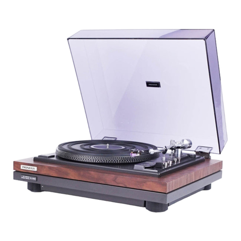
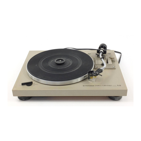
Pioneer PL-51A User manual

SERIrICE MANIIAL
<ART-126 0>
STEREO TURNTABLE
,r"t,I
jPL-5IA
KUT
., I
, l'
,l
<75CO2M61 K> ()rrroNEEFu

PL-5IA
CONTENTS
1. SPECIFTCATTONS . .
2. OPERATION..i. ..
3. PRINCIPLE OF MOTOR OPERATION. .
4. ADJUSTMENT
5. EXPLODED VNEWS AND PARTS LIST
5.1 Facking .
5.2 Mechanism. .
6. SCHEMATIC DIAGRAMS, P.C. BOARD PATTERN AND PARTS
6.1 Schmatic Diagram . .
6.2 Power Supply Circuit Assembly (KWR-030) . . .
LI ST
.4
.5
.6
.7
.8
. l',|
. '16
.17

1. SPE CtF|CAT|ONS
PHONO MOTOR AND TURNTABLE
Motor. .. Dcservomotor
Speed . Two speeds: 33-1/3 rpm, 45 rpm
Wow and flutter . . . . 0.05% (WRMS) or less
S/N ' . . . 58dB or more (in case of using Pioneer cartridge model
PC.50)
Turntable platter. 3lcm diam, Aluminum-diecast alloy
TONEARM
Tonearm type. . . . . Static balance, S-shapq, pipe arm
Effective arm length 221mm
Tracking error *3o--1o
Overhang 15.5mm
Usable cartridge weight . . . . 49 (min)-'l4g (max)
SUBFUNCTIONS
Large-size shock absorbers
Anti-skating force control
Lateral balance weight
Oil-damping arm elevator
H inges ( F ree-adjustable)
Speed fine adjusters (33-1/3rpm.45rpm: for use in turntable speed adjustment with stroboscope
and strobolight)
OTHERS
Power requirements AC. 120V,60H2
Powerconsumption. . .. .. . 5.2W(max)
Outerdimensions.. 480(W) x410(D) xt85(H)mm
18-718(W) x 16-1/8(D) x 7-114(Hl in.
Weight . . . 11.b kg, 26 tb
ACCESSORY GROUP
Overhangadjustmentgauge. .......1
45 rpm adaptor 1
Weight plate (Cartridge weight-adjustable) 1
Head shell 1
Sub weight. l
Screwdriver 1
Output cord (Connection cord) 1
iiii*ffiffill--' . .. .' ..'. .. .. .. .. .. .. .. .. .. ., .. .. .. .. .. . '?
NOTE: Specificationsandthedesignsub.iecttopossiblemodilicationwithoutnoticeduetoimprovements.

2. OPERATIO'U
STROBOSCOPE
The proper part
depend upon the
below.
and STROBOLIGHT
ffiL*ffiXA
$s"113 RPhd BUT5ON
Push this but,ton for playing a
record "
33-1/3 rpn'r speed
45 RPh{ BUTTON
Push this button for playing a
cord. 45 rpm speed re-
33 113 rpm
45 rpn'l
SPEED CCINT'ROL KNOBS
with either of tire speed selectors pressed, watch
the appropriate stroboscope band and slroboright.
Adjust for precise speed (so t,hat the band appears
to stand still) by turning that speed cont,rol knobs.
Turn toward + {clockwise } for fasten speecl o to_
warri (counterr:lockwise) frlr slower. When the
stroboscope appears to stand still, the speed is cor-
rect.
of the stroboscope band
power source and record to read
speed as
\\
STROEOSCOPE
50H z
60H z
50Hz
60Hz
33 1/3 rprn
45 rpnr
ST R OBOL IG HT
FUNCTION LBVER
This three-stage lever turns the motor on ancl off.
and raises and low,ers the tonearm .
o OFF Position
Shuts off power the motor, Stopping platter
rotation.
o ON-UP Position
Switched from OFF this position causes the
platter to begin moving and switch on the
strobolight.
Switched from DOWN it, raises the tonearm so
that the stylus leaves the record surface smooth-
ly.
o DOWN Position
When you are ready to begin record play move
the lever to this position and stylus r+'ill lower
gerrtly onto the record.
@
rc
46:(ffi-
33 1/3 rpm
45 rpm

3. PRINCIPLE OF MOTOR OPERATION
Construction of motor control for the PL-51A
is depicted in Fig. 2.
1. Applying power sets the oscillator into
operation. Output of this circuit passes to
the pole position detecting circuit (L1-LG).
2. Here, assume that coupling between L1 and
L4 is the tightest. Voltage induced in L4 is
rectified and applied to Q106/Q109 in the
driver.
3. Q109 in turn conducts and causes current to
flow in the associated drive coil (A-1). The
rotor moves in the direction shown by arrow
in Fig. 1. The magnetic pole affixed to the
rotor induces a voltage proportional to rotor
movement, in the sensing coil (A-4).
4. Voltage induced in A-4 is rectified by a
diode in the speed sensor and applied to
Q103 in the control stage. This point is also
fed from the reference voltage generator
(voltage Es)through a fine speed control pot.
5. Voltage applied to the base of Q103 in the
control stage controls current that flows in
Q104.
6. Q104 serves as a constant current source for
Q106 through Ql1 1 in the driver and
therefore controls current flow in the drive
coils.
7. When ambient temperature change causes
driver current to rise, the speed of rotation
increases above the rated value. Q104 current
increases and Q106-Q111 currents decrease. pOLE pOStTtON
As a result, the speed of rotation falls off. DETECTOR
OSCI LLATOR REFERENCE VOLTAGE
GENERATOR
POLE POSITION
DETECTOR
Pole Position Detector
Fig. 1 shows a simplified view of the drive and
sense coils. With power applied and coupling
between L1 and L4 high, Q109 causes current
to flow through A-1. As a result, the rotor end
of coil A-i becomes a south pole (S1) and
attracts N1. The rotor moves in the direction
shown by arrow. Coupling factor between L2
and L5 increases and operatior, of Q110 causes
current to flow in coil A-2. Pole S2 attracts pole
N2 and rotor rotation continues. In the same
manner, 53 attracts Pole N3. Continuation of
this process causes the rotor to turn on a steady
basis.
DIRECTION OF
ROTATION
CONTROL STAGE
Fig. 1
DRIVE SENSING
cotLS cotLs sPEED SENSO
ROTOR
Lr
Lz
L3
DRIVER Fig.2

4. ADJUSTM ENT
When adjustment of the fine speed control
does not give a satisfactory speed, adjust the
motor in accordance with the following
procedure.
1. Remove the bottom cover.
2. Set the fine speed control to the midposition.
3. While observing the edge of the turntable
platter with a strobe, adjust screws inside the
motor as shown in Fig. 3.
4. Alternate switching between 33-1/3 and
45 rpm speeds while making adjustment.
Make sure that both speeds are correct.
Selection of Line Voltage
If model PL-51 does not agree with the line
voltage of your service area, set the unit to the
proper line voltage as follows:
1. Remove the bottom cover, now you can see
the terminal board (Fig. ).
2. Unsolder the lead (White) from the terminal.
3. Solder the lead (White) to the terminal of
your local line voltage.
WH ITE
P.C. BOARD
NOTES:
N)
5
o
l\)
o
J
w('
OOO
TERMINAL BOARD
POWER TRANSFORMER
FL-5IA
First set knob
to midposition
Fis. 3
1 10V
1 20V
1 30V
220V
240V
YELLOW
BROWN
ORANGE
RED
GRAY
J-<...a.- \
6ry
Use screwdriver
for adiustment
Fig. 4

5. EXPLODED VIEWS AND PARTS LIST
5.1 PACKING
NOTICE: Any parts asterisked(*) are subject to being not supplied.
Key No. Description Part No.
1
2
3
6
7
o
q*
'l 0
10-1
11*
12
13
14
15
16
17
18
19
20
21
22
1a
24
25
26
2t*
2A
29*
30
31*
32
33
O-
Rubber mat
Rubber mat ring
Card board
Rubber mat bag
345x395x0.05(t)mm
Vinyl bag
Operati ng instructions
Top packing
Dust cover
Dust cover bag
70Ox650x0.05(t)mm
Styrotector (A )
Styrotector (B )
Unit {PL-51}
Vinyl cover
Furnished parts box
Screwd river
EP adaptor
Main weight assembly
Lateral balance weiqht
Set screw M4 x 5
Subweight A
Overhang checker
Parts Box cover
Connection caLrles
Weighr plate
Screw (13mm)
(11.5mm)
( 8mm)
( Smm)
(15mm)
Washer
Vinyl bag 5O x 70 x 0.O3(t)mm
Nut
Head Shell
Turntable platter
Vinyl bag
345x395x0.05(tlmm
Packing case
Packing stopper
Rubber mat assembly
KEB-058-0
KAH-OO7.A
H 52-632-0
E11-O24-O
KRB.064.4
KHC-059-0
KNK.266-4
KHA.226-B
KHA.221-A
H 56-603-0
KHX-026-B
KEX-OO2-A
KNK-055-B
KXA-566-A
KXA.42O.B
KLA-131-O
KNK-290-0
KH X -027-0
PDE.OO4.A
N64-698-A
811-044-C
B 11-657-0
KBA-043-0
K8A-044-0
KBA-045-O
823-642-O
871-653-4
KNH -108-0
PHG-034-0
KHK4OSO
KEA-019-0
Attached 1 9
8


PL-5IA
The following symbols stand for screwsj nuts, washers, etc.
as shown in EXPLODED VIEW on pp. 9-10.
N.... nut
FW..... flatwasher
SW..... springwasher
E...... E-typewasher
T.... Tappingscrew
Parts List of Mechanism
NOTES:
Sems A: Screw and spring washer
Sems B: Screw, spring washer and f lat washer
Sems F: Screw and flat washer
NOTICE: Any parts asterisked (*) are subject to being not supplied
Key No. Description Part No.
1
2
J
4
5
t)
1
o
o
10
11
12
1a
14
15
17
18
19
20
21
22
a1
24
26
27
28
29
30
JI
32
JJ
34
35
JO
a1
Rubber mat ring
Rubher mat
Turntable platter
Dust cover
Ovalcountersu nk head screw
M4x10
Lock plate
Pan head sems A screw M4 x I
Motor
Motor hlase
Power transformer
Transformer base rubber A
Transformer holder
Pan head sems F screw M4 x 15
Boss
Power supply circuit Ass'y
Cord fixer
Boss
Terminal board {5P)
Pan head screw M4 x 12
Wood screw 3.1d x 13
Upper board
lnsulator (G)
lnsulator (H)
Power cord grommet
P late
Lamp cover
Strobo lamp
Pan head sems F screw M3 x
cord
Adaptor catch
Pan head sems F screw M3 x
Spring hinge assembly
Wood screw 3.1d x 13
12
15
KAH-OO7-A
KEB-058-A
KNH-108-0
KN K-266-A
N61-084-0
KXM.O21.G
KNA-572-F
KTT-015-0
KEB-063-0
KNA-603-A
KN K.186.,A
KWR-O30.E
KEX-004-0
KN K-186.4
KKE-006-B
KMwl-093-A
KXA-796-B
KXA.797-B
E32-056-0
KNA-522-C
KAK-046-0
K E L-OO4-C
KDX-O06.A
KLA-601-0
KXA-603-B
(or KTT-016-0)
13

Key No. Description Part No.
JO
39
40
41
42
AA
44
45
46
47
48
49
50
51
52
53
54
55
56
57
58
59
60
61
62
b-J
64
btJ
6l
68
69
7A
71
72
73
74
75
16
77
78
Under board
P late
Tapping screw M3 x 10
Washer 4d
Pan head sems A screw M3 x 5
Main weight assembly
Sub weight A
Elevator arrn
Elevation shaft
Set screw M2.6 x 2
Washer
Spri ng
Washer
Arm base
Arm clamp
Arm rest
Clamp pin
R est stand
Set screw M2"6 x
Knob
Wood screw 3.1d x 16
Arm board
Spri ng
Arm lift plate
Pan head sems A screw M3 x 5
Lifter shaft angle
Cable
Terminal strip (1L4P)
Lift plate
Pan head sems A screw M3 x 5
Leaf spri ng
Pan head sems A screw M3 x 5
Push button
Button shaft
Spri ng
Lifter base
Pan head sems A screw M4 x 6
Bail lever
Spri ng
KNA-629.E
KAM-090-0
KXA-566.A
KLA-131-0
KXA-392-0
KLA-350.A
KBE-008-0
KBH-O22-A
KNA.125-A
PNW-001-0
PNW-O28.A
PNW-027.A
KLA-1 11-0
KLA-240-0
KLA-s,I 8.A
KNA-761-0
KBH-066-A
KNA-328-O
KXA,583-A
PDA-001-0
KKC-021-O
KNA-576-0
KBK.O16-4
KLA.527.D
KLA-530-C
KBH-099-0
KXA.581.D
KNA-192.8
KBH-029.8
Attached 23, 24, 1O4
1,4
Parts List of Mechanism

PL-5IA
Key No. Description Part No.
79
80
ot
at*
83*
84
85
86.
8l-
B8
89
92
93
94
96-
97
98
99
100
101
102
103
104
105
106
101
1 08',
1 09'
110
111
1 12'
113
114
C
@
a3)
Pan head sems B screw M3 x 5
Pan head sems A screw M3 x 5
Leaf spring
Steel ball l5l32"l
Bail lever shaft
Rubber washer {t=1}
Tef lon washer
Lever
Spacer {A)
Microswitch
Pan head sems A screw M3 x 16
Potentiometer
( Fine speed adjustment)
Function lever
Cam
Power cord
Terminal board assembly
P late
P late
Wood screw 3.1dx 16
Pan head sems F screw M3 x 8
Bottom cover
Power supply P.C. board
Capacitor 0.0331.iF
Capacitor 0.01pF 1.4kV
Mylar tape
Terminal (B)
Fuse holder
Fuse 0.3A (Wired in type)
Terminal {L-shaped)
Fan head sems A screw M3 x 1O
Metal oxide 1Ok 2w
Tonearm assembly
Arm rest assembly
Operation mechanism assembly
KBK-016-4
KLA-154-0
KNA-191-B
KLA.155-B
KSF-023-0
KCS-006-A
KLA-574-O
KXA.582.A
KDG-01 1-0
KXA-s71-F
KNK-253-D
KNK-254-C
KMS-074-O
KNP.O65.A
KCE-009-0
c43-O03-0
KN K-222-0
K91-006-0
E21 -030-0
K28-003-0
RS2P 1O3J
PPD-520.A
PXA.O3O.A
KXA.664.G
Excluding head
Parts List of Mechanism
15

6. SCHEMATIC DIAGRAMS, P.C. BOARD PATTERN
AND PARTS LIST
6.1 SCHEMATIC DIAGRAM
R ch OUTRJT
L ch OUTPUTCF--
Eart h
52
PO$JER S}JITCH
LJl3L____i 0
POWER
Dros llZ-192
SUPPLY CIRCUIT ASS'Y
KWR-O3O-E
POIER P.C. BOARD
KNP- O5S-A TRANS FORI"lER
KTT-015
SPEED SELECTOR
swtTCH s r
-
(!
)<
O
STROBO LAI1P
5P TERMINAL Dtor-rM
srDol-01
r----'
!r rr*_t
L
16
25D234 HT---tr-, f,ll
t( ) l
,-l F---:-alsl
trll i | ,l

PL.5IA
6.2 POWER SUPPLY CIRCUIT ASS'Y (KWR-O3O}
Foil Side
r
ID,o, _,oo sIB0l-01 Q ro1 25DZ34
! rrsr
034
ID,o, wz-192 |
t-
r-- ___J
tr)
cf)
O
(.)
(')
-
()
O
CD
t
(v-
O
(-)
J)
c')
(-)
ct
FUSE O.3A . Croz
"4-
33/35
o
ol
o2
o
Dlor - Dto+
o-{f--o Hf.-.o
SIB0l-01 x 4
e-t(..+ e=fl+
o
o
E+;i *+i
o
o
:4
:3
?-
StH
*l- 6:''
6 2sD234
Cro: .
e#\
100/?5
o6
o
KWR-O3O-E o5
o
t7

. CAPACITORS: lN pF UNLESS OTHERWTSE NOTED p: pF
e RESISTORS: lN f,i,7aW UNLESS OTHERWISE NOTED k: ke. M:Mf,r
Parts List of Power Supply Circuit Assembly
CAPACITORS
Symbol Description Part No.
c1 01
c102
c1 03
Electrolytic
E lectrolytic
Electrolytic
330 35V
33 35V
100 25V
CEA 331P 35
cEA 330P 35
CEA 101P 25
RESISTORS
Symbol Description Part No.
R 101
R 102 Carbon film 680
Carbon film 680 RD%PS 681J
RD74PS 681J
SEMICONDUCTORS
Symbol
O1O1 Transistor 25D234 i
D101 Diode Sl801.Ol
D102 Diode 51801-01
D103 Diode 51801-01
D104 Diode SIBO1-O1
Dl05 Zener diode W2.192
OTHE RS
Symbol Description Part No.
Fuse 0.3A
Fuse holder E21-030-0
K9'l -006-0
18

I'IC,NEEFI ELECTFIONIC COEIPOFIATIGIN
a 1, 1-Chom--, Megu.o. M.glro ku Tokyo 153 J-p..
U,S. F'IONEEFl ELECTFIONICS COFIFC'FIATIG,N
75 Orfo.cr D.,wc Mc-,r-.h.. N,:.a J.rs-V O7a7a.tS A
PIONEEFI ELECTFIONIC (ELJFIOPE' N.V.
Mei.-Ce.Ler Mt: . 21, aOOO An.we.p. B.a!g!!,i
FIG|NEEFI ELECTFIONIC€i AL'SiTFIALIA PTY. LTO.
P56 A C iy Foad. Soutti Me bou.ne V'.t..,a 3eO5 Aust.ar'a
o MABCH 1Sl5
Table of contents
Other Pioneer Turntable manuals

Pioneer
Pioneer CDJ-2000nexus Instruction Manual

Pioneer
Pioneer AVH-P6500DVD User manual

Pioneer
Pioneer PL-530 User manual

Pioneer
Pioneer PL-55X User manual

Pioneer
Pioneer PL-500X User manual

Pioneer
Pioneer PL-4000 User manual

Pioneer
Pioneer PL-61 User manual

Pioneer
Pioneer PL-670 User manual

Pioneer
Pioneer PL-430 WE User manual

Pioneer
Pioneer PL-514 User manual

Pioneer
Pioneer DEH-P7550MP User manual

Pioneer
Pioneer pl-x50 User manual

Pioneer
Pioneer PL-990 User manual

Pioneer
Pioneer PL-12E PV User manual

Pioneer
Pioneer PL-A45D User manual

Pioneer
Pioneer PL-L70 User manual

Pioneer
Pioneer PL-115D User manual

Pioneer
Pioneer PL-55DX User manual

Pioneer
Pioneer PL-225 User manual

Pioneer
Pioneer CLD-1600 User manual