Piranha RELIANCE C1D1 Series User manual

INSTRUCTIONS FOR USE
40790xx-1 Piranha Blox C1D1 Series
Self-Retracting Device
Complies with the current ANSI Z359.14-2012 and all
applicable OSHA regulations and requirements.
Control Dynamics Inc.
DBA Piranha-Safety
21 E Marine View Dr Ste G
Everett, WA USA 98201
Phone: 425-513-9014
Toll Free: 800-738-5004
Email: contact@piranha-safety.com
Page 1

Instructions for Use
Page 2
Page 3
Contents
DESCRIPTION 3 - 6
PRODUCT SPECIFICATIONS 7
APPLICATION 8
A. PURPOSE............................................................................................................................. 8
1) PERSONAL FALL ARREST........................................................................................ 8
B. USE LIMITATIONS .............................................................................................................. 8
1) CAPACITY .................................................................................................................... 8
2) FREE FALL................................................................................................................... 8
3) FALL CLEARANCE...............................................................................................9 - 10
4) SWING PENDULUM FALLS..............................................................................10 - 12
5) CHEMICAL HAZARDS.............................................................................................. 12
6) HEAT............................................................................................................................................... 12
7) CORROSION ......................................................................................................12 - 13
8) ELECTRICAL HAZARDS .......................................................................................... 13
9) MOVING MACHINERY ............................................................................................. 13
10) SHARP EDGES AND ABRASIVE SURFACES...................................................... 13
11) WEAR AND DETERIORATION ................................................................................ 13
12) IMPACT FORCES...................................................................................................... 13
SYSTEMS REQUIREMENTS 14
A. COMPATIBILITY OF SYSTEM PARTS ................................................................................ 14
1) COMPATIBILITY OF COMPONENTS AND SUBSYSTEMS .................................. 14
2) COMPATIBILITY OF CONNECTORS
....................................................................... 14
3) ANCHORAGES AND ANCHORAGE CONNECTORS............................................. 15
INSTALLATION PROCEDURE 15
A. CONNECTING THE SRL TO AN ANCHOR POINT ...................................................... 15
B. CONNECTING THE SRL TO A HARNESS .................................................................... 15
C. PREPARATION FOR USE ................................................................................................ 16
D. INSPECT PRIOR TO USE ................................................................................................ 16
E. PLAN SCOPE OF WORK TO BE PERFORMED ANALYSIS)..............................17 - 18
CARE OF THE LANYARD 18 - 19
INSPECTIONS 19
A. INSPECTION FREQUENCY............................................................................................. 19
B. INSPECTION PROCEDURE .....................................................................................19 - 21
TRAINING 21
RESCUE PLANNING 22
SERVICING 22
GUARDING AGAINST APPLICATION FAILURE 22 - 23
WARNINGS AND LIMITATIONS 23 - 24
LABELING 24 - 27
INSPECTION RECORD 28
PART NUMBER LIST 29
WARRANTY STATEMENT 29
User Instructions
Reliance/Piranha-Safety Self Retracting Lifelines
User Instruction Manual - Self Retracting Lifelines
This manual is intended to meet the Manufacturer’s Instructions as required by
the current ANSI Z359.14(2012) ,and should be used as part of an employee
training program as required byOSHA.
WARNING:
This product is one part of a personal fall arrest, restraint, work
positioning, personnel riding, climbing, or rescue system. Without the other
necessary components in such sub-systems the self-retracting lifeline itself
serves no useful purpose. The user must follow the manufacturer’s instructions
for each component of the system. These instructions must be provided to the
user before using this product and retained for ready reference by the user. The
user must read, understand (or have explained), and heed all instructions,
labels, markings and warnings supplied with this product and with those
products intended for use in association with it before using this equipment.
Manufacturer’s instructions must be followed for proper use and maintenance
of this equipment. National standards and state, provincial and federal laws
require the user to be trained before using this product. This manual can be
used as part of a such a user safety- training program that is appropriate for the
user’s occupation.
IMPORTANT: Alterations or misuse of this product or failure to follow
instructions may result in serious injury or death.
If you have questions
on the use, care, or suitability of this equipment for your application,
contact Reliance/Piranha-Safety Fall Protection for information.

Instructions for Use
Page 4
Page 5
DESCRIPTION
The Piranha Blox
™
Self Retracting Lifeline (SRL) is designed to be a
component in a personal fall arrest systems (PFAS). It may be used in most
situations where a combination of worker mobility and fall protection is re-
quired (i.e. inspection work, general construction, maintenance work, oil
production, confined space work, etc.). The Piranha Blox
™
SRL is designed
for use by a single person weighing up to 310 lbs [140kg] (body weight
plus tools) *PLEASE NOTE -capacity is specific to lifeline model. See
Page 6 for complete details. Piranha Blox
™
Self Retracting Lifeline features
a cam-action pawl system ensuring positive lock-up even in the most de-
manding environments. The Piranha Blox
™
to be mounted overhead in
areas where there are no other convenient anchor points for personal
fall arrest means. The Piranha Lox swivel or anchor connector
(depending on model) provides an easy to see load indicator showing
whether the Piranha Blox
™
has been exposed to a fall arrest load and
needs to be serviced.
Identifying Components of Piranha Blox™ Self Retracting
Lifelines Figure 1
Fixed Anchor
Carry Handle
Housing
4079020-1
4079020-1
Mil-Spec Electrical
Connector
Piranha Lox Connector
Figure 2 4079020-1
Front Label
----Shown with optional GPH
Levers.

Instructions for Use
PRODUCT SPECIFICATIONS
The following specifications apply to all Piranha Blox™ and ™ Self Retracting Lifelines
and meet the Class B requirements of ANSI Z359.14-2012:
The following specifications apply to allPiranha Blox™ Self Retracting Lifelines and
meet the Class A requirements of ANSI Z359.14-2012:
• Maximum Arrest Force (MAF): ≤ 1,800 lbs (8kN) • Average Arrest Force (AF): ≤
1,350 lbs (4kN)
• Arrest Distance (AD): ≤ 24” (0.61m)
• 310 lb Max. Capacity: 1 worker, max. combined tool & body weight ≤310 lbs (140 kg).
Page 6
Page 7

Page 8
Page 9
Instructions for Use
SELF RETRACTING LIFELINE APPLICATION
A. PURPOSE:
Reliance/Piranha-Safety Self Retracting Lifelines (SRL’s) are used as one
component in a personal fall arrest system (PFAS). The SRL’s described in this
manual meet, ANSI Z359.14 and OSHA requirements (except where noted).
These instructions, and markings borne by the SRL’s, fulfill the instruction and
marking requirements of those standards and regulations. This equipment is
specifically designed to dissipate fall energy and limit the fall arrest forces that are
transferred to the body. The Interlocking feature of the Piranha Lox connector
makes operation of the tied in circuit to be non-operational until operator is safely
connected.
1) PERSONAL FALL ARREST:
The self-retracting lifeline is used as a component of a personal fall arrest
system. Personal fall arrest systems typically include a full body harness, a
connecting subsystem (energy absorbing device such as a shock absorbing
lanyard or self-retracting lifeline) and an anchorage connector. Average
arresting force must not exceed 900 lbs (4kN) for ANSI Z359.14-2012, Class
A and 1350 lbs (6kN) for ANSI Z359.14-2012,
Class B. Maximum arresting force must not exceed 1,800 lbs (8kN) for ANSI
Z359.14-2012 and OSHA.
B. USE LIMITATIONS:
Consider the following application limitations before using this equipment:
1) CAPACITY:
These SRL’s are designed for use by persons with a combined weight
(clothing, tools, etc.) of no more than 310 lbs (140kg) *Capacities vary -
please see Page 6 for full details.
3) FALL CLEARANCE:
There must be sufficient clearance below the user to arrest a fall before the
user strikes the ground or other obstruction. The clearance required is
dependent on the following factors (see Figure 4 for reference):
•Elevation of anchorage
•Connecting subsystem length
•Deceleration distance
•Free fall distance
•Worker height
•Movement of harness attachment element
2) FREE FALL:
Personal fall arrest systems used with this equipment should be mounted
overhead in such a way as to eliminate the possibility of a free fall. Avoid
working above the anchorage level to avoid an increased free fall distance.
Avoid working where your line may cross or tangle with that of other workers
or objects.
WARNING!
Persons with muscular, skeletal, or other
physical disorders should consult
a physician before using. Pregnant women and minors must never use this
equipment. Increasing age and diminished physical fitness may reduce a
person’s ability to withstand shock loads during fall arrest or prolonged
suspen
sion. Consult a physician if there is any question about a user’s
physical ability to safely use this product to arrest a fall or remain suspended.
Do not allow the lifeline to pass under arms or between legs. Never clamp,
knot, or prevent the lifeline from retracting or being taut. Avoid slack line. Do
not lengthen the SRL by connecting a lanyard or other components without
consulting Reliance/Piranha-Safety.
WARNING!
CALCULATE THE FALL CLEARANCE!
1) Determine distance beneath walking/working surface to nearest
lower level or obstruction: Minimum Required Clearance - MRC
2) Add the Activation Distance - Distance required for lifeline to
activate -Activation Distance - AD = 12” (.3m)
3) Add the Deceleration Distance - DD. No more than 30”(.76m)
4) Add the Safety Factor: Safety Factor - SF. 1.5’ to 3’ (.4 to .9m)
AD + DD + SF < or = MRC

Instructions for Use
Page 10
Page 11
RIGHT WRONG
Figure 5
Figure 4
4) SWING PENDULUM FALLS:
Swing falls occur when the anchorage point is not DIRECTLY above
the point where a fall occurs. If the worker falls in such a situation,
there is a possibility of a swing fall that may bring him into contact
with objects below or to the side of him, possibly causing serious
injury or death. These objects must be removed or the SRL and/ or
anchorage point be repositioned directly over the worker to help
reduce the risk of a swing fall. A Competent Person or Qualified
Engineer should always be consulted if there exists a possibility ofa
swing fall occurring. The worker must be trained to understand that
the width of his allowable work area can never exceed the anchorage
height of the retractable over his walking/working surface.
For example, if a worker in a building with 10 ft (3m) floors walks 20 ft
(6m) away from his anchorage he could fall and strike the floor below
before his fall would extract any line from the SRL.
If an object is in his swing path (or that of the line) a hazardous
situation exists. Two factors become evident in this situation:
First, due to the swing fall, horizontal speed of the worker may be
high enough to cause injury if an obstacle in the swing fall path is
struck by either the user or the line (web). The hazard increases as
the initial (before fall) length of extended cable is increased and as
the initial angle which the cable makes with the vertical is increased.
In the extreme case where a user has extended 90 ft (27.4m) of line
at an angle of 30 degrees with the vertical, the user can theoretically
develop a horizontal speed of about 19mph (30.5km/h). By
comparison, if the user has extended 50 ft (15.2m) of line at an angle
of 15 degrees with the vertical, the user may develop a horizontal
speed of about 7mph (11km/h). This situation is clearly more
tolerable, but it may still be dangerous if hazards such as rigid or
sharp objects, electrical conductors, or powered equipment are in the
swing fall path.
The second factor that comes into effect in a swing fall is that the
total vertical fall distance of the user may be much greater than if the
user had fallen entirely vertically without a swing fall path. This

Instructions for Use
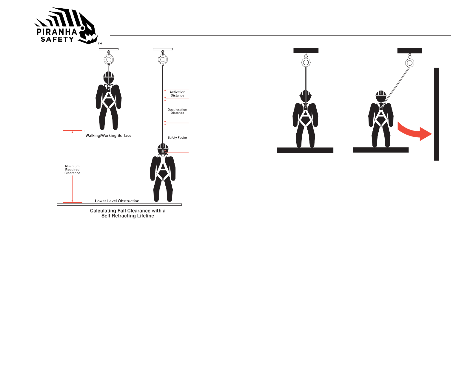
hazard also increases as the initial (before fall) length of extended
line is increased and as the initial angle which the line makes with the
vertical is increased. For example, if the initial extended line length
is 10 ft (3m), the drop at the bottom of the pendulum swing would be
1.3 ft (0.4m) This is in addition to the line extension due to the devices
internal shock absorption which may be as much as 3.3. ft (1m). The
total vertical fall distance would then be as much as 4.6 ft (1.4m) If,
however, 50 ft (15.2m) of cable is initially extended at a 30-degree
angle with the vertical, then a drop at the pendulum bottom of 6.7 ft
(2m) would result. In this example, adding the 3.3 ft (1m) of cable
extension due to internal shock absorption of the device, the total
vertical fall distance could be as much as 10 ft (3m).
Minimize swing falls by working as close to the anchorage point as
possible (see Figure 5). Do not permit a swing fall if injury could
occur. Swing falls will significantly increase the clearance required
when a self-retracting lifeline or other variable length connecting
subsystem is used.
5) CHEMICAL HAZARDS:
Acidic, alkaline, or other environments with harsh substances may
damage the webbing or synthetic rope (if equipped) and hardware
elements of this SRL. Polyester webbing is more resistant to attack
by acids but is subject to degradation by alkaline or neutral pH
environments. If working in a chemically aggressive environment, an
SRL that uses a cable lifeline is generally recommended. When
working in the presence of chemicals, more frequent inspection of
the SRL is required.
6) HEAT:
Do not use SRL’s that utilize a web lifeline in environments with
temperatures greater than 185°F (85°C). Protect the lanyard when
used near welding, metal cutting, or other heat producing activities.
Sparks may damage the line webbing or rope and reduce its strength.
7) CORROSION:
Do not expose the device to corrosive environments for prolonged
periods. Organic substances and salt water are particularly corrosive
to metal parts. When working in a corrosive environment more
Page 12
frequent inspection, cleaning, and drying of the SRL is required. For
the most severe environments the sealed SRL is recommended. See
Care and Inspection sections for cleaning and inspection details.
8) ELECTRICAL HAZARDS:
Use extreme caution when working near energized electrical sources.
Metal hardware on the SRL, the lifeline itself (on cable units), and on
other components connected to it will conduct electric current.
Maintain a safe working distance [preferably at least 10’ (3m)] from
electrical hazards.
9) MOVING MACHINERY:
When working near moving machinery parts (e.g. conveyors, rotating
shafts, presses, etc.), make sure that loose equipment is secured.
Maintain a safe working distance from machinery that could entangle
clothing, the lifeline, the harness, or other components connected to
it.
10) SHARP EDGES AND ABRASIVE SURFACES:
Do not expose web lifelines to sharp edges or abrasive surfaces that
could cut, tear or abrade and weaken the fibers. If working around
sharp edges and abrasive surfaces is unavoidable use heavy
padding or other protective barriers to prevent direct contact. An
energy absorbing component can sometimes be added in-line to
further protect the worker. Compatibility and total fall distance must
be considered if this is done. Contact Reliance/Piranha-Safety before
using an in-line energy absorbing component or lanyard with
an SRL. NOTE on Leading Edge SRL: Although this model provides
additional protection from falls occurring over edges, protection
against cutting must be provided when working near extremely
sharp edges such as sheared, cold rolled, or flame cut steel, or
rough cast edge concrete. Edge protection is not required over
edges such as hot rolled steel, steel decking, chamfered concrete,
or wood.
11) WEAR AND DETERIORATION:
Any SRL which shows signs of excessive wear, deterioration or
aging, must be removed from use and marked “UNUSABLE” until
destroyed. See detailed inspection procedures.
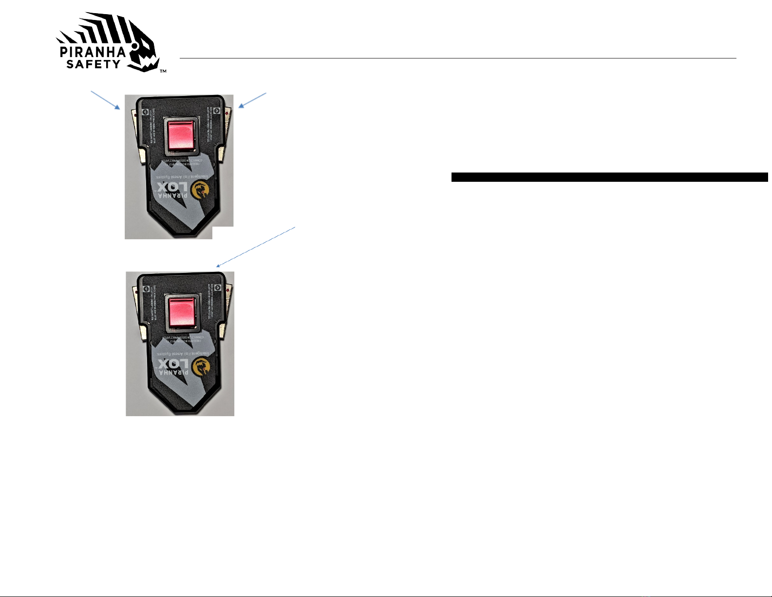
12) IMPACT FORCES:
Any SRL that has been subjected to the forces of arresting a fall
must be immediately removed from service and marked as
“UNUSABLE” until recertified or replaced. RELIANCE/PIRANHA-
SAFETY SRL’s have impact load indicators built into the anchorage
component on top of the SRL that facilitate inspection for fall
loading.
IMPORTANT: When working with tools,
materials, or in high temperature
environments, ensure that associated fall protection equipment can
withstand high temperatures, or provide protection for those items.
CAUTION!
Page 13

Instructions for Use
Page 14 Page 15
SYSTEMS REQUIREMENTS
A. COMPATIBILITY OF SYSTEM PARTS
1) COMPATIBILITY OF COMPONENTS AND SUBSYSTEMS: Piranha Blox
SRL's are designed to be used with Piranha-Safety approved components
and connecting subsystems. Use of the SRL with products made by others
should be evaluated by a competent person to ensure compatibility of
components and hardware. Connecting subsystems must be suitable for use
in the application (e.g. fall arrestor restraint). Piranha-Safety manufactures a
line of connecting subsystems for most applications.Contact Piranha-Safety
for
further in
formation.
Refer to
the
manufacturer's instructions supplied
with the component or connecting subsystem to determine suitability.
Contact Piranha-Safety with any questions regarding compatibility of
equipment used with the SRL.
2) COMPATIBILITY OF CONNECTORS
The Piranha Blox SRL is only compatible with Piranha-Lox Connector Inserts,
all Piranha-Lox Connector inserts are rated at 5,000 lb. (22 kN) minimum
breaking strength and comply with
ANSI
Z359 .12-2012. RELIANCE
connectors meet these requirements. Non-compatible connectors may
accidentally disengage ("rollout") or false engage. Connecting
subsystems (self-retracting lifeline,lanyard,rope grab and lifeline,cable
grab,etc.) must be suitable for your application.
3) Proper operation of Piranha Blox connectors
Attach Piranha-Safety Lanyard to Harness using the following steps:
A. Insert loop end of Lanyard through dorsal ring on Harness.
B. Hold
Piranha-Lox
connector insert in opposite hand
C. Feed connector insert through loop end of lanyard.
D. Pull
Piranha-Lox
connector insert until all slack is removed. This will form a
hitch loop on the dorsal ring. (FIG. A) and (FIG. B)
Connect
Piranha-Lox
Lanyard (attached to harness as specified above) to
the Piranha Blox SRL using the following steps:
A. Insert
Piranha-Lox
connector insert into connector on Piranha Blox SRL until
resistance is met
B. Depress the red gate on top of connector and push insert the rest of the way
into connector.(FIG. C)
C. Check side gates to ensure that they are fully retracted into the connector
body. Ared dot will be visible on the side gates if they are not fully retracted.
(FIG. D)
D. Pull on connector insert to verify that itisfully seated in the connector.
To disconnect from the Piranha Blox connector perform the following steps:
A. Depress red gate on top of connector.
B. While keeping red gate depressed, use other hand to depress the two side gates.
C. Pull insert out of connector while all 3 gates are still depressed.
4) Electrical System Compatibility.
The Piranha Blox intelligent SRL is capable of monitoring a tie off point to determine
when it is in use. It provides a contact closure when personnel are correctly tied off.
In order to utilize this feature, connect control circuit conductors to the supplied
Military connector per the diagram below. All electrical connections must be made in
accordance with applicable electrical codes and local standards. Failure to comply
with local and state electrical code may result in injury, death, or property damage.
Electrical ratings of Piranha Blox are: up to 170 Volts DC ¼ amp maximum.
EXAMPLES OF INAPPROPRIATE CONNECTIONS:
A. To a D-ring to which another connector is attached
B. In a manner that would result in a load on the gate.
C. In a false engagement, where features that protrude from the snap hook or
carabiner catch on the anchor and seem to be fully engaged to the anchor point.
D. To each other.
E. Directly to webbing or rope lanyard or tie-back.
F. To any object shaped such that the snap hook or carabiner will not close
and lock, or that could cause roll-out should a fall occur.
(FIG. A) (FIG.B)

Instructions for Use
Page 16
Page 17
(FIG. D)
1) ANCHORAGES AND ANCHORAGE CONNECTORS Anchorages for
personal fall arrest systems must have a strength capable of supporting a
static load, applied in directions permitted by the system, of at least: (a)
3,600 lb. (16 kN) when certification exists, or (b) 5,000 lb. (22.2 kN) in the
absence of certification. When more than one personal fall arrest system is
attached to an anchorage, the anchorage strengths set forth in (a) and (b)
must be multiplied by the number of systems attached to the anchorage.
This requirement is consistent with OSHA requirements under 29 CFR 1910
& 1926.
Anchorage connectors must be selected carefully. Eyebolts should not be
used if they will be loaded at an angle to their axis, unless the loads fall within
design parameters for such use. Weld-on lugs should not be less than 1/2 in
(12.7mm) in width and should not be made of steel with less than 50,000-PSI
yield strength. The proper stress areas and weld areas must be calculated to
assure proper safety. If in question, consult Reliance Industries Engineering
for proper design requirements.
INSTALLATION PROCEDURE
A. CONNECTING THE SRL TO AN ANCHOR POINT
NOTE: Approved fall protection must be worn during Piranha Blox™
Self-Retracting Lifeline installation at all times. Do not use
the SRL as a method of personal fall protection until the system
has been completely installed, inspected, and approved for use by
a Qualified Person.
1. Installation of the Piranha Blox™ Self-Retracting Lifeline begins
with the identification of a suitable anchor point. The anchor point must be
capable
of supporting a 3,600 lb (16kN) load where certification of load carrying
ability exists, or 5,000 lb (22.2kN) where certification does not exist. NOTE:
These strengths must be multiplied by the number of persons that will be
connecting to the anchorage point at any one time.
2. Pass a large carabiner or bow shackle (or other Reliance approved
connecting means) through the swivel eye or handle at the top of the
Piranha Blox™. This carabiner or bow shackle must be rated with a
minimum breaking strength of at least 5,000 lb (22.2kN) and must be
used for connecting to only 1 SRL at a time.
3.Secure the bow shackle or carabiner to the anchor point. If using bow shackle,
verify that it is a safety shackle and that the nut of the shackle has been fully
captured using a clevis pin or lock ring to prevent accidentally disengagement.
CAUTION!
GATEGATE
RED GATE
(FIG. C)

Instructions for Use
Page 18Page 19
When using a carabiner make sure that the gate has fully closed and
rotated into a locked position.
B. PREPARATION FOR USE
1. Once the Piranha Blox™ has been secured into position, extract a few
feet of
cable slowly to verify that there is tension on the line and the
retraction spring is functioning correctly.
2. Give the cable a quick, sharp tug causing the unit to lock-up providing
that the braking mechanism is operating correctly. Slowly allow the cable
to be retracted back into the unit under the power of the retraction spring.
Removal is the opposite of installation.
Installation methods are not limited to bow shackles or carabiners. Custom
brackets are available for permanent or specialized installations. Contact
Reliance/Piranha-Safety to help identify specific installation methods for
your situation.
C. MONTHLY INSPECTION BY COMPETENT PERSON:
Inspect the SRL and all components of the PFAS:
1) Inspect the SRL to verify that itis in serviceable condition. Examination of
the lanyard or cable for severe wear, cuts, burns, frayed edges, abrasion, or
other damage. Examine stitching for any pulled, loose, or torn stitches.
See Inspection section for details.
D. PLAN SCOPE OF WORK TO BE PERFORMED (JOB
SAFETY TASK ANALYSIS)
Plan procedures to safely perform tasks when using any components of a
PFAS. Some considerations are listed below (see APPLICATIONS, item B.
USE LIMITATIONS section for additional details);
1) Anchorage Selection. In addition to strength considerations, the
anchorage should be rigged to prevent a fall onto the structure when
considering 2) and 4) below.
2) Swing pendulum fall
3) Rough surfaces or unprotected sharp edges that could cut or abrade the
equipment if unprotected.
4) Workplace geometry
a) Free fall distance - Personal fall arrest systems used with this
equipment should be mounted overhead in such a way as to
eliminate the possibility of a free fall.
b) Deceleration distance - Maximum 42 in (1.07m)
c) Total fall distance - The sum of the activation distance and
deceleration distance plus a safety margin.
d) A careful examination must be made of the workplace by a Competent
Person before the selection or installation of Piranha Blox™ anchorage
points. Consideration must be given both to the movement of materials
(Will cranes be used to “fly” equipment or parts in?) and workers around
the workplace to ensure that potentially hazardous situations are
avoided.
e) Areas where overhead cranes or gantries are used must be examined to
verify that neither the moving loads or lifting wires can interfere or snag
the extended wire rope, web, or rope line of a Piranha
Blox™ SRL causing a worker to be dislodged.
f) Overhead lighting and electrical cables must also be identified to insure
that installation of the SRL is sufficiently far enough away so that the line
can never contact the wire creating an electrocution hazard.
g) Consideration of obstacles present in the work area must include ALL
locations that COULD be reached if the entire length of cable, rope, or
The line must always be released slowly and in a controlled manner when
rewinding the cable back into the unit; it should never be fully released in an
uncontrollable manner. Allowing the line to retract in an uncontrolled fashion
could cause damage to the SRL, the workplace, or other users in the area.
Always use a tagline attached to the Piranha Lox Connector
to help guide
the line back into the unit when it is installed too far overhead to reach
directly; this will also help in pulling the Piranha Lox Connector
down to the
user for connection to his harness.

Instructions for Use
Page 20 Page 21
web line were extracted from the SRL. Obstacles that pose no
threat when a worker is on a platform, for example, may be
exposed to a dangerous situation should he climb downwards or
moves laterally towards another work surface.
WARNING!
Do not use if inspection reveals an unsafe condition.
Always err on the side of safety.

Instructions for Use
Page 22 Page 23
h)The cable, rope, or web line used in SRL’s should be protected from
damage when passing over sharp edges or near objects where the
cable, rope, or web line could become lodged or
pinched through the use of edge protectors that are not abrasive
to the lifeline. When significant changes in angle are
encountered, directional sheaves should be used or the SRL
anchorage point should be relocated to a location that prevents
contact with the sharp edge.
i) Avoid installations where debris, contaminants, and other
objects falling from above could damage the Piranha Blox™
and/or its cable, rope, or web line.
j) Extreme caution must also be exercised when considering the
use of the Piranha Blox™ SRL as a means of fall protection in
areas where a user is working on a sloped surface such as a
pitched roof or tank bottom, or on piles of loose material (such as
grain or sand) that may shift or slide. If the user falls or begins to
slide on such asurface, the SRL may notbe extracted fast enough
for the device to lock-up (typically, the line must be extracted
around 5-6ft/sec. for the unit to lock-up,) and arrest the sliding fall.
The user might continue to slide over a roof edge, or into some
other hazardous zone causing injury or death. The use
of a travel restriction system or a work-positioning system may be
more appropriate for such location sand should be considered first.
Contact Reliance Engineering for help in selecting equipment for
these applications.
5) Rescue and Evacuation - The user and employer must have a rescue
plan in place, training in its use, and the means to implement it at
hand. The employer must have the ability to perform a rescue quickly
and safely. Do not plan to rely on others for rescue because
prolonged suspension can cause bodily injury or death.
CARE OF THE Piranha Blox™ SRL
A. Clean exterior by wiping away excess dirt, grease, or other materials
that might interfere with operation of the unit. Dry hardware with a
clean, dry cloth, and hang to air dry. Do not attempt to disassemble
the unit. A buildup of dirt, solvents, paint, etc. on the lifeline may
prevent the SRL from working properly, and in severe cases degrade the
webbing to a point where it weakens and should be removed from
service. More information on cleaning is available from Reliance/
Piranha-Safety. If you have questions concerning the condition of your
SRL, or have
any doubt about putting it into service contact Reliance/Piranha-Safety.
B. Store SRL’s in a cool, dry, clean environment. Avoid areas where
heat, oil, chemicals or their vapors may exist. Thoroughly inspect
after extended storage. Good safety practice requires separate
storage of unusable product from usable product.
INSPECTIONS
A. INSPECTION FREQUENCY
1) Acompetent person other than the user must inspect the SRL in
accordance with ANSI Z359.14-2012 as specified in the following
inspection schedule.
ANSI Z359.14 Inspection Schedule
Type of Use Application Examples Conditions of Use Inspection
Frequency
Frequent to
Light
Rescue and Confined
Space, Factory Main-
tenance
Good Storage Condi-
tions, Indoor or Infre-
quent Outdoor Use,
Room Temperature,
Clean Environments
Annually
Moderate to
Heavy
Transportation, Resi-
dential Construction,
Utilities, Warehouse
Fair Storage Condi-
tions, Indoor and
Extended Outdoor
Use, All Temperatures,
Clean or Dusty Envi-
ronments
Semi-Annually to
Annually
Severe to
Continuous
Commercial Con-
struction, Oil and
Gas, Mining
Harsh Storage Condi-
tions, Prolonged or
Continuous Outdoor
Use, All Temperatures,
Dirty Environments
Quarterly to
Semi-Annually
Record the results of each formal inspection in the inspection and
maintenance log as described below.
B. INSPECTION PROCEDURE
1) Prior to each use, the worker must inspect the Piranha Blox™Self-
Retracting Lifeline for any physical damage, wear, corrosion, or
malfunctioning parts. Verify that the load indicator is notvisible by
looking to see if the red slide is deployed at connector.

Instructions for Use
Page 24 Page 25
(Figures 11,). Once the load indicator has been deployed, the SRL
must be returned to aReliance/Piranha-Safety approved repair
facility for evaluation and recertification. Inspect load indicator
webbing on SRL’s with web lifelines. Remove from service if
stitching is broken and/or “Remove From Service “label is visible.
Deployed Load Indicator
2) The workershould also verify that conditions around the SRLlocation have not
changed that may affect its’ ability to arrest a fall, such as obstacles or
equipment directly below the anchorage point which might create a swing
fall.
3) Before every use, the worker should extract the cable, rope, or webbing line
approximately six cycles to reset the cable wrapping on the drum and to
examine it for defects that would affect its overall strength. These defects
would include but are not limited to weld strikes or burns, kinks, bends, “bird-
caging”, bulge spots, outer diameter thinning, broken or snagged wire
strands, broken or burned web or thread, etc. If the cable, rope or webbing
line is showing evidence of any of these defects, the unit should be removed
from service immediately until the cable, rope or webbing line is replaced
and re-certified. The ferrules of the cable, stitching of the rope splice, or
stitching of the webbing by the Piranha-Lox connector should also be
examined for cracks, deformation or broken and damaged stitching.
4) After the wire rope/web has been allowed to retract into the unit at a
controlled manner, the Piranha-Safety Connector should be pulled sharply to
verify proper lockup of the unit. If unit fails to lockup when pulled quickly, or if
the cable fails to retract properly after lockup, the unit must be removed from
service until repaired.
5) For SRL’s, If accessible carefully inspect the plastic housing for cracks or
fractures. Evidence of cracks or fractures requires factory-authorized
inspection. Scuffing and minor indentations that do not inhibit the retraction
of the unit are cosmetic issues.
6) If proper connection is not made the wired device will notoperate.
TRAINING
It is the responsibility of the employer to train all workers prior to using this system
(per OSHA 1926.503 (a)(1)). The employer shall provide a training program for
each employee who might be exposed to fall hazards. The program shall enable
each employee to recognize the hazards of falling and shall train each employee
in the procedures to be followed in order to minimize these hazards. The employer
shall assure that, as necessary, each employee has been trained by a competent
person qualified in the following areas:
1) OSHA regulations governing the use of horizontal lifelines.
2) Ability to recognize potential fall and workplace hazards.
3) Method of inspection of safety equipment.
4) Rescue procedures.
5) Installation and removal techniques.
Figure 11

Instructions for Use
Page 27
RESCUE PLANNING
Prior to system use, a rescue plan must be prepared, the workers must be trained
in its use, and the rescue equipment must be on hand to implement it in case of a
fall. Typical rescue plans include (but are not limited to) the following items:
1) List of equipment that must be readily accessible in the event of an
emergency and the names of those workers certified to use or operate that
equipment.
2) Emergency contact phone numbers (ambulance, hospital, fire
department…)andameans to contact them (cell phone, emergency
radio).
3) List of employees on the site, and the specific tasks they will perform to
effect the rescue.
4) The equipment that will be used to aid in the rescue of any worker should
be attached to structural anchorages independent of those used for the
personal fall arrest system. During installation of anchorages, tie-off and
equipment attachment hard points should be attached, and also clearly
marked in such a manner as to provide a means to rescue a worker in any
position along the worksite.
SERVICING
A Qualified Person trained in the inspection and servicing of system components
must carry out servicing of this system. The company’s safety officer should
maintain a record log of all servicing and inspection dates. The system and all
components must be withdrawn from service if subjected to fall arrest forces.
Those components may be returned to service only after being certified by a
Qualified Person. Only original Reliance/Piranha-Safety equipment and
replacement parts are approved for use in this system. Contact Reliance Industries
Engineering with questions and when in need of assistance.
GUARDING AGAINST APPLICATION FAILURE
To avoid property damage, injury or death, the User must take reasonable steps to
prevent “Application Failure”. An application failure may be any unacceptable use,
misuse, or application error on the part of the User or System Designer. Because
each end usermight use this product in a manner different from Reliance/Piranha-
Safety Industries testing platform, and because
the User might use this product in combination with other manufacturer’s
products in a manner not evaluated, contemplated, or tested by Reliance,
the User or System Designer is ultimately responsible for verifying or
validating the suitability and compatibility of this product for use in his
application or system. Whenever questions regarding proper use or
compatibility arise, please contact Reliance Engineering at (303) 424-
8650.
WARNINGS AND LIMITATIONS
1) Proper care should alwaysbe taken to visually scan the work area prior to
use. Remove any obstruction, debris, and other materials from, and beneath
the work area that could cause injuries or interfere with the operation of this
system. Be cautious of swing fall hazards if working anywhere but directly
belowthe anchoragepointof the SRLs. Be awareof the movements of others
using SRLs or shock-absorbing lanyards in close proximity, knowing that ifthe
lines become crossed or tangled and a fall occurs, the sudden motion could
pull others off balance and make rescue more difficult.
2) Do not release the cable, rope, or web line when extended and allow it to
retract back into the unit uncontrollably. Releasing the cable, rope, or web line
and allowing it to reel itself in uncontrollably could cause damage to the
Piranha Blox™ and or the connector. The cable, rope, or web line should be
allowed to retract slowly into the unit under its’ own power. If the unit is
too far overhead to permit this, then a tagline should be attached to the
connector to help control the line retraction.
3) In the course of use, do not allow the cable, rope, or web line to wrap around
arms or legs, or become entangled in clothing or other items. In the event of a
fall, they could cause injury, or prevent the Piranha Blox™ from functioning
properly. Any Piranha Blox™. Retracting Lifeline that has the load indicator
the swivel snap showing (deployed) has seen a fall-arrest load and must be
returned to Reliance/Piranha-Safety for evaluation, repair, and recertification.
Units must not be reset in the field or allowed to be used until recertification
has taken place.
4) Users should be familiar with pertinent regulations governing the use of this
personal fall arrest system and its components. Only trained and competent
personnel should install and supervise the use of this system.
Page 26

Instructions for Use
Page 28Page 29
5) Use only Reliance/Piranha-Safety supplied or qualified compatible
components.
6) Do not tie knots in the cable, rope, or web line of the unit. Tying knots in
cable, rope, or web line reduces the overall strength of the wire rope.
Only connect to the Piranha Blox™ by using the 18" non-shock absorbing
lanyard (P/N:999904-PL) to connect to the dorsal (back) D-ring of a full-body
harness. Do not cross lines with another worker. Should the lines become
entangled, a fall by one worker could dislodge others. Plan and place SRLs
to prevent workers from crossing safety lines.
LABELING
The illustrations on the following pages are representations of the actual labels that
appear on Piranha Blox™ Self Retracting Lifelines.
All the information on the SRL Specifications Label is important for the safe use of
this product, so the user should ensure that the label has not been removed and
that the descriptions it contains match the task and environment in which the
product is intended to be used. An inspection log is available on Page 28 of this
manual. The unit should be inspected by a Competent Person at periodic intervals
and at least monthly. As per these instructions, the unit should be tested for locking
before each use.
PRODUCT LABELS

Instructions for Use
Page 30 Page 31
PRODUCT LABELS

Instructions for Use
Page 32 Page 33
PRODUCT LABELS PRODUCT LABELS

Instructions for Use
EQUIPMENT RECORD
PART NUMBER
SERIAL NUMBER
DATE
MANUFACTURED
PURCHASE DATE
ASSIGNED TO
SPECIFICATIONS These Instructions Apply to the Following Part Numbers:
4079020-1
4079055-1
Page 34
Piranha Blox™ SRL’S
Certified to meet the current ANSI
Z359.14 and OSHA regulations for
the Self Retracting Lifeline
component of a complete personal
fall arrest system. Lanyard webbing
certified minimum 9000 lb. (4082kg)
breaking strength, all hardware
certified to 5000 lb. (22kN) breaking
strength, 100 percent proof tested
to 3600 lbs. (16.5kN).
Individually serial number and date
of manufacture are on product label.
Made in:
Texas, USA
Washington, USA
Warranty
Products manufactured by Reliance/Piranha-Safety Industries LLC are warranted against
factory defects in workmanship and materials for a period of two years from date of purchase
by the owner (end user) or for a period of one year from date first used, provided that this
period shall not exceed two years from date of shipment to distributor. Upon notice of product
defect or fault, Reliance/Piranha-Safety Industries LLC will promptly repair or replace all
defective items. Reliance/Piranha-Safety Industries LLC reserves the right to elect to have
any defective item returned to its manufacturing plant, authorized service center or distributor
for inspection before making a repair or replacement. This warranty does not cover
equipment damages or defects resulting from abuse, damage in transit, or other damage
beyond the control of Reliance/Piranha-Safety Industries. This warranty applies only to the
original purchaser and is the only one applicable to our products and services, and is in lieu
of all other warranties, expressed or implied. When products offered by Reliance/Piranha-
Safety Industries LLC are manufactured by a third party. Original equipment manufacturer
(OEM) warrantyshall applyandmay be outsidethe control of
Reliance/Piranha-Safety Industries LLC.
INSPECTION RECORD
DATE
INSPECTOR
PASS/FAIL
4079012-1
Page 35

Addition Information Piranha Blox Instruction Manual Addendum 05/07/2021
Applies to V1 – V9 Piranha Blox Instruction Manual Addendum 01-1
The following procedure must take place after install of The Piranha Blox Intelligent Safety
Retractable Device (SRD).
During shipping the SRD wire rope can settle and create a layover condition on the drum. The
following procedure will help reset the SRD wire rope on the drum for its intended vertical
hanging position.
•Hang SRD on the approved anchoring point and secure in place.
•Using a tagline or similar method, fully extend 100% of the cable and allow to retract
100% in a controlled manner. Repeat this action a minimum of 6 times to ensure correct
cable lay on the drum providing smooth operation of the SRD.
The above action should take place anytime the SRD is removed from its vertical hanging
position.
This manual suits for next models
4
Table of contents