Pite LB 3980 User manual

LB 3980 Battery Load Bank
User Manual
P-120921-V2.4

2
Catalogue
1. INTRODUCTION ................................................................................................................4
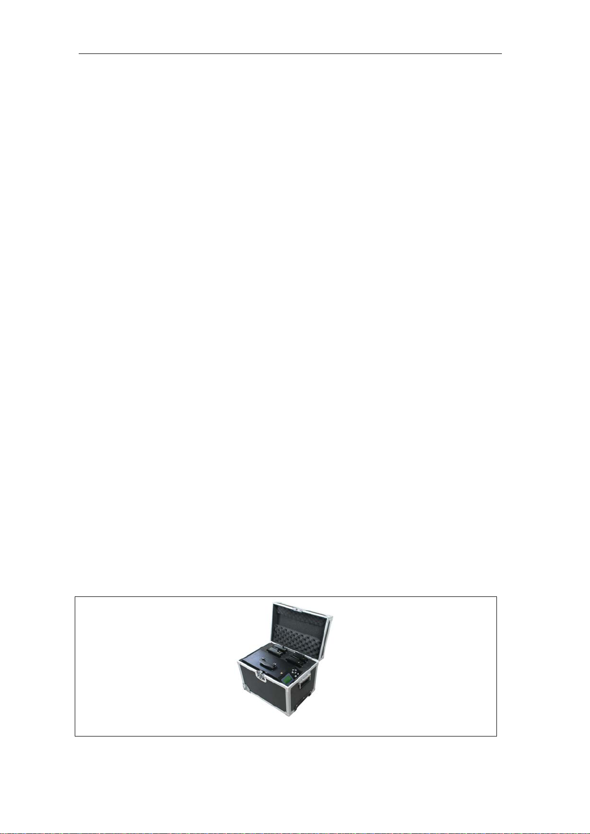
1.1 Accessories............................................................................................................................4
1.2 Safety Information................................................................................................................5
1.3 Operating Precautions.........................................................................................................6
2. OVERVIEW.........................................................................................................................7
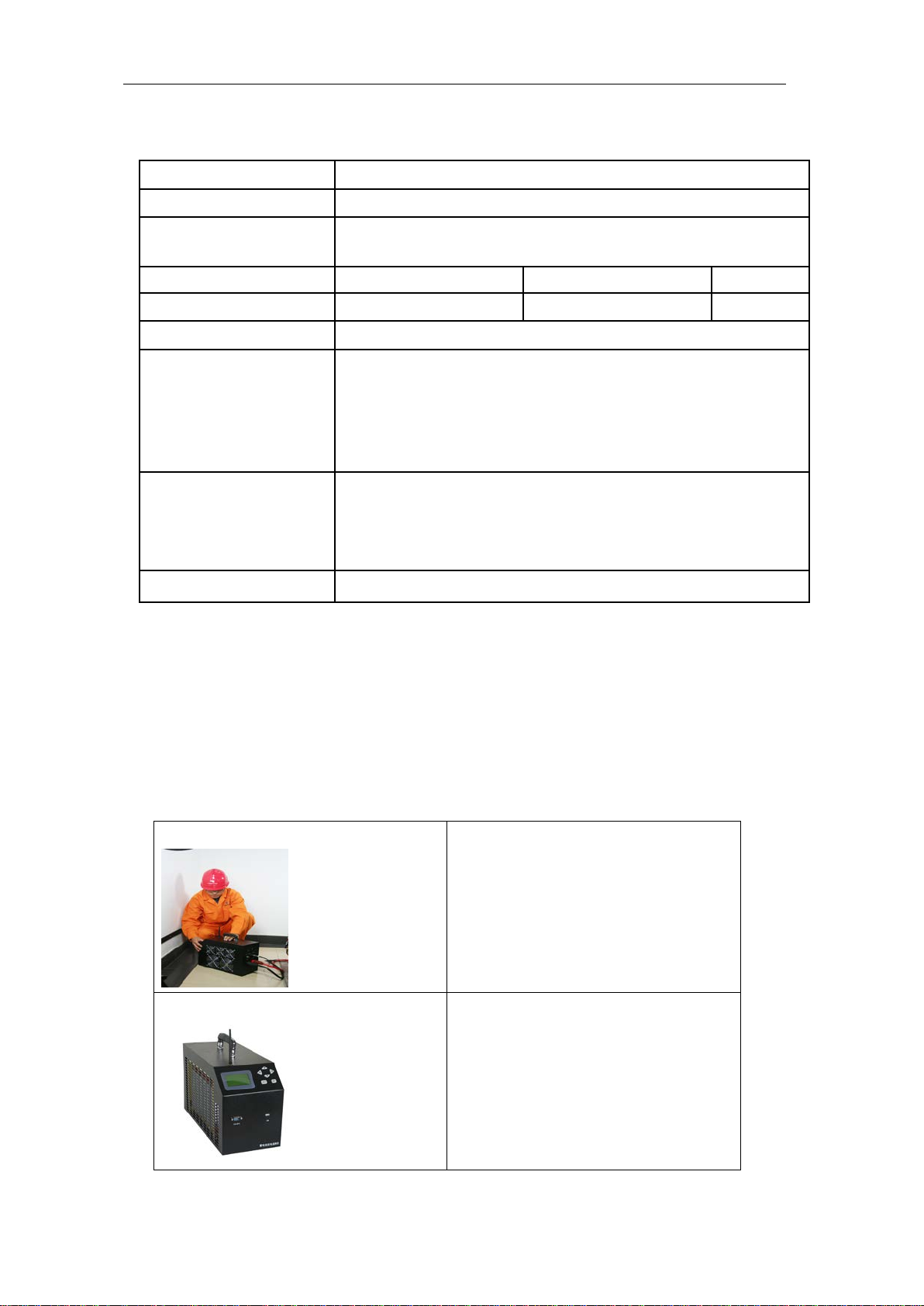
2.1 About LB 3980........................................................................................................................7
2.2 Display and Keypad .............................................................................................................8
2.3 Features...................................................................................................................................8
2.4 Specification .......................................................................................................................9
2.5 Measurement Flowchart......................................................................................................9
2.6 Definition of Abbreviation.................................................................................................10
3. MEASUREMENT PREPARATION...................................................................................10
3.1 Connection...........................................................................................................................11
3.1.1 Check Conditions........................................................................................................11
3.1.2 Connection of Cables.................................................................................................11
3.1.3 Connect with DAC.......................................................................................................13
3.1.4 Connect with Computer.............................................................................................17
3.2 Disconnection of Cables...................................................................................................18
3.3 Power On...............................................................................................................................18
4. MEASUREMENT..............................................................................................................18
4.1 Battery String Discharge...................................................................................................18
4.1.1 Discharge Test..............................................................................................................19
4.1.2 Discharge for Strings in Parallel Connection.......................................................22
4.1.3 Continued Discharge..................................................................................................23
4.1.4 Parallel Load Test........................................................................................................23
4.2 Other Tests ...........................................................................................................................25
4.2.1 Assistant Discharge....................................................................................................25
4.2.2 External test..................................................................................................................26
4.2.3 Charge Monitor.............................................................................................................27
4.3 Data Management...............................................................................................................28
4.3.1 Read Data Results.......................................................................................................29
4.3.2 Load to USB drive .......................................................................................................29
4.3.3 Delete Data Results.....................................................................................................29
4.3.4 Data Format...................................................................................................................30
4.4 System Management..........................................................................................................30
4.4.1 Time Setting..................................................................................................................30
4.4.2 Parameter Management.............................................................................................30
4.4.3 Function Setting...........................................................................................................33
4.5 Firmware Update.................................................................................................................34

3
5. SERVICE AND MAINTENANCE......................................................................................34
5.1 Cleaning ................................................................................................................................34
5.2 Storage ..................................................................................................................................34
5.3 Trouble-shooting.................................................................................................................35

4
1. INTRODUCTION
This Users Manual gives full information on how to use LB 3980 Battery Load Bank safely
and effectively. It applies to all LB 3980 models. Please read the manual carefully so as to
obtain maximum performance of the load bank and its accessories.
Warning: Read this manual completely before connecting and powering on the load bank to
avoid possible damage caused by improper use of this instrument.
1.1 Accessories
After receiving the LB 3980 unit, please ensure that no damage occurred during
transportation. Upon any damage or failure of operation based on this instrument, please
contact your supplier immediately. And make sure you have each items below:
♦LB 3980 main unit (1)
♦Carrying Case (1)
♦Data Acquisition Case (DAC) *
♦Data Acquisition Leads *
♦Antenna
♦Data Communication Terminal (1) *
♦USB-RS232 converter (1) *
♦USB drive (1)
♦Load Cables (1 black and 1 red)
♦Voltage test lead with two clamps (1)
♦AC Power Cord (1)
♦Users Manual (1)
♦Serial port cable (1,optional)
♦Current clamp (1, optional)
♦Grounding line (1)
NOTE:
1) Amount of Accessories marked with “*” may vary based on different LB 3980 models.
Please confirm with your supplier before each order.
2) DAC (Data Acquisition Case) is optional for data logging of each cell in LB 3980 series
load banks, amount of DAC and DAC serial cables may vary in different models. In
some basic load unit, there is no DAC and relevant cables. For detailed connection,
please refer to 3.1.3 Connect with DAC.
LB 3980 with Carrying Case*

5
Red Load Cable
Black Load Cable
Voltage test lead with two
clamps
DAC serial cable, 7-lead
(Optional with DAC)
DAC serial cable, 3-lead
(Optional with DAC)
Antenna
(for main body)
User Manual
Grounding line
USB drive
Current clamp
(optional )
AC220 Power Cord
DAC
(Optional)
*NOTE: For convenient transportation, models with size of XL or bigger will be made with
rolling wheel at main unit bottom and packed with wooden case instead of carrying case.
For detailed configuration, please refer to 2.4 Specification.
1.2 Safety Information
When you read this user manual, please carefully observe all warnings, precautions and
instructions for effective operation of LB 3980.
WARNING: Servicing described in this manual is to be done only by qualified personnel. To
avoid electrical shock, do not service the instrument unless you are qualified enough under
LB’s instruction.
DANGER
Safety testing has been done on this instrument thoroughly
before shipment. However, mishandling during use could result
in injury or other bad consequences, as well as damage to the
instrument. Make sure that you understand the instructions and

6
precautions in the manual before use. We disclaim any
responsibility for accidents or injuries not resulted directly from
instrument defects.
Safety Symbols
Description of symbols used in this manual.
WARNING Indicates correct operation to prevent a significant hazard that
could result in serious injury or other bad consequences to
users or the product.
NOTE Indicates advisory items related to perfor
mance or correct
operation of the instrument.
1.3 Operating Precautions
WARNING:
♦The electrical voltage and current used in battery testing is potentially lethal.
♦Ensure that the AC supply is isolated and any battery under test is disconnected before
attempting any cleaning or maintenance of LB 3980.
♦Do not connect or disconnect any of the cables unless the circuit breaker is turned off.
♦Connection and disconnection procedures are extremely important. Be sure to follow
the instructions faithfully.
♦Do not touch conducting parts of the load cables or the voltage cables when they are
connected to LB 3980.
♦Explosion risk when using LB 3980 (all models)
♦When a lead acid battery is charged or discharged i.e. when there is a current flow
through the battery it is always a risk that the battery can explode.
♦For new open (vented) batteries the risk is medium to low but in old VRLA (sealed)
batteries the risk is medium to high.
♦If there is a bad connection inside the battery and there is a current flow - the
connection will burn off and there will be an arc, which will ignite the oxyhydrogen gas
in the battery.
♦To minimize the risk for personnel injuries: Always place LB 3980 as far away from the
battery as possible - use long load cables and do not stand close to a battery during
charge or discharge.
♦Too high discharge current applied on a battery can cause the battery to explode or get
over-heated. And may also over-wear the batteries. Be sure to not set too high current.
♦If the external current measurement is interrupted or giving false values during the test,
the current will rise to a higher level than the set value before the test is shut down. If
the battery is too small for this current or in a bad condition - it may explode.
♦If you see any spark from batteries, testing cables or LB 3980 main body, please switch
off the unit and disconnect all cables for further inspection.
IMPORTANT:
To use LB 3980 efficiently and avoid electrical shock, fire or any damage to the LB 3980 or

7
its accessories, please do read these precautions carefully before using LB 3980:
♦Except as explained in this manual, do not attempt to service this equipment yourself.
♦To avoid frequency interference, please do not run two LB 3980 simultaneously in the
same location within 100 meters if it is not parallel connection. If you really have to,
please contact LB for presetting.
♦Before use, check to see if the nominal voltage ranges on the LB 3980 matches the
batteries that you are going to test. Do not apply LB 3980 of lower voltage in higher
voltage. For example, if LB 3980 nominal voltage is 48V, do not connect the unit with
batteries of 220V. Otherwise, some parts inside LB 3980 main body may get damaged.
♦Do not operate the LB 3980 around explosive gas or vapor.
♦Use only insulated load cables and test leads supplied with the load bank.
♦Before use, please inspect the load bank, load cables, test leads and accessories for
mechanical damage and replace them when they are damaged. Pay special attention
to the insulation surrounding the connectors.
♦If you have more than one LB 3980, please use them separately, do not mix them up.
Their accessories may not compromise with each other.
♦Remove all clamps, test leads and accessories that are not in use.
♦Make sure that the mains voltage and frequency fit the local AC power supply. Do not
apply the unit to voltages that are above the rated mains of the instrument.
♦Ensure that the equipment is provided with adequate ventilation. Do not block
equipment ventilation openings.
♦Proper installation is essential to the correct functioning of your analyzing software CD.
If you have any questions about installation, please contact your supplier for
assistance.
♦After discharging batteries for some hours, please keep the main body powered on for
at least 10 minutes. This will help cool down the resistors and other electronics inside
the main body and prevent it from over wearing.
♦If you need to discharge the next battery string right after the first string, please wait for
at least 30 minutes to let the unit cool down also.
2. OVERVIEW
2.1 About LB 3980
LB 3980 series Battery Load Bank are for battery discharge experiment, capacity test,
battery string maintenance, project checkup and acceptance, and DC power load test. For
battery maintenance, it is periodic examination (e.g. once a year). It is used to judge the
capacity of cells to see whether cells are weak to remove or renew. Users judge its capacity
by the way of discharge in one string or more strings.
The wireless communication technology enables it continuously monitor and display the
real-time discharging process of all individual cells via the monitoring terminal.
The measurement data can be read on the instrument screen directly. It can also be
uploaded to a personal computer via a USB driver. With the analyzing software, you could
have an all-rounded analyzing for the testing result and status of batteries.

8
2.2 Display and Keypad
The 6-button keypad enables you for quick navigation through the screen display or menu.
Fig.2.2. Keys Operation
Keys
Functions
▼▲Move up and down to highlight the selecting options
◄►1. Change the numbers
2. Move back and forth to highlight the selecting
options
Confirm the selection or number input
Return to the previous menu
2.3 Features
♦Rugged, compact and portable unit with carrying case
♦Wireless communication for convenient discharge monitoring in PC
♦It sets 4 conditions for auto shut-down of discharge:
discharge time, discharged capacity, cell cut-off voltage and total cut-off voltage
♦Continued discharge available when certain cells voltage reach cut-off value
♦Parallel connection of two units for mass discharge
♦Real-time display of voltage for each cell
♦Accurate data results and vivid waveforms
♦Powerful management system for data analyzing
♦Auto sorting for lag-out batteries during discharging
♦OptionalAC & DC power supply modes for different needs
♦Integrated functions for displaying, controlling and discharging
♦Safe circuits avoids damage to battery when testing
♦Direct USB drive for convenient data transfer to PC
♦Warning info, dynamic discharge and static discharge data auto-saving
♦It covers different types of batteries for a wide range of discharging like 24V, 48V,
110V, 220V and 380V in different models
ENT
ESC

9
2.4 Specification
Power Supply
AC 220V/110V or DC (from battery, optional), 50/60Hz
Discharging Current Accuracy: 1% Resolution: 0.1Aor 0.5%
Discharge voltage range 48V: 10-55.2V 110V: 10V-126.5V*
220V: 10-253V 380V: 10-437V
Voltage Accuracy 0.5% Sampling Interval 5s--1min
LCD Display 128*64 pixel Communication USB
Temperature
0℃~40℃5%~90% Relative humidity
CE marking
EMC standard:
EN55022:2006
EN55024:1998+A1:2001+A2:2003
EN61000-3-2: 2006
EN61000-3-3:1995+A1:2001+A2:2005
Dimension (main unit)*
400*177*280 mm (Size: S)
520*202*355 mm (Size: M)
555*225*435 mm (Size: L)
603*400*740 mm (Size: XL)
Weight (main unit)* 11kg(S) 16kg(M) 21Kg (L) 43Kg (XL)
NOTE*:
1). In some countries, 110VDC is replaced by 125VDC with range of 10-143V, and 220V is
replaced by 240V (10-288V).
2). Dimension and weight depend on different models; more customized models may differ
in some aspects.
2.5 Measurement Flowchart
The measurement workflow is described as below
Measurement Preparation
1. Wear necessary protective
clothing
2. Connect the
AC power cord (if
power supply is from AC)
3. Connect the testing leads
4. Turn the power on
Start Measurement
1. Select measuring mode
2. Read displaying results

10
Ending of Measurement
1. Disconnect the test leads from the
subject of measurement
2. Turn off the power
3. Disconnect the power cord
Data uploading
Measurement of data
1. Us a USB drive to load the testing
data and transfer the data to PC
2. Data management on PC
WARNING: There are high voltage and current in cells and the load bank components. Only
qualified personnel can perform all the measuring procedure. Pay special attention to
precautions of electrical and chemical safety when removing cells, installing cells,
connecting leads and making measurements.
2.6 Definition of Abbreviation
Below are the definitions of abbreviated words used in LB 3980 software menu:
Abbreviation
Full name
Abbreviation
Full name
avg
average
I
current
DIS discharge Paral Parallel
C capacity param parameter
calib calibration strg/stg string
Case acquisition case syst system
CHG charge T time
comm communication tot total
EX
exit
U
voltage
3. MEASUREMENT PREPARATION
This section describes how to connect all the testing leads and cables in correct way and
sequence. It is very important for the whole process of operation. For the safety of
equipments and operators, please read it carefully.

11
3.1 Connection
3.1.1 Check Conditions
Before any connection, make sure that:
1). The battery strings are not working and cut off from power supply.
2). There is enough space for testing. Do not test the unit around explosive gas or vapor.
3). The nominal voltage of the load bank matches that of the battery strings.
3.1.2 Connection of Cables
IMPORTANT: Power supply and control on-off (circuit breaker) should be turned off before
all wire connections. To ensure the safety, please turn on the control on-off ONLY when all
the other connections are finished.
All switches and cable sockets are at the back of the main unit. Pleases see blow for the
back panel of LB 3980.
Fig 3.1.2
A. Connection of load cables
Connect one end (round socket) of the black load cable with the black port of the load
bank and the other end (with clamp) with the negative pole of battery string.
Connect one end of the red load cable with the red port of the load bank and the other
end with the positive pole of battery string.
WARNING: Make sure they are correctly and tightly connected to avoid electrical fire
and short circuit. The black and red load cables should be firstly connected with load bank
main unit with power off, and then with batteries. If you firstly connect them with batteries
and the other two ends accidentally get connected with each other, there will be return
circuit. Thus load cables and their clamps may get burned.
In the same way, after the testing is done, please first turn off the power, disconnect the load
cables from batteries and then disconnect them from LB 3980 main unit.

12
Fig. 3.1.2.A1 Fig. 3.1.2.A2 Fig. 3.1.2.C
B. Connection of voltage testing lead
Connect one end (round connector) of the voltage testing lead to the voltage socket of the
LB 3980, and the other two clamps with two poles of battery string. The red clamp is
connected with the positive pole and the black with the negative of battery string.
C. Connect the antenna to the antenna socket of the load bank like Fig. 3.1.2.C. LB only has
one type of antenna for main unit, DAC and communication terminal.
D. When power supply is from AC, connect the load bank to an appropriate AC power
source with the AC power cord. And turn the power switch at the back of load bank to AC
220 (or 110V mains). When power supply is from batteries, turn the mains switch to DC.
In that case, power will be supplied via the two load cables.
E. In the following 3 auxiliary testing functions, you will need a current clamp:
1) External discharge.
In this function, LB 3980 only serves the function to display the voltage (by DAC)
and current values of external load.
If you do not need to test current value of external load, current clamp is not needed.
2) Reparation discharge (assistant discharge)
For example, if external loads discharge 10Amps from the batteries and but your target
is to discharge 25Amps, you could use LB 3980 reparation discharge to handle the rest
15Amps.
A current clamp is needed to monitor the external current value. If external value is
changed (e.g. 13Amps), reparation discharge value will change (12Amps) accordingly
so as to make total discharge current (25Amps) unchanged.
Current clamp range is accordant with external load.
3) Charge monitor
LB 3980 also only serves the function to display the voltage (by DAC) and current
values as the batteries are charged. If you do not need to monitor current value or you
have other way to monitor current value, then optional current clamp not needed.
So no matter which way it takes, current clamp range should be accordant with external
loads or chargers. For details, please refer to 4.2 Other Test.
WARNING: Make sure the black load cable is connected to the negative pole, and the
red one to the positive, otherwise it may cause significant damage to the load bank.

13
Other way of load cable connection:
In some high power model of load bank, clamp of load cable is bigger and harder to open.
Therefore, in these models of load bank package, the clamps are separated from cables like
Fig 3.1.2.1. For different situation, you could use load cable connected directly with battery
posts like Fig. 3.1.2.2. Or you could fix the clamp on load cable and connect with battery like
Fig 3.1.2.3.
Fig 3.1.2.1
Fig 3.1.2.2 Fig. 3.1.2.3
3.1.3 Connect with DAC
Reminder: Below are introduction of DAC and instruction for its connection with batteries.
This info is for the new DAC with insulation-protected case only. For introduction and
connection ways of old model (black metal case) of DAC, please refer to previous version.

14
Fig.3.1.3.1 DAC Fig. 3.1.3.2 Magnetic bolts for instant
Attachment to metal bars or cases
About DAC
The DAC is optional to LB 3980. It is used for data logging of voltage for each cell. With
built-in antenna, it could have wireless communication with LB 3980 main body and PC
software.
If your model of LB 3980 comes with DAC and relevant serial cables, please see below for
instruction. If there is no DAC for your model, voltage of each cell will not display either in
the main unit screen or the PC software during discharge.
Each DAC has 2 serial ports for connection with DAC serial cables. These 2 ports are
labeled with 1 and 2 which are connected with red (#1) and black (#2) connectors of DAC
cable. They are for connecting with different series of batteries in a string. For detailed way
of connection, please refer to the text below.
About DAC leads
LB 3980 also has two kinds of data acquisition leads 7-lead and 3-lead
All standard models of LB 3980 battery load bank could test batteries of 2V, 6V and 12V. For
different battery types, we have two kinds of data acquisition cable: 7-lead and 3-lead.
Please use the 7-lead cable (Fig.3.1.3.3) for testing 2V batteries. And use the 3-lead cable
(Fig.3.1.3.4) for 6V or 12V batteries. In these LB 3980 units, both 7-lead and 3-lead use the
same DAC.
NOTE: In optional models of LB 3980 battery load bank which test 1.2V, ways of DAC
connection with battery are same with that of 2V batteries.
Please see pictures below for further illustration of data acquisition leads:
Fig.3.1.3.3
Fig.3.1.3.4
7-lead, 1 black and 6 red
For testing 2V batteries
One cable is connected with 6 cells
One DAC is connected with 12 cells
3-lead, 1 black and 2 red
For testing 6V or 12V
One cable is connected with 2 cells
Once DAC is connected with 4 cells
NOTE:
a) All LB 3980 models have the same type of DAC (may be different in amount).
However, all DACs have been programmed with different serial numbers to match
specific LB 3980 unit. Therefore, for DAC connection with batteries, use them in
the order of DAC 1, DAC 2 and so forth.
b) If you only need the LB 3980 as a load without voltage logging for each cell, then it

15
is no need to connect DAC or relevant cables. You will only need to set the total
cutoff voltage, discharge time and capacity. In that case, cell number should be set
as 0. For detailed settings, please check 4.1.1 Discharge Test.
Way of connection
1). Connection of DAC and leads are as below:
Fig.3.1.3.4
Fig.3.1.3.5
Connection with 2 serial cables of 7-lead
Connection with 2 serial cables of 3-lead
2). Connection of DAC leads and batteries
Below are correct ways of connections for DAC leads with different batteries
A. Connections for 3-lead cable will be as below:
Make sure that DACs are always connected with battery string beginning from negative
pole, no matter the whole string begins from the negative pole or possible pole.
Hereafter, “0” below indicates the black lead which is connected with negative pole of
batteries. Every DAC lead is labeled with serial numbers (0, 1, 2 …) below. They have
nothing to do with serial numbers marked on the batteries. However, DAC leads should
be connected with batteries in sequences of 0, 1, 2 and so forth.
NOTE : 1# below indicates serial port labeled with “1” on DAC. 2# means “2” labeled on
DAC. This is same to all the other ways of DAC connection described below.
Fig.3.1.3.A
B. Connections for 7-lead cable will be as below:

16
Fig.3.1.3.B
C. If there is only one DAC and cell numbers are less than what one DAC can measure, we
have two situations:
1). If you only need one DAC serial cable for all cells connection, then just use one serial
cable (connected with serial port 1#). See examples in Fig.3.1.3.C1 and Fig.3.1.3.C3.
2). If you need 2 serial cables for cell connection but have spare DAC leads, then connect
all of the spare leads (on port 2#) with the last cell. See examples Fig.3.1.3.C2 and
Fig.3.1.3.C4.
Fig.3.1.3.C1, cell type: 12V Fig.3.1.3.C2, cell type: 12V
Fig.3.1.3.C3, cell type: 4V Fig.3.1.3.C4, cell type: 4V
D. For more than one DACs (e.g. cell type is 12V), connection is like below:
DAC N -- -- -- -- -- DAC 2 DAC1
(The last DAC) Fig. 3.1.3.D
E. If there are more than one DAC and with spare leads (the last DAC), connection of the

17
last DAC will be: the last testing lead M# (labeled with highest serial number) will be
connected with positive pole of the last (N#) cell; and testing lead (M-1) # will be
connected with positive pole of (N-1) # cell, so and so forth until all the spare leads are
well connected. Cell type is 12V in the example below:
DAC N DAC(N-1)-- ---- DAC 2 DAC 1
(The last DAC)Fig. 3.1.3.E
DAC is powered by batteries that are connected via different DAC leads. When you see the
indicating light on DAC blinks, the DAC gets full power supply then. If you do not see
indicating light blinks when connecting the first DAC lead, continue to finish connection with
other leads.
3.1.4 Connect with Computer
With the LB DataView Software, you could have a real-time monitoring during the whole
process of battery discharging and even battery charging. Flowchart of discharge monitor is
as below:
1. Install the software driver for USB-Rs232 converter in your PC. For installation
instruction, please check its manual separately.
2. Connect the USB-Rs232 converter with PC and remember the com port number.
3. Connect data communication terminal with USB-Rs232 converter and switch on the
terminal.
4. Start discharging, test com port and start online monitor. For software operation on PC,
please refer to 6.3.1 Real-time Monitor.
Fig 3.1.4 connection of com terminal with PC

18
3.2 Disconnection of Cables
After battery discharge is finished, please keep the main body powered on for at least 10
minutes. This will help cool down the resistors and other electronics inside the main body
and prevent it from over wearing. This is pretty important to use the load bank effectively.
To ensure security of equipment and operator, please disconnect all cables in the following
sequence:
1) Turn off the power switch
2) Turn off the control on/off
3) Disconnect power cord from mains
4) Disconnect load cables first from batteries and then from LB 3980. The two load cables
should be removed one after one. This is important for security.
5) Disconnect the voltage cable first from battery and then from LB 3980 load bank.
6) Disconnect the serial cable for parallel connect (if any).
7) Remove current clamp (if any) from LB 3980.
3.3 Power On
After all cables are well connected, LB 3980 is ready for operation. Turn on power switch
and control on/off on LB 3980, the screen will display info of configuration and software
version like below:
Fig. 3.3
NOTE: Above figure is only for reference. Specification and version information will differ
based on different configuration.
The following main menu will show after initialization of about 10 seconds:
Fig.3.3.1
4. MEASUREMENT
4.1 Battery String Discharge
Press the keys ↑/↓ to highlight [Discharge]and press ENT to the following step

19
Fig.4.1
4.1.1 Discharge Test
This is basic function for battery discharge by LB 3980; it is different from external discharge
by other load. With optional DAC and LB DataView software, you could have a real-time
monitoring for discharge in your PC. For detailed way of operation, please refer to 6.3.1
Real-time Monitor.
To start operation in LB 3980 main unit, select [DIS test] under the menu [Battery DIS] and
press ENT:
Fig.4.1.1
In the menu [DIS test], press ←/→ arrow keys for number setting, use ↑ and ↓ to move up
and down.
There are 9 options under [DIS test]including: [Strg type](nominal voltage, optional
among 24V, 48V, 110V, 220V and 380V. Based on different LB 3980 models, you have
different options), [Cell type] (1.2V, 2V, 6V or 12V), [Cell No.](Indicates tested cells
quantity. If there is no connection with DAC, set is as 0), [DIS I](indicates working current),
[Tot end U ](indicates the total cut-off/threshold voltage for the battery string), [Cell end U]
(indicates the cut-off voltage for the individual cell), [DIS C](indicates the discharged
capacity of battery string), [DIS Time](indicates the duration for this test.), [#1 cell polar]
(indicates the beginning polarity of first cell in the whole string),
About first cell polarity
About first cell polarity setting, please see below:
As we mentioned above, DAC is always connected with battery string beginning from
negative pole, no matter the whole string begins from the negative pole or possible pole.
So for DAC connection in different countries, there are 2 situations as below:
1) If polarity of first cell in string is negative (-), then you should select negative (-) in
menu. And NO.1 DAC is connected from the first cell.
2) If polarity of first cell in string is positive (+), then the last polarity of the string will be
negative (-). In that case, you should connect the DAC 1 with string, beginning from
the last cell. Cell polar is set as positive (+). Then cell No. 1 is the actual reading
shown on the LB 3980 LCD display and so forth
If DAC connection is correct but setting of first cell polarity is incorrect, voltage value
displayed in LB 3980 LCD screen and PC software will be reversed. In another word,
voltage value of first cell will become value of the last cell, second will become second last
and so forth.
Four conditions for discharge auto-stop:

20
They are: Total end voltage, cell end voltage, discharged capacity and discharge time.
The discharge process will stop once any one of these 4 conditions reaches its setting value
(threshold).
Setting of cutoff voltage:
Setting of cutoff voltage is for the protection of cell. Correct setting of cutoff voltage value will
prevent the cell from over discharge and thus avoid damage to the cell. Following settings
are for your reference:
1.2V cell—Cutoff discharge voltage: 1.08V;
2V cell---Cutoff discharge voltage: 1.8 V;
12V cell---Cutoff discharge voltage: 10.8 V;
After setting for all parameters, press ENT to continue:
Fig.4.1.1.1
Select [Confirm] and press ENT to execute the operation. To use LB software for discharge
monitor, you have to test com port after you see the following screen.
It will need 1 minute before the discharge begins as screens below:
Fig.4.1.1.2 Fig.4.1.1.3
NOTE: If the internal memory space is not enough, the following screen will pop up:
Fig.4.1.1.4
Press any key to exit, go back to data managementmenu, download the previous records to
a USB drive, and delete the data to continue discharging process.
After entering discharge screen, it needs 1 minute to check each cell voltage before
discharge starts. Thus testing personnel knows the situation of the string. After discharge
ends, there is 1 minute left to test the recovering of voltage
In discharge screen (Fig.4.1.1.3), [DIS C] indicates string capacity discharged from
batteries. [U] indicates total voltage of string. [I] indicates actual discharged current. [Min
cell] indicates the cell with lowest voltage during discharging. In example of Fig.4.1.1.3, No.
1 cell has lowest voltage, 2.001V.
NOTE: Descriptions in this part assume that your LB 3980 is operated with DAC. If you do
not have data logger (DAC) for your LB 3980 model, voltage of each cell will not display.
Table of contents
Other Pite Test Equipment manuals
Popular Test Equipment manuals by other brands

DEZEGA
DEZEGA PGS-2 user manual

Compliance West
Compliance West HT-2000PR instruction manual

Brüel & Kjær
Brüel & Kjær 1019 instruction & application

CellScale
CellScale UniVert user manual

Agilent Technologies
Agilent Technologies AuroraPresto user guide

MULTI MEASURING INSTRUMENTS
MULTI MEASURING INSTRUMENTS 230+ instruction manual