manuals.online logo
Brands
  1. Home
  2. •
  3. Brands
  4. •
  5. Pittway
  6. •
  7. Control Unit
  8. •
  9. Pittway System Sensor MOD400R User manual

Pittway System Sensor MOD400R User manual

Models Available
MOD400R Field Sensitivity Test Module
MOD400R
Field Sensitivity
Test Module
© System Sensor 8/98 This document is not intended to be used for installation purposes. A05-193-02
APPROVED
A Division of Pittway
3825 Ohio Avenue, St. Charles, IL 60174
1-800-SENSOR2 (736-7672), Fax 630-377-6495
http://www.systemsensor.com
MOD400R Specifications
Dimensions: 41/2″×31/8″×11/2″
(11.43 cm ×7.93 cm ×3.81 cm)
Shipping Weight: 8.4 oz (238 gm)
Test Capability: System Sensor 100, 200, 300,
400, 500 Series Detectors
System Sensor DH100, DH200,
DH400, DH500 series duct
smoke detectors
Battery: 9 V alkaline (1 year life)
Features
• Compatible with all System Sensor direct wire and plug-
in smoke detectors (100, 200, 300, 400, and 500 series),
or System Sensor’s DH100, DH200, DH400 and DH500
series duct smoke detectors, ionization or
photoelectronic
• Fulfills NFPA 72 requirement for field sensitivity testing
• Interfaces with standard DC voltmeter or multimeter
• Low battery diagnostic
–When connected to a voltmeter, the MOD400R
monitors its own battery voltage
• Quickly tests sensitivity of detectors without putting
system into alarm
The MOD400R Field Sensitivity Test Module is designed
to check the sensitivity of System Sensor’s 100, 200, 300,
400, and 500 Series conventional detectors or System
Sensor’s DH100, DH200, DH400 and DH500 series duct
smoke detectors, to fulfill the NFPA 72 requirement for
detector sensitivity testing.
The test module can be connected to any DC voltmeter
(meter movement of 10K ohms/v or greater) to obtain a
reading which correlates to the detector’s sensitivity range.
Page 2 A05-193-02
Testing and Maintenance
Test DetectorReinstall or
Replace Screen
Check Sensitivity Vacuum and/or Blow-Out
Screen and Chamber
Smoke Detector Maintenance
Nuisance alarms from smoke detectors can be caused by a
number of conditions, but one of the more prevalent is
lack of proper maintenance. Everyday dust, grime, and
moisture can render detectors ineffective or change
sensitivity levels.
Ease of Maintenance
NFPA 72 requires that all smoke detectors shall be visually
inspected in place at least semiannually to identify missing
detectors, detectors with impeded smoke entry,
abnormally dirty detectors, and detectors no longer
suitably located because of occupancy or structural
changes. The standard also goes on to say that a test shall
be performed annually to assure that each smoke detector
is operative and produces the intended response.
System Sensor detectors have been designed with these
requirements in mind. Detectors may be disassembled
quickly to allow convenient access to the special .020″
(0.5mm) mesh insect screen and chamber.
The screen should be removed and thoroughly cleaned
with a soft brush or vacuum to remove all loose and
excessive dirt buildup. Clean compressed air is
recommended to blow out any remaining debris on the
screen or in the sensing chamber.
Simple Testing
Test by pushing recessed
switch with any 0.1″maximum
diameter object
Photo unit can be tested
by inserting calibrated
test card and moving
it counterclockwise
into position.
NOTE:
Detector cover
removed
Once cleaned, the detectors must be reinstalled and tested
to insure proper operation of the system. All direct-wire
detectors are equipped with a recessed switch that can be
activated using any 0.1″maximum diameter object. When
the switch is activated, the LED on the detector should
light within 20 seconds to indicate alarm status. Plug-in
detectors (with separate base) incorporate the use of a
magnet test. The 400 Series photo can also be tested with
a calibrated test card. A special slot in the screen housing
allows the test card to be inserted into the chamber. The LED should indicate a latched
alarm condition after 20 seconds when the ALARM end of the card is used; no reaction should occur when tested with
the NO ALARM end.
These built-in test functions are designed to simulate a 3% per foot obscuration level on the ionization units and a
4% per foot obscuration on the photoelectronic units. This is more than sufficient to determine if the detector will
alarm, but is not an adequate way to test and verify a unit’s sensitivity as required by NFPA 72. Instead, use the
MOD400R Sensitivity Test Module to satisfy the NFPA requirement for testing sensitivity.
System Sensor Worldwide Manufacturing & Distribution
In Canada:
Telephone: 905-812-0767
Fax: 905-812-0771
In China:
Telephone: 852-2191-9003
Fax: 852-2736-6580
In the Far East:
Telephone: 852-2191-9003
Fax: 852-2736-6580
In India:
Telefax: 91-022-8202564
In Italy:
Telephone: 39-40-9490-111
Fax: 39-40-382137
In the United Kingdom:
Telephone: 44-1403-276500
Fax: 44-1403-276501

Other Pittway Control Unit manuals

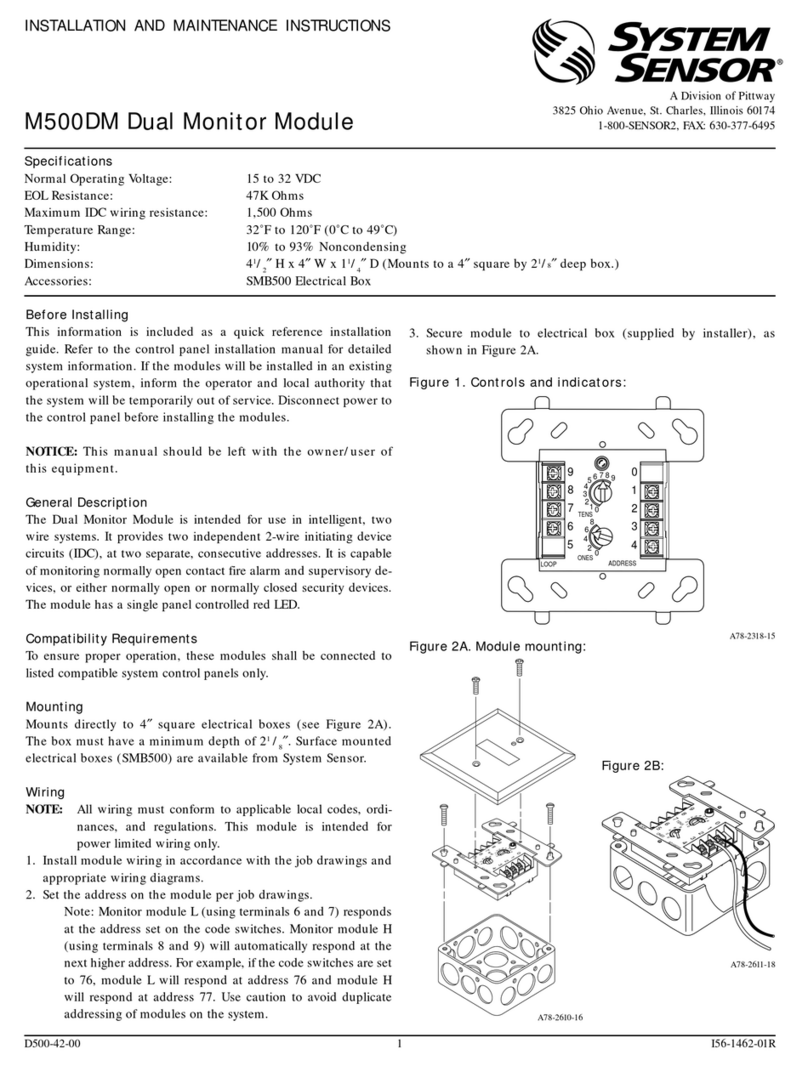
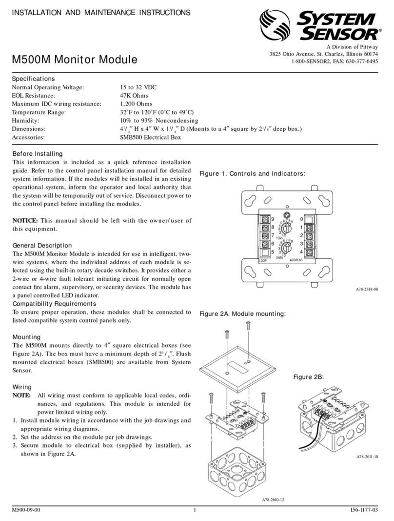
Pittway SYSTEM SENSOR M500DM User manual

Pittway

Pittway SYSTEM SENSOR M500DM User manual

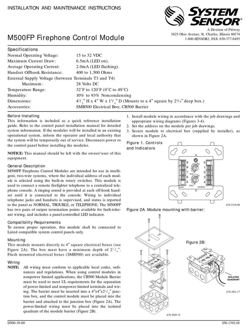
Pittway SYSTEM SENSOR M500FP User manual

Pittway

Pittway SYSTEM SENSOR M500FP User manual

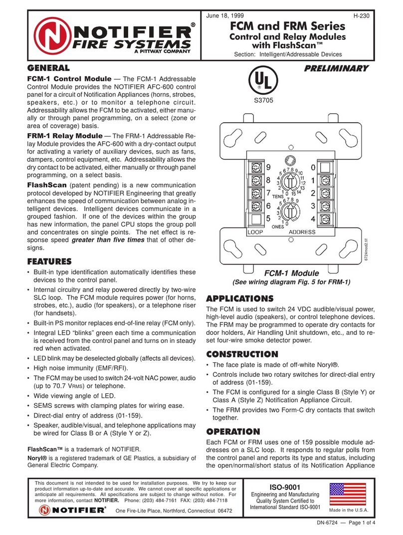
Pittway NOTIFIER FCM Series User manual

Pittway

Pittway NOTIFIER FCM Series User manual

Pittway SYSTEM SENSOR M500M User manual

Pittway

Pittway SYSTEM SENSOR M500M User manual

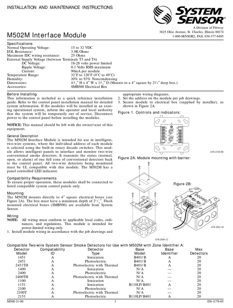
Pittway SYSTEM SENSOR M502M User manual

Pittway

Pittway SYSTEM SENSOR M502M User manual

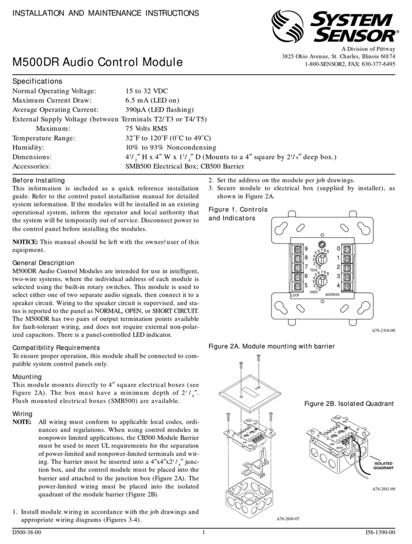
Pittway System Sensor M500DR User manual

Pittway

Pittway System Sensor M500DR User manual

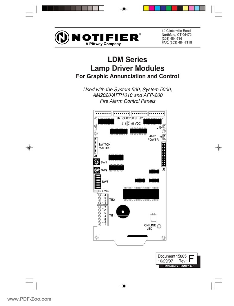
Pittway NOTIFIER LDM Series User manual

Pittway

Pittway NOTIFIER LDM Series User manual

Pittway NOTIFIER UZC-256 Installation manual

Pittway

Pittway NOTIFIER UZC-256 Installation manual

Pittway Fire-Lite Alarms MMF-300 User manual

Pittway

Pittway Fire-Lite Alarms MMF-300 User manual

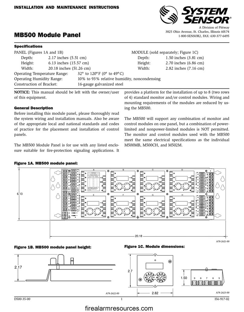
Pittway System Sensor MB500 User manual

Pittway

Pittway System Sensor MB500 User manual

Popular Control Unit manuals by other brands

Nibe PKM 05 installation instructions

Nibe

Nibe PKM 05 installation instructions

CARLO GAVAZZI Certus CM22D0A instruction manual

CARLO GAVAZZI

CARLO GAVAZZI Certus CM22D0A instruction manual

ETAS ES413.1 user guide

ETAS

ETAS ES413.1 user guide

Genmitsu Jinsoku LC-40 user manual

Genmitsu

Genmitsu Jinsoku LC-40 user manual

Lutron Electronics seeTouch guestroom solutions installation guide

Lutron Electronics

Lutron Electronics seeTouch guestroom solutions installation guide

Shelly Uni User and safety guidelines

Shelly

Shelly Uni User and safety guidelines

Bradley AST4 Operation and service guide

Bradley

Bradley AST4 Operation and service guide

Zenitel ZMK-1 installation manual

Zenitel

Zenitel ZMK-1 installation manual

BRUEL & KJAER 3015 Service manual

BRUEL & KJAER

BRUEL & KJAER 3015 Service manual

Valcom V-2001A Technical specifications

Valcom

Valcom V-2001A Technical specifications

Pololu Wixel user guide

Pololu

Pololu Wixel user guide

Z-Wave QUBINO FLUSH SHUTTER user manual

Z-Wave

Z-Wave QUBINO FLUSH SHUTTER user manual

Festo CPX-E- AO-U-I Series Instructions for use

Festo

Festo CPX-E- AO-U-I Series Instructions for use

Comeval UNIFLOW PP Series Installation, operating and maintenance manual

Comeval

Comeval UNIFLOW PP Series Installation, operating and maintenance manual

Siemens SIRIUS 3TK2834 operating instructions

Siemens

Siemens SIRIUS 3TK2834 operating instructions

Harvia Xenio WiFi CX1704XW manual

Harvia

Harvia Xenio WiFi CX1704XW manual

Wieland podis FCS 6 5 SI SA Installation instruction

Wieland

Wieland podis FCS 6 5 SI SA Installation instruction

ProSoft Technology InRax MVI71-DNPSNET user manual

ProSoft Technology

ProSoft Technology InRax MVI71-DNPSNET user manual

manuals.online logo
manuals.online logoBrands
  • About & Mission
  • Contact us
  • Privacy Policy
  • Terms and Conditions

Copyright 2025 Manuals.Online. All Rights Reserved.