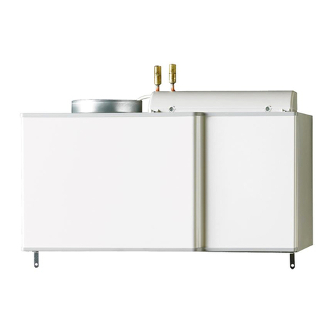
Nibe PKM 05 User manual

PKM 05
MAV 0751-3
PKM 05
031159
MONTERINGSANVISNING PASSIV KYLMODUL PKM 05
SE
MONTAGEANLEITUNG MODUL FÜR PASSIVES KÜHLEN PKM 05
DE
MONTAGEHANDLEIDING PASSIEVE KOELMODULE PKM 05
NL
INSTALLATION INSTRUCTIONS PASSIVE COOLING MODULE PKM 05
GB


1PKM 05
SE
Allmänt
PKM 05 gör det möjligt att erhålla passiv kyla från
berg-, grundvatten- eller ytjordkollektor. Vid användning
av ytjordkollektor kan markens beskaffenhet begränsa
möjligheten att utvinna passiv kyla.
PKM 05 är avsedd för golvsystem, vilket då både blir
kyl- och värmeavgivare. Kylan startas när utetempera-
turen överstiger inställd temperatur och regleras sedan
via vald kylkurva. För bästa komfort kan rumsgivare, RG
10 (tillbehör, Art nr: 018 433), användas. För att undvika
kondensutfällning ska lägsta tillåtna framledningstem-
peratur (ca 18 °C) väljas.
OBS! Kyldrift och varmvattenladdning kan ej köras sam-
tidigt.
Innehåll
1 x Håltagningsmall
1 x Rörsats FIGHTER 1240
1 x Bipackningssats PKM 05:
- 2 x Buntband
- 1 x Etikett
- 1 x Kabelband
- 1 x Kabelsats
- 1 x Kantskydd (0,1 m)
- 2 x Kopplingsplint 3-pol.
- 1 x Monteringsplåt
- 1 x Rak koppling ø28
- 9 x Skruv
- 1 x Stödhylsa ø28
- 1 x Stödhylsa ø22
- 2 x Vinkelkoppling ø28
- 1 x Vinkelkoppling ø28/22
MONTERINGSANVISNING
PKM 05
Till installatören
För FIGHTER 1240 monteras kylmodulen på sidan av
värmepumpen.
För FIGHTER 1140 monteras kylmodulen på väggen.
OBS! Se till att spänna alla kopplingar en extra gång,
både i och utanför PKM’en, efter att PKM är installerad
och monterad.
OBS! Använd inte rören som bärhandtag.
OBS! Medlevererade rör ska kondensisoleras.
OBS! Vid första uppstart måste PKM 05 (PKI) aktiveras
i meny 9.2.16 för att shuntventilen ska ställa sig i rätt
läge.
Måttskiss PKM 05
Tekniska data
PKM 05
Anslutning, varma sidan (mm) 28
Anslutning, kalla sidan (mm) 28
Höjd (exkl. rör) (mm) 330
Bredd (mm) 457
Djup (mm) 180
Vikt (kg) 9
Kyleffekt (kW) 3 – 6
Avsedd för värmepumpar (kW vid 0/35 °C) 5 – 10
Art nr 067 017
457
54 120
330
83 182
75
60
75

2PKM 05
SE
A Värmebärare retur (till PKM)
B Värmebärare retur (från PKM)
C Köldbärare in (till PKM)
D Köldbärare ut (från PKM)
E Shuntventil
Komponentplacering
Montering
PKM 05 kan monteras på både vänster respektive höger
sida på FIGHTER 1240 (se bild).
Bipackad konsol skruvas fast i hål uppborrade enligt
medskickad håltagningsmall eller enligt måttskiss nedan.
OBS! Borra försiktigt genom plåten för att undvika
skada på kärl eller annan utrustning.
Vid montage på vägg används den medlevererade upp-
hängningskonsolen, vilken först skruvas upp (enklast
används medskickad håltagningsmall).
OBS! Uppborrning av hål, uppfästning och placering på
vägg anpassas efter väggtyp och andra förhållanden på
plats.
Därefter monteras kylmodulen i konsolen. Kylmodulen
är nu till viss del skjutbar i sidled, vilket underlättar rörin-
stallation.
Röranslutning
Rör för anslutning till och montering på FIGHTER 1240
bipackas.
Rören ansluts enligt följande (se bild nedan och princips-
chema):
(B) ansluts till värmebärare retur på värmepumpen.■
Monteras PKM 05 på höger sida av värmepumpen
anpassas längden på röret.
(D) ansluts till köldbärare in på värmepumpen.■
(A) ansluts till retur från värmebärarsystemet.■
(C) ansluts till inkommande från kollektorn.■
260
128265
260 100 100
265 128
4x Ø4,5 4x Ø4,5
LEFT RIGHT
260
128265
260 100 100
265 128
4x Ø4,5 4x Ø4,5
LEFT RIGHT
Vänster
Vänster
FIGHTER 1240
Stödhylsa ø22
Höger
Höger
BE
AC D
Stödhylsa ø28
Shuntventilen är satt i kyldrift från fabrik.
OBS!

3PKM 05
SE
Principschema
Utföres enligt nedanstående schema. Rörinstallation
skall utföras så att vibrationen ej överförs från värme-
pumpen till kylmodulen via rörledningarna och vidare.
EXP
SÄV
SÄV
A
B
C
E
D
NK
AV
KB-in
KB-ut
FIGHTER 1240
BK/JK
VVB/ACK
PKM
SV
AV
EXP
SÄV
SÄV
A
B
C
E
D
NK
AV
KB-in
KB-ut
FIGHTER 1240
BK/JK
VVB/ACK
PKM
SV
AV
AV Avstängningsventil
BK/JK Bergkollektor/Jordkollektor
EXP Expansionskärl
FG Framledningsgivare
KB-in Köldbärare in
KB-ut Köldbärare ut
NK Nivåkärl
SV Shuntventil
SÄV Säkerhetsventil
VVB/ACK Ackumulator med varmvattenberedare

4PKM 05
SE
Elinstallation FIGHTER 1140
Kablage från PKM 05 kapas till rätt längd och anslutes
till FIGHTER 1140 enligt följande:
De lösa ändarna i kablaget monteras enligt följande (se
elschema och bild):
- Röd ledare anslutes till -X6:20.
- Svart ledare anslutes till -X6:21.
- Blå ledare anslutes till -X6:22.
- Den gröna respektive vita ledaren används ej, utan
isoleras.
- Gul/grön ledare anslutes till –X6:6.
LEK
LEK
F1120-30 mitsu
29 132
2
102
100
101
660
9
26
61
97
10
67
25
83
69
164
165
-X6
Reläkort
Shuntmotor
All elektrisk inkoppling skall ske av behörig
elektriker.
Elektrisk installation och ledningsdragning
skall utföras enligt gällande bestämmelser.
OBS!

5PKM 05
SE
Elinstallation FIGHTER 1240
Kablage från PKM 05 kapas till rätt längd och anslutes
till FIGHTER 1240 enligt följande:
1. Montera kantskyddet på den vassa kanten, se bild till
höger.
2. Montera kopplingsplintar, etikett och dragavlastare
på plåten. Skruva fast plåten med de tre medföljande
M5 självgängande torxskruvarna, se bild nedan.
3. Tryck fast den 7-poliga kantkontakten med nollnum-
mer 0101, 0102, 0103 och 0105 på reläkortet –E29
enligt elschema brevid (OBS! Notera spårningen i
kantkontakten). Montera sedan de lösa ändarna en-
ligt följande:
- Svart ledare med nollnummer 0101 till fjäderplint
–X6:1.
- Brun ledare med nollnummer 0102 till fjäderplint
–X6:2.
- Blå ledare med nollnummer 0103 till fjäderplint
–X6:3.
4. De övriga enskilda ledarna anslutes enligt följande:
- Gul/grön ledare med nollnummer 0104 till ledig
anslutning på jordflatstiftet –PE3 se bild och i fjä-
derplinten –X6:6.
5. Ledare från shuntmotor anslutes enligt följande:
- Röd ledare till fjäderplinten –X6:1
- Svart ledare till fjäderplinten –X6:2
- Blå ledare till fjäderplinten –X6:3
- Gul/grön ledare till fjäderplinten –X6:6
- Grön ledare till fjäderplinten –X6:7
- Vit ledare till fjäderplinten –X6:8
Reläkort
Shuntmotor
Elkoppling
M5, självgängade
torxskruvar
–X6
Elkoppling
–X6
Från PKM 05
Kantskydd
–E29
–PE3
All elektrisk inkoppling skall ske av behörig
elektriker.
Elektrisk installation och ledningsdragning
skall utföras enligt gällande bestämmelser.
OBS!

6PKM 05
SE
Installation, allmänt
För att värmepumpen skall starta den passiva kylan
måste följande utföras.
1. Stäng av värmepumpen och tillse att denna är spän-
ningslös.
2. Om rumsgivare (RG 10) skall användas, anslutes
denna till EBV-kortet (2) på plint –X1 position 3, 4
och 14.
FIGHTER 1140
FIGHTER 1240
RG 10 (tillbehör)
Utegivare
6 1 2
X1
LEK
LEK
F1120-30 mitsu
29 132
2
102
100
101
660
9
26
61
97
10
67
25
83
69
164
165
LEK
2
2

7PKM 05
SE
Programinställningar
Följ nedanstående instruktioner för att programmera
värmepumpen för drift med PKM 05.
1. Starta värmepumpen.
2. Välj Service i meny 8.1.1 för att få tillgång till alla
menyer.
3. Välj lägsta tillåtna framledningstemperatur till 18 °C
i meny 2.3. Detta ska göras så att kondensutfällning
undviks. Fabriksinställning är 15 °C.
4. Välj PKM 05 (PKI) i meny 9.2.16. Fabriksinställning är
“Från”.
5. Välj kylkurva i meny 2.9.1. Fabriksinställning är 2.
6. Välj förskjutning av kylkurvan i meny 2.9.2.
Fabriksinställning är 0.
7. Välj vid vilken utetemperatur som kyla ska starta i
meny 2.9.3. Fabriksinställning är 25 °C.
8. Om RG 10 är ansluten skall önskad rumstemperatur
ställas in med hjälp av RG 10 och meny 6.0. Kyla akti-
veras när rumstemperaturen överstiger inställd rums-
temperatur med inställd övertemperatur i meny 6.4
samt att villkoret i punkt 7 är uppfyllt.
Avaktivering av kylfunktion sker när rumstemperatu-
ren sjunkit med halva den valda övertemperaturen.
0
0
°C
20 °C
30
5
10
20
Beräknad
framledningstemp.
Utetemp.
40
15
Utetemperatur
Beräknad framledningstemperatur
20 30 40
20
10
0
k = 1
k = 2
k = 3
k=1
k=2
k=3
Kapacitetsdiagram
Tryckfallsdiagram
l/s
KB-flöde
kW
PKM 05
Effekt
0,00
1,00
2,00
3,00
4,00
5,00
6,00
7,00
0 0,1 0,2 0,3 0,4 0,5 0,6 0,7
KBin 15 °C
VB in 21 °C
Tryckfall
kPa
Flöde
l/s
1. KB - Ej kylning
2. KB - Kylning
3. VB
2
1
3
0
2
4
6
8
10
12
0 0,1 0,2 0,3 0,4 0,5 0,6 0,7
För att kunna erhålla kyldrift måste kyla
aktiveras i meny 2.9.5 eller med driftläges-
knappen.
OBS!

8PKM 05

9PKM 05
GB
INSTALLATION INSTRUCTIONS
PKM 05
General
PKM 05 makes it possible to obtain passive cooling from
rock, groundwater or surface soil collectors. When using
a surface soil collector the quality of the ground may
limit the possibility to recover passive cooling.
PKM 05 is intended for use with a floor system, which
then becomes a cooling and heating emitter. Cooling
starts when the outdoor temperature exceeds the set
temperature and is then controlled by the selected
cooling curve. A room sensor, RG 10 (accessory, Part.
no: 018 433), can be used to give the best comfort. The
lowest permitted flow temperature (18 °C) should be
chosen to prevent condensation precipitation.
NOTE! Cooling and hot water production cannot be
active at the same time.
Contents
1 x Hole drilling template
1 x Pipe set FIGHTER 1240
1 x Enclosed kit PKM 05:
- 2 x Cable ties
- 1 x Label
- 1 x Cable tie
- 1 x Cable set
- 1 x Edge protection (0.1 m)
- 2 x Terminal blocks 3-pin
- 1 x Mounting plate
- 1 x Straight coupling ø28
- 9 x Screws
- 1 x Support sleeve ø28
- 1 x Support sleeve ø22
- 2 x Elbow coupling ø28
- 1 x Elbow coupling ø28/22
For the Installer
For FIGHTER 1240, the cooling module is mounted on
the side of the heat pump.
For FIGHTER 1140, the cooling module is mounted on
the wall.
NOTE! Make an extra check to ensure that all couplings
are tightened, both inside and outside of the PKM, after
the PKM is installed and mounted.
NOTE! Do not use the pipes as a handle.
NOTE! Supplied pipes should be isolated to prevent
condensation.
NOTE! At the first start up, PKM 05 must be activated
in menu 9.2.16, for the mixing valve to turn to the cor-
rect position.
Dimensions PKM 05
Technical specifications
PKM 05
Connection, hot side (mm) 28
Connection, cold side (mm) 28
Height (excl. pipe) (mm) 330
Width (mm) 457
Depth (mm) 180
Weight (kg) 9
Cooling output (kW) 3 – 6
Intended for heat pumps (kW at 0/35 °C) 5 – 10
Part. no 067 017
457
54 120
330
83 182
75
60
75

10 PKM 05
GB
A Heating medium return (to PKM)
B Heating medium return (from PKM)
C Brine in (to PKM)
D Brine out (from PKM)
E Mixing valve
Component positions
Mounting
The PKM 05 can be mounted on either the left or right
side of FIGHTER 1240 (see figure).
The supplied bracket is screwed into the holes drilled ac-
cording to the enclosed hole drilling template, or accor-
ding to the dimensional drawing below.
NOTE! Drill with caution through the plate to avoid da-
mage to vessels or other equipment.
When mounting on a wall, use the supplied mounting
bracket, which should first be mounted on the wall with
screws (use the enclosed hole drilling template).
NOTE! Adapt the drilling of the holes, mounting and
placement on the wall to the type of wall and other re-
levant conditions of the site.
Then mount the cooling module on the bracket. The
cooling module can now be slid sideways to some ex-
tent, which facilitates the fitting of the pipes.
Pipe connections
Pipes for connecting to and assembling the FIGHTER
1240 are supplied in the kit.
The pipes are connected as described below (see figure
below and schematic diagram):
(B) connects to the heating medium return on the■
heat pump. If the PKM 05 is mounted on the right-
hand side of the heat pump, adjust the length of
the pipe.
(D) connects to the brine in to the heat pump.■
(A) connects to the return from the heating me-■
dium system.
(C) connects to the inlet from the collector.■
260
128265
260 100 100
265 128
4x Ø4,5 4x Ø4,5
LEFT RIGHT
260
128265
260 100 100
265 128
4x Ø4,5 4x Ø4,5
LEFT RIGHT
Left
Left
FIGHTER 1240
Right
Right
BE
AC D
Support sleeve ø22
Support sleeve ø28
The factory setting of the mixing valve is
cooling mode.
NOTE!

11PKM 05
GB
Outline diagram
Installation to be done in accordance with the diagram
below. Install the pipes such that vibrations from the
heat pump are not transferred to the cooling module
and beyond via the pipes.
EXP
SÄV
SÄV
A
B
C
E
D
NK
AV
KB-in
KB-ut
FIGHTER 1240
BK/JK
VVB/ACK
PKM
SV
AV
EXP
SÄV
SÄV
A
B
C
E
D
NK
AV
KB-in
KB-ut
FIGHTER 1240
BK/JK
VVB/ACK
PKM
SV
AV
AV Shutoff valve
BK/JK Rock collector/Soil collector
EXP Expansion vessel
FG Flow sensor
KB-in Brine in
KB-out Brine out
NK Level vessel
SV Mixing valve
SÄV Safety valve
VVB/ACK Accumulator with hot water heater
Abbreviations

12 PKM 05
GB
Electrical installation FIGHTER 1140
Cabling from the PKM 05 is to be cut to the correct
length and connected to the FIGHTER 1140 as follows:
Mount the loose ends of the cables as follows (see wi-
ring diagram and figure):
- Connect the red wire to -X6:20.
- Connect the black wire to -X6:21.
- Connect the blue wire to -X6:22.
The green and white wires are not used, but are to be
insulated.
- Connect the yellow/green wire (earth wire) to
–X6:6
LEK
LEK
F1120-30 mitsu
29 132
2
102
100
101
660
9
26
61
97
10
67
25
83
69
164
165
-X6
Relay card
Shunt motor
All electrical connections must be carried
out by an authorised electrician.
Electrical installation and wiring must be
carried out in accordance with the stipula-
tions in force.
Note!

13PKM 05
GB
Electrical installation FIGHTER 1240
Cabling from the PKM 05 is to be cut to the correct
length and connected to the FIGHTER 1240 as follows:
1. Install the edge protection along the sharp edge (see
figure to the right).
2. Mount the terminal blocks, label and strain relief on
the mounting plate. Screw the plate into place with
the three supplied M5 self-tapping torx screws (see
figure below).
3. Snap the 7-pin edge connector with zero numbers
0101, 0102, 0103 and 0105 onto the relay card –E29
as illustrated in the adjacent wiring diagram. (NOTE!
Note the guide pin in the edge connector). Then con-
nect the loose wire ends as follows:
- Black wire with zero number 0101 to spring termi-
nal –X6:1.
- Brown wire with zero number 0102 to spring ter-
minal –X6:2.
- Blue wire with zero number 0103 to spring termi-
nal –X6:3.
4. Connect the other individual wires as follows:
Yellow/green wire with zero number 0104 to spare
connection on earth flat pin –PE3 (see figure) and
spring terminal–X6:6.
5. Connect the wires from the shunt motor as follows:
- Red wire to spring terminal –X6:1
- Black wire to spring terminal –X6:2
- Blue wire to spring terminal –X6:3
- Yellow/green wire spring terminal –X6:6
- Green wire to spring terminal –X6:7
- White wire to spring terminal –X6:8
Relay card
Shunt motor
Electrical connection
M5, self-tapping
torx screws
–X6
Electrical
connection
–X6
From PKM 05
Edge
protection
–E29
–PE3
All electrical connections must be carried
out by an authorised electrician.
Electrical installation and wiring must be
carried out in accordance with the stipula-
tions in force.
Note!

14 PKM 05
GB
Installation, general
The following must be done so that the heat pump can
start the passive cooling.
1. Shut down the heat pump and make sure it is not
voltage fed.
2. If room sensor (RG 10) is used, this is connected to
the EBV-card (2) on terminal X1 positions 3, 4 and 14.
FIGHTER 1140
FIGHTER 1240
LEK
LEK
F1120-30 mitsu
29 132
2
102
100
101
660
9
26
61
97
10
67
25
83
69
164
165
LEK
2
2
RG 10 (tillbehör)
Utegivare
6 1 2
X1
RG 10 (accessory)
Outdoor
sensor

15PKM 05
GB
Program settings
Follow the instructions below to program the heat
pump for operation with PKM 05.
1. Start the heat pump.
2. Select “Service” in menu 8.1.1 to gain access to all
the menus.
3. Set the lowest permitted flow temperature to 18°C
in menu 2.3. This is done to prevent condensation
precipitation. The factory setting is 15 °C.
4. Select PKM 05 (PKI) in menu 9.2.16. The factory set-
ting is “Off”.
5. Select the cooling curve in menu 2.9.1. The factory
setting is 2.
6. Select the offset for the cooling curve in menu 2.9.2.
The factory setting is 0.
7. Select at which outdoor temperature the cooling
should start in the menu 2.9.3. The factory setting is
25 °C.
8. If RG 10 is fitted, the desired room temperature is
to be set using the RG 10 and menu 6.0. Cooling is
activated when the room temperature exceeds the
set temperature by the excess temperature selected in
menu 6.4 and when the condition in point 7 is met.
The cooling function is deactivated when the room
temperature drops by half the selected excess tempe-
rature.
0
0
°C
20 °C
30
5
10
20
Beräknad
framledningstemp.
Utetemp.
40
15
Utetemperatur
Beräknad framledningstemperatur
20 30 40
20
10
0
k = 1
k = 2
k = 3
k=1
k=2
k=3
Outdoor
temp.
Calculated
flow temperature
Capacity diagram
Pressure drop diagram
l/s
KB-flöde
kW
PKM 05
Effekt
0,00
1,00
2,00
3,00
4,00
5,00
6,00
7,00
0 0,1 0,2 0,3 0,4 0,5 0,6 0,7
KBin 15 °C
VB in 21 °C
Tryckfall
kPa
Flöde
l/s
1. KB - Ej kylning
2. KB - Kylning
3. VB
2
1
3
0
2
4
6
8
10
12
0 0,1 0,2 0,3 0,4 0,5 0,6 0,7
1. Brine - No cooling
2. Brine - Cooling
3. HW
Flow
Pres. drop
Brine in 15°C
HW in 21°C
Output
Brine flow
To be able to obtain cooling mode, cooling
has to be activated in menu 2.9.5 or by
using the ”Operating mode” button.
NOTE!

16 PKM 05

17PKM 05
DE
MONTAGEANLEITUNG
PKM 05
Allgemeines
Das PKM-Modul (PKM 05) ermöglicht es, eine
passive Kühlung durch Sole, Grundwasser oder
Flächenkollektoren zu erhalten. Bei der Anwendung
eines Flächenkollektors kann jedoch die Beschaffenheit
des Erdreiches die Möglichkeit der passiven Kühlung
begrenzen.
PKM 05 ist für Fußbodenheizsysteme gedacht, die hier
sowohl Kühl- als auch Heizfunktion übernehmen. Mit
dem Kühlen wird begonnen, sobald die eingestellte
Temperatur überschritten wird. Die Steuerung erfolgt
mittels gewählter Kühlkurve. Um den besten Komfort
zu erzielen, sollte ein Raumfühler (RG 10 als passen-
des Zubehör, Art. Nr. 018 433) installiert werden. Um
Kondensatbildung zu vermeiden, sollte die niedrigste,
zugelassene Vorlauftemperatur gewählt werden.
Hinweis! Kühlbetrieb und Brauchwasserladung können
nicht gleichzeitig erfolgen.
Inhalt
1 Bohrschablone
1 Rohrsatz FIGHTER 1240
1 Komponentensatz PKM 05:
- 2 Kabelbinder
- 1 Etikett
- 1 Kabelband
- 1 Kabelsatz
- 1 Kantenschutz (0,1 m)
- 2 Anschlussklemmen, 3-polig
- 1 Montageblech
- 1 gerade Kupplung ø 28
- 9 Schrauben
- 1 Stützhülsen ø 28
- 1 Stützhülsen ø 22
- 2 Winkelkupplungen ø 28
- 1 Winkelkupplung ø 28/22
Für den Installateur
Bei FIGHTER 1240 kann das Kühlmodul an der Seite der
Wärmepumpe montiert werden.
Bei FIGHTER 1140 muss das Kühlmodul an der Wand
montiert werden.
Hinweis! Die aus dem Gerätekasten herausragenden
Rohrenden sind keine Tragegriffe!!
Hinweis! Nach dem Einbau des Kühlmoduls sollten
sämtliche Kupplungen überprüft und gegebenenfalls
nachgezogen werden.
Hinweis! Kälteträgerleitungen sind zu isolieren.
Hinweis! Beim ersten Start des Wärmepumpensystems,
z.B. bei der Bodentrocknung muss das PKM 05 im Menü
9.2.16 aktiviert werden, erst dann wechselt das Ventil
in die richtige Position (Anzeige rot im Sichtfenster des
Mischventils).
Maßskizze PKM 05
457
54 120
330
83 182
75
60
75
Technische Daten
PKM 05
Anschlussdurchmesser auf der Heizungsseite (mm) 28
Anschlussdurchmesser auf der Soleseite (mm) 28
Höhe (ohne Anschlussrohre) (mm) 330
Breite (mm) 457
Tiefe (mm) 180
Leergewicht (kg) 9
Kühlleistung* (kW) 3 – 6
Geeignet für NIBE Sole/Wasser Wärmepumpen (kW bei 0/35 °C) 5 – 10
Art. Nr 067 017
* in Abhängigkeit von der vorhandenen Kühlleistung der Sole.

18 PKM 05
DE
A Wärmeträgerrücklauf (zum PKM)
B Wärmeträgerrücklauf (vom PKM)
C Kälteträgereingang (zum PKM)
D Kälteträgerausgang (vom PKM)
E Mischventil
Komponentenplatzierung
Montage
PKM 05 kann an der rechten oder linken Seite vom
FIGHTER 1240 montiert werden (siehe Abbildung).
Die im Lieferumfang enthaltene Konsole wird in den
Löchern verschraubt, die gemäß der beiliegenden
Bohrschablone oder folgenden Maßskizze angebracht
wurden.
Hinweis: Bohren Sie vorsichtig durch das Blech, da-
mit weder das Speicherteil noch andere Ausrüstungs-
gegenstände beschädigt werden. (Maximal 2 mm)
Bei der Wandmontage kommt die mitgelieferte
Wandkonsole zum Einsatz. Diese muss zuerst ange-
schraubt werden. (Nutzen Sie dazu am besten die bei-
liegende Bohrschablone.)
Hinweis: Das Bohren von Löchern, die Befestigung und
die Platzierung an der Wand ist an den vorliegenden
Wandtyp und die vor Ort herrschenden Bedingungen
anzupassen.
Anschließend wird das Kühlmodul an der Konsole be-
festigt. Das Kühlmodul lässt sich nun leicht seitlich ver-
schieben, wodurch die Rohrinstallation vereinfacht wird.
260
128265
260 100 100
265 128
4x Ø4,5 4x Ø4,5
LEFT RIGHT
260
128265
260 100 100
265 128
4x Ø4,5 4x Ø4,5
LEFT RIGHT
Links
Links
FIGHTER 1240
Rechts
Rechts
Rohranschluss
Rohre für den Anschluss und die Montage an FIGHTER
1240 sind im Lieferumfang enthalten.
Der Rohranschluss findet wie folgt statt (siehe
Abbildung unten und Prinzipskizze):
(B) wird mit dem Wärmeträgerrücklauf an der■
Wärmepumpe verbunden. Bei einer Montage von
PKM 05 an der rechten Wärmepumpenseite ist die
Rohrlänge anzupassen.
(D) wird mit dem Kälteträgereingang an der■
Wärmepumpe verbunden.
(A) wird mit dem Rücklauf vom Wärmeträgersystem■
verbunden.
(C) wird mit dem Eingang der Wärmequelle verbun-■
den.
BE
AC D
Stützhülsen ø22
Stützhülsen ø28
Die Werkseinstellung des Mischventils ist
bei Auslieferung auf Kühlung eingestellt.
Hinweis:
Table of contents
Languages:
Other Nibe Control Unit manuals
Popular Control Unit manuals by other brands

Automated Logic
Automated Logic UNI/32 Technical instructions

Rehau
Rehau NEA SMART 2.0 Quick install

CALEFFI
CALEFFI LEGIOMIX 6000 series Installation and commissioning manual

Sensitron
Sensitron MULTISCAN++S1 Installation and use manual

Emhart Teknologies
Emhart Teknologies TUCKER DCE 1500 operating manual

GatesAir
GatesAir Intraplex VF-25 Installation and operation manual

Trident
Trident FOAMATE 2.1 Technical manual

schmersal
schmersal PROTECT SRB 200EXi-1R operating instructions

RabbitCore
RabbitCore RCM3100 Series Getting started manual

LRP
LRP SPX Zero 80705 user manual

Honeywell
Honeywell R7140G installation instructions

Emerson
Emerson AVENTICS 501 Series Installation and maintenance instructions