M500-09-00 2 I56-1177-03
© System Sensor 1999
Three-Year Limited Warranty
System Sensor warrants its enclosed module to be free from defects in ma-
terials and workmanship under normal use and service for a period of
three years from date of manufacture. System Sensor makes no other ex-
press warranty for this module. No agent, representative, dealer, or em-
ployee of the Company has the authority to increase or alter the
obligations or limitations of this Warranty. The Company’s obligation of
this Warranty shall be limited to the repair or replacement of any part of
the module which is found to be defective in materials or workmanship
under normal use and service during the three year period commencing
with the date of manufacture. After phoning System Sensor’s toll free
number 800-SENSOR2 (736-7672) for a Return Authorization number,
send defective units postage prepaid to: System Sensor, Repair Depart-
ment, RA #__________, 3825 Ohio Avenue, St. Charles, IL 60174. Please
include a note describing the malfunction and suspected cause of failure.
The Company shall not be obligated to repair or replace units which are
found to be defective because of damage, unreasonable use, modifica-
tions, or alterations occurring after the date of manufacture. In no case
shall the Company be liable for any consequential or incidental damages
for breach of this or any other Warranty, expressed or implied whatsoever,
even if the loss or damage is caused by the Company’s negligence or fault.
Some states do not allow the exclusion or limitation of incidental or conse-
quential damages, so the above limitation or exclusion may not apply to
you. This Warranty gives you specific legal rights, and you may also have
other rights which vary from state to state.
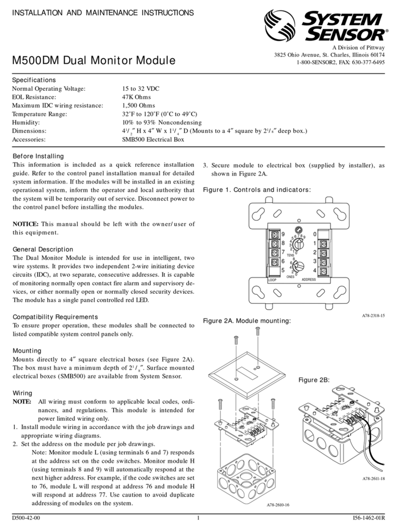
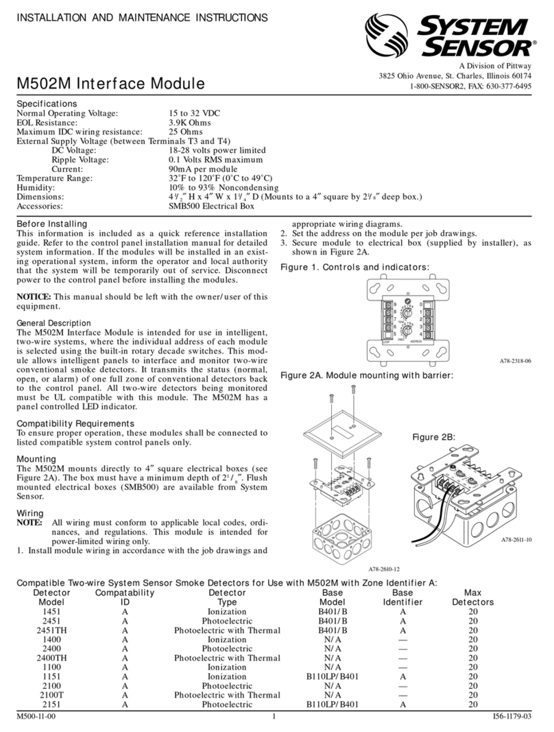
Figure 3. Typical 2-wire initiating circuit configuration, NFPA Style B:
Figure 4. Typical 4-wire fault tolerant initiating circuit configuration, NFPA Style D:
A78-2281-57
A78-2280-12
9
8
7
6
54
3
2
1
0
0
1
2
3
456789
TENS
ONES
ADDRESS
LOOP
0
1
2
3
456789
FROM PANEL OR
(+)
(–)
TO NEXT
(+)
(–)
DEVICE
(+)
(–)
MONITOR
CONNECT MODULES TO LISTED COMPATIBLE
32 VDC MAX.
SHIELDED-TWISTED PAIR
IS RECOMMENDED
CONTROL PANELS ONLY
PREVIOUS DEVICE
COMMUNICATION LINE
ALL WIRING SHOWN IS SUPERVISED AND POWER LIMITED
47 K EOL
RESISTOR
A2143-00
ANY NUMBER OF UL LISTED CONTACT CLOSURE
DEVICES MAY BE USED. DO NOT MIX FIRE
ALARM INITIATING, SUPERVISORY, OR
SECURITY DEVICES ON THE SAME MODULE.
IDC INSTALLATION WIRING SHALL NOT
EXCEED 40 OHMS OR 2500 FEET, 12 - 18 AWG.
INSTALL CONTACT CLOSURE DEVICES PER
MANUFACTURER'S INSTALLATION INSTRUCTIONS.
MODULE
9
8
7
6
54
3
2
1
0
0
1
2
3
456789
TENS
ONES
ADDRESS
LOOP
0
1
2
3
456789
MODULE
FROM PANEL OR
(+)
(-)
TO NEXT
(+)
(–)
DEVICE
(+)
(–)
MONITOR
CONNECT MODULES TO LISTED COMPATIBLE
CONTROL PANELS ONLY
PREVIOUS DEVICE
COMMUNICATION LINE
ALL WIRING SHOWN IS SUPERVISED AND POWER LIMITED
EOL RESISTOR
IS INTERNAL AT
TERMINALS 8 & 9.
ANY NUMBER OF UL LISTED CONTACT CLOSURE
DEVICES MAY BE USED. DO NOT MIX FIRE
ALARM INITIATING, SUPERVISORY, OR
SECURITY DEVICES ON THE SAME MODULE.
INSTALL CONTACT CLOSURE DEVICES PER
MANUFACTURER'S INSTALLATION INSTRUCTIONS.
32 VDC MAX
SHIELDED-TWISTED PAIR
IS RECOMMENDED
