manuals.online logo
Brands
  1. Home
  2. •
  3. Brands
  4. •
  5. Festo
  6. •
  7. Control Unit
  8. •
  9. Festo CPX-E- AO-U-I Series User manual

Festo CPX-E- AO-U-I Series User manual

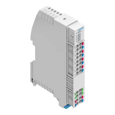
Analogue output modules
CPX-E-…AO-U-I
Festo AG & Co. KG
Ruiter Straße 82
73734 Esslingen
Germany
+49 711 347-0
www.festo.com
Instructions for use
Original instructions
8071083
2017-07
[8071085]
Analogue output modules CPX-E-…AO-U-I English..........................
Reproduction, distribution or sale of this document or communication of its con
tents to others without express authorization is prohibited. Offenders will be liable
for damages. All rights reserved in the event that a patent, utility model or design
patent is registered.
1 About this document
This document describes the use of the above-mentioned products. Certain
aspects of use are described in other documents and must be observed
è1.1 Further applicable documents.
1.1 Further applicable documents
Document Table of contents
Description of system CPX-E (CPX-E-SYS) Detailed description of system CPX-E
Instructions for using system CPX-E (CPX-E-SYS) Instructions and important notes on mounting,
electrical installation and maintenance tasks
for a system CPX-E
Description of analogue output modules
CPX-E-…AO-U-I (CPX-E-…AO-U-I)
Detailed description of product function and
parameterisation possibilities
Documentation for the components in a system
CPX-E and the connected peripherals
Information on using the components
Documentation for the higher-order controller
and the additional participants in the network
Information on commissioning and
parameterisation of the components
Fig. 1
For all available product documentation èwww.festo.com/pk
1.2 Product version
This document refers to the following product versions:
Product Version
CPX-E-4AO-U-I Analogue output module CPX-E-4AO as of Revision 1
Fig. 2
The product version can be identified from the product label or with the help of
appropriate software from Festo.
Suitable software for determining the product version is available on the
support portal of Festo èwww.festo.com/sp. Information on using the
software can be found in the integrated Help function.
There may be an updated version of this document for these or later
product versions.
 Check whether a corresponding version of this document is available on
the Festo Support Portal èwww.festo.com/sp.
1.3 Product labelling
The product label is located on the left-hand side of the module.
Scanning the printed Data Matrix Code with an appropriate device calls up the
Festo Support Portal, with information appropriate for the product. Alternatively,
the product key (11-digit alphanumeric code or product label) can be entered in
the search field of the Support Portal.
You can find detailed information on the product labelling in the descrip
tion of the module è1.1 Further applicable documents.
1.4 Specified standards
Version
EN 60529:2013-10 EN 61000-6-4:2007-01
EN 61000-6-2:2005-08 IEC 60204-1:2014-10
Fig. 3
2 Safety
2.1 General safety informations
 Take into consideration the legal regulations for the respective destination.
 Use the product only within the defined values è13 Technical data.
 Observe labelling on the product.
 Observe further applicable documents è1.1 Further applicable documents.
 Store the product in a cool, dry, UV-protected and corrosion-protected environ
ment. Ensure that storage times are kept to a minimum.
 Before working on the product: Switch off the power supply and secure it
against being switched on again.
 Comply with the handling specifications for electrostatically sensitive devices.
2.2 Intended use
The products described in this document are exclusively for use in systems CPX-E.
The products must be used only as follows:
– In an industrial environment only: Outside of industrial environments – in com
mercial and mixed-residential areas, for example – actions to suppress interfer
ence may have to be taken.
– Use only in combination with modules and components that are permissible for
the respective product variant èwww.festo.com/catalogue.
– Only use the product if it is in perfect technical condition.
– Only use the product in original status without unauthorised modifications. Only
the conversions or modifications described in this and the other applicable doc
uments are permitted.
2.3 Qualification of specialized personnel
Installation, commissioning, maintenance and disassembly should only be conduc
ted by qualified personnel.
The qualified personnel must be familiar with installation and operation of elec
trical control systems.
3 Further information
– Accessories èwww.festo.com/catalogue
– Spare parts èwww.festo.com/spareparts
4 Service
 Contact your regional Festo contact person if you have technical questions
èwww.festo.com.
5 Summary Product
5.1 Function
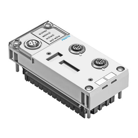
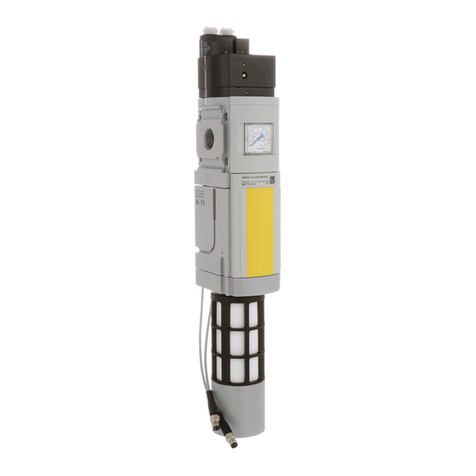
Analogue output modules CPX-E-…AO-U-I in a system CPX-E provide analogue
outputs for connecting actuators.
5.2 Product design
1LED indicators
2Terminal strips of outputs
[X0] … [X3]
3Terminal strip functional earth [X4]
4Terminal strip of load voltage
supply UOUT [XD]
5Terminal strip interlock
6Linking
2
3
45
6
1
Fig. 4
5.3 Display components
1Module error [P] (red)
2Channel error output 0 … 3 (red)
– Output 0 [X0]
– Output 1 [X1]
– Output 2 [X2]
– Output 3 [X3]
3Load voltage supply UOUT [PL]
(green)
1
2
3
Fig. 5
5.4 Connecting components
Port [X0], [X1], … Signal
0Output +
1+24 V DC output
2Output –
30 V DC output
Fig. 6
Port [X4]1) Signal
0Functional earth FE
1
2
3
1) The ports X4.0 … X4.3 are interconnected in the terminal strip.
Fig. 7
Port [XD]1) Signal
0+24 V DC load voltage supply UOUT
1
20 V DC load voltage supply UOUT
3
1) The connections XD.0 and XD.1 and also XD.2 and XD.3 are interconnected in the terminal strip.
Fig. 8
6 Conveying and storage
 Observe specifications for the environmental and storage conditions
è13 Technical data.
7 Connection
 Mount the module as outlined in the “Instructions for using system CPX-E”
è1.1 Further applicable documents.
8 Installation
Note
Malfunction due to electromagnetic interference.
 Only connect shields at the port for functional earth (FE) èFig. 4.
1. Make sure that the power supply is switched off.
2. Connect the lines to the terminal strips as outlined in the “Instructions for using
system CPX-E” è1.1 Further applicable documents.
9 Commissioning
You can find information on commissioning system CPX-E in the “Instruc
tions for using system CPX-E”. Information on the parameters can be found
in the “Description of system CPX-E” and the descriptions of the modules
being used è1.1 Further applicable documents.
Behaviour of the display components after error-free commissioning
[P] (red)1) [X0], [X1], … (red) [PL] (green)
Off Off Lights up
1) Flashes once briefly at the initialisation of the CPX-E system
Fig. 9
Information on troubleshooting in the event of incorrect behaviour can be
found in the “Description of system CPX-E” and the descriptions of the
modules being used è1.1 Further applicable documents.
10 Diagnostics and fault clearance
10.1 Diagnostics options
Various options are available for diagnosing errors:
– Internal system diagnostics
– LED indicators on the product
10.2 Internal system diagnosis
The internal system diagnostics process is described in the “Description of
system CPX-E” and the module descriptions
è1.1 Further applicable documents.
10.3 LED indicators
Module error [P]1)
LED (red) Significance Remedy
Lights up
Short circuit/overload on actuator
supply or module defective
1. Check the connected actuators,
eliminate short circuit/overload.
2. Switch the power supply UEL/SEN
off and on again.2)
Channel error. èFig. 11
Load voltage supply UOUT not present
or undervoltage 3)
 Check load voltage supply UOUT.
Off
normal operating status –
1) Flashes once briefly at the initialisation of the CPX-E system
2) The necessity of performing this step depends on the configuration of the parameter “Behaviour after
SCS” èDescription analogue output modules CPX-E-…AO-U-I.
3) If the “Load voltage supply undervoltage diagnostics” parameter is activated èDescription of ana
logue output modules CPX-E-…AO-U-I.
Fig. 10
Channel error [X0], [X1], …
LED (red) Significance Remedy
Lights up
Wire break/idling current output1)  Check lines and actuators and
replace where required.
Value exceeding nominal range/value
falling below nominal range
 Check analogue input.
 Check the parameterised limit
values.
 If necessary, deactivate monitoring.
Parameterisation errors  Check parameterisation and adjust.
Short circuit/overload or
undervoltage actuator supply
èFig. 10
Off
No channel error –
1) If output value ,2 mA:
– Error definitely incoming if RLš5 Ω
– Error definitely outgoing if RL›10 Ω
Fig. 11
Load voltage supply UOUT [PL]
LED (green) Significance Remedy
Lights up
Load voltage supply UOUT present –
Off
Load voltage supply UOUT not present
or undervoltage
 Check load voltage supply UOUT.
Fig. 12
11 Service
Note
Accumulation of heat due to reduced air supply to electronics.
 Keep the ventilation slots free and regularly remove contamination.
12 Disposal
 Dispose of the packaging and the product at the end of its useful life through
environmentally friendly recycling in accordance with applicable specifications.
13 Technical data
General remarks
Key feature Specification/value
General technical data, system CPX-E Description of system CPX-E
è1.1 Further applicable documents
Dimensions (length x width x height) [mm] 124.3 x 18.9 x 76.6
Product weight1) [g] 96
Mounting position Vertical/horizontal
Ambient temperature [°C] –5 … +60 (–5 … +50)2)
Storage temperature [°C] –20 … +70
Air humidity (non-condensing) [%] 0 … 95
Assigned address space (inputs/outputs) [Bit] –/64
Module code/submodule code (CPX-E-specific) 142/2
Module identification E-4AO
Degree of protection in accordance with EN60529 IP20
Protection against electric shock (protection
against direct and indirect contact in accordance
with IEC 60204-1)
Through the use of PELV circuits
(Protected Extra-Low Voltage)
Electromagnetic compatibility To EN 61000-6-2/-4
1) Including linking
2) With horizontal mounting position
Fig. 13
Power supply
Key feature Specification/value
Operating voltage supply UEL/SEN [V DC] 24 ± 25 %
Intrinsic current consumption at nominal
operating voltage 24 V from UEL/SEN
[mA] 65
Load voltage supply UOUT [V DC] 24 ± 25 %
Intrinsic current consumption at nominal
operating voltage 24 V from UOUT
[mA] 15
Capacitive load at load voltage supply UOUT [AF] 400
Fig. 14
Analogue outputs
Key feature Specification/value
Number of outputs 4
Max. cable length (shielded) [m] 30
Resolution (D-A converter, internal) [Bit] 15 + prefix
Digital value generation
Principle Successive approximation
Conversion time module [ms] š2
Settling time1)
Resistive load (voltage output) [ms] š0.9 (min. 1 kΩ)
Resistive load (current output) [ms] š0.1 (max. 500 Ω)
Capacitive load (voltage output) [ms] š1.8 (max. 1 μF)
Inductive load (current output) [ms] š0.07 (max. 1 mH)
Interference suppression
Crosstalk between outputs [dB] –40
Approved potential differences
Between 0 V UOUT and functional earth [V DC] –30 … +30
Between outputs and functional earth [V DC] –30 … +30
Electrical isolation
Between the channels No
Between the channels and UEL/SEN [V] Yes, DC 75/AC 60
Between UEL/SEN and UOUT [V]
Fault limits2)
Operating error limit (Tmin … Tmax) [%] ±0.3
Basic fault limit (at 25°C) [%] ±0.1
Temperature fault [%/K] ±0.01
Linearity error (at 25°C) [%] ±0.025
Repetition accuracy (at 25°C) [%] ±0.05
Data for encoder selection (voltage output)
Resistor [kΩ] ›1
Approved output voltage [V] –30 … +30
Short circuit protection Provided
Short circuit current [mA] 15
Data for encoder selection (current output)
Resistor [Ω] š500
Open circuit voltage [V] š19
Actuator supply
Actuator supply voltage [V DC] 24 ± 25 %
Max. sum continuous current per module [A] 2
Short circuit protection Electronic
Trigger level [A] ,2.7
Characteristic Slow-blowing
Behaviour after end of overload Parameterisable
Reverse polarity protection 24 V UOUT
against 0 V UOUT
Provided
Protection against reverse voltage [V DC] Max. UOUT
1) Until the stationary end value is reached with an accuracy of 1 % relative to FS (Full scale) (without
consideration of overshooting).
2) Relative to FS (Full scale)
Fig. 15

This manual suits for next models

1

Other Festo Control Unit manuals

Festo VZWP-L-M22C Series User manual

Festo

Festo VZWP-L-M22C Series User manual

Festo CDVI5.0 User manual

Festo

Festo CDVI5.0 User manual

Festo CPX-E-PB User manual

Festo

Festo CPX-E-PB User manual

Festo CMGA-E1-PB User manual

Festo

Festo CMGA-E1-PB User manual

Festo VPPL User manual

Festo

Festo VPPL User manual

Festo HMP-x-B Series User manual

Festo

Festo HMP-x-B Series User manual

Festo CPX-FVDA-P2 User manual

Festo

Festo CPX-FVDA-P2 User manual

Festo MH1 Series Parts list manual

Festo

Festo MH1 Series Parts list manual

Festo MSE6-E2M User manual

Festo

Festo MSE6-E2M User manual

Festo VUVG 1T1L Series User manual

Festo

Festo VUVG 1T1L Series User manual

Festo MSE6-C2M Parts list manual

Festo

Festo MSE6-C2M Parts list manual

Festo VAPB Series User manual

Festo

Festo VAPB Series User manual

Festo CPA VI Series User manual

Festo

Festo CPA VI Series User manual

Festo EHMD-40-RE Series User manual

Festo

Festo EHMD-40-RE Series User manual

Festo VIFB-21 Series User manual

Festo

Festo VIFB-21 Series User manual

Festo Compact Performance CP-FB6-E User manual

Festo

Festo Compact Performance CP-FB6-E User manual

Festo VZWE-Series User manual

Festo

Festo VZWE-Series User manual

Festo CPA-SC Series User manual

Festo

Festo CPA-SC Series User manual

Festo CP Factory User manual

Festo

Festo CP Factory User manual

Festo CPX-E Series Operating and installation instructions

Festo

Festo CPX-E Series Operating and installation instructions

Festo DW Series User manual

Festo

Festo DW Series User manual

Festo CAMC-G-S1 User manual

Festo

Festo CAMC-G-S1 User manual

Festo CPV..-DI01 series User manual

Festo

Festo CPV..-DI01 series User manual

Festo CPX-FB32 User manual

Festo

Festo CPX-FB32 User manual

Popular Control Unit manuals by other brands

Spirax Sarco SV615 Installation and maintenance instructions

Spirax Sarco

Spirax Sarco SV615 Installation and maintenance instructions

SYR STS 5 user manual

SYR

SYR STS 5 user manual

Elatec TWN4 MULTITECH LEGIC M user manual

Elatec

Elatec TWN4 MULTITECH LEGIC M user manual

Viessmann Vitotrol 350-C operating instructions

Viessmann

Viessmann Vitotrol 350-C operating instructions

eta G10.21A Technical Communication

eta

eta G10.21A Technical Communication

Graco CSP Series instructions

Graco

Graco CSP Series instructions

AWID SENTINEL-SENSE MPR-1510 Installation & operation manual

AWID

AWID SENTINEL-SENSE MPR-1510 Installation & operation manual

Waeco Switch200VTO Installation and operating manual

Waeco

Waeco Switch200VTO Installation and operating manual

Nortel 1100 Series user guide

Nortel

Nortel 1100 Series user guide

CLA-VAL CRL-60 Installation operation & maintenance

CLA-VAL

CLA-VAL CRL-60 Installation operation & maintenance

LOVATO ELECTRIC EXP10 02 instruction manual

LOVATO ELECTRIC

LOVATO ELECTRIC EXP10 02 instruction manual

Pilz PIT es Set10u-5ns (AIDA) basic operating manual

Pilz

Pilz PIT es Set10u-5ns (AIDA) basic operating manual

Vega VEGAKON 61 operating instructions

Vega

Vega VEGAKON 61 operating instructions

Cino FuzzyScan COMBO RM3230 user guide

Cino

Cino FuzzyScan COMBO RM3230 user guide

Moog D661K Series operating instructions

Moog

Moog D661K Series operating instructions

Leuze electronic AC-CPB quick start guide

Leuze electronic

Leuze electronic AC-CPB quick start guide

EHUOYAN YHY521X user manual

EHUOYAN

EHUOYAN YHY521X user manual

Lenovo ThinkServer TS430 user guide

Lenovo

Lenovo ThinkServer TS430 user guide

manuals.online logo
manuals.online logoBrands
  • About & Mission
  • Contact us
  • Privacy Policy
  • Terms and Conditions

Copyright 2025 Manuals.Online. All Rights Reserved.