Pittway NOTIFIER FCM Series User manual

DN-6724 — Page 1 of 4
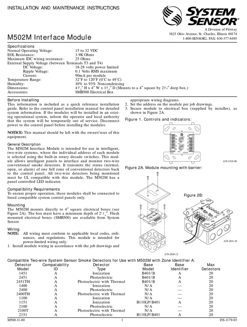
FCM-1 Module
(See wiring diagram Fig. 5 for FRM-1)
GENERAL
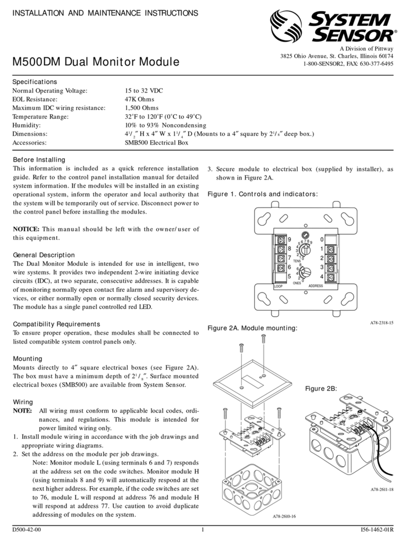
FCM-1 Control Module — The FCM-1 Addressable
Control Module provides the NOTIFIER AFC-600 control
panel for a circuit of Notification Appliances (horns, strobes,
speakers, etc.) or to monitor a telephone circuit.
Addressability allows the FCM to be activated, either manu-
ally or through panel programming, on a select (zone or
area of coverage) basis.
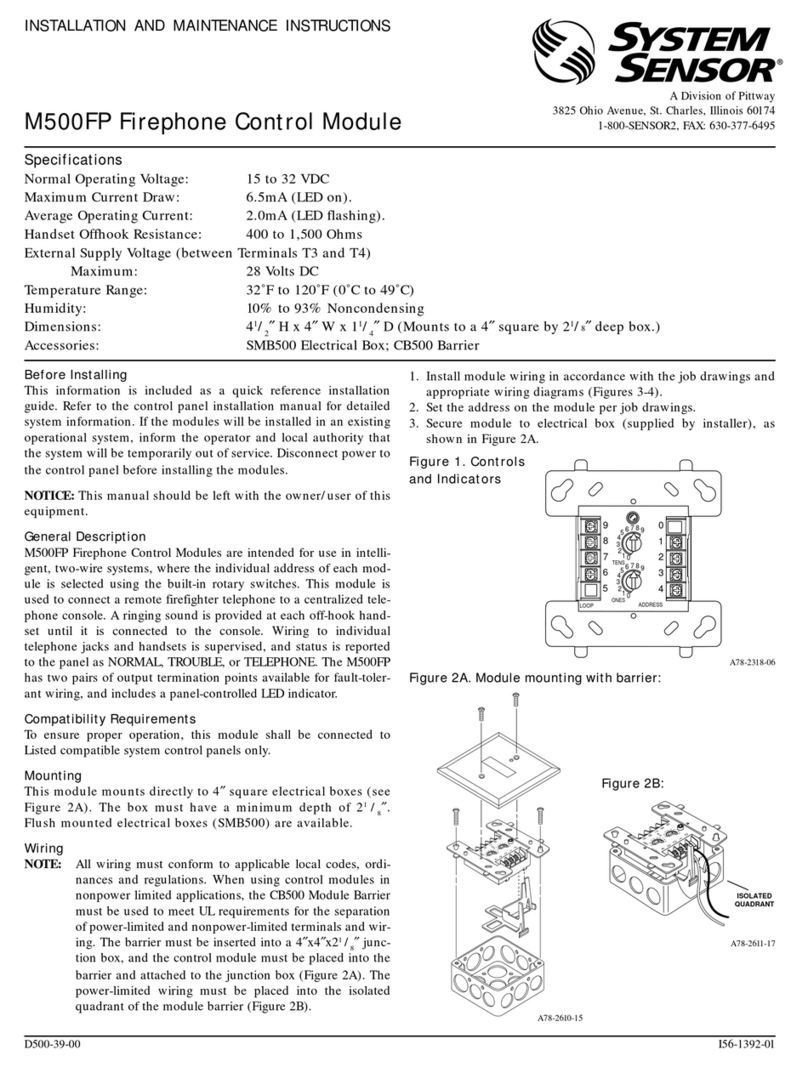
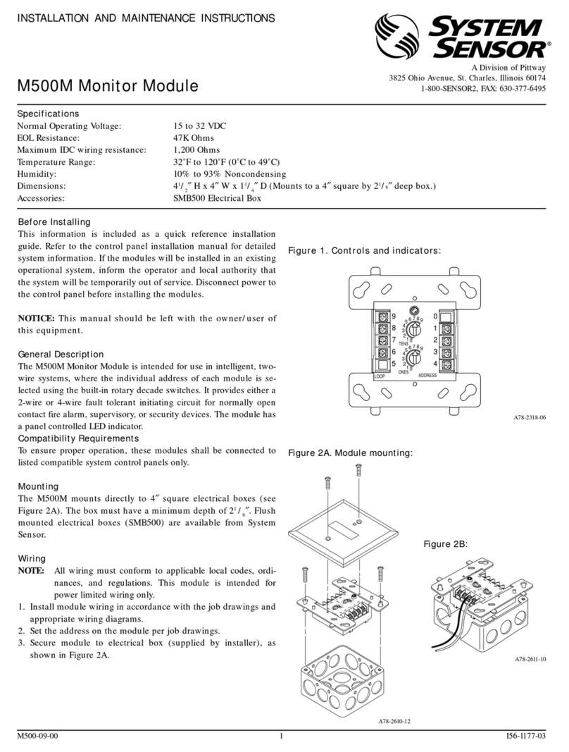
FRM-1 Relay Module — The FRM-1 Addressable Re-
lay Module provides the AFC-600 with a dry-contact output
for activating a variety of auxiliary devices, such as fans,
dampers, control equipment, etc. Addressability allows the
drycontacttobeactivated,eithermanuallyorthroughpanel
programming, on a select basis.
FlashScan (patent pending) is a new communication
protocol developed by NOTIFIER Engineering that greatly
enhances the speed of communication between analog in-
telligent devices. Intelligent devices communicate in a
grouped fashion. If one of the devices within the group
has new information, the panel CPU stops the group poll
and concentrates on single points. The net effect is re-
sponse speed
greater than five times
that of other de-
signs.
FEATURES
• Built-in type identification automatically identifies these
devices to the control panel.
• Internal circuitry and relay powered directly by two-wire
SLC loop. The FCM module requires power (for horns,
strobes, etc.), audio (for speakers), or a telephone riser
(for handsets).
• Built-in PS monitor replaces end-of-line relay (FCM only).
• Integral LED “blinks” green each time a communication
is received from the control panel and turns on in steady
red when activated.
• LEDblinkmaybedeselectedglobally(affects all devices).
• High noise immunity (EMF/RFI).
• TheFCMmaybeusedtoswitch 24-volt NAC power,audio
(up to 70.7 VRMS) or telephone.
• Wide viewing angle of LED.
• SEMS screws with clamping plates for wiring ease.
• Direct-dial entry of address (01-159).
• Speaker, audible/visual, and telephone applications may
be wired for Class B or A (Style Y or Z).
ISO-9001
Engineering and Manufacturing
Quality System Certified to
International Standard ISO-9001 Made in the U.S.A.
This document is not intended to be used for installation purposes. We try to keep our
product information up-to-date and accurate. We cannot cover all specific applications or
anticipate all requirements. All specifications are subject to change without notice. For
more information, contact NOTIFIER. Phone: (203) 484-7161 FAX: (203) 484-7118
One Fire-Lite Place, Northford, Connecticut 06472
FCM and FRM Series
Control and Relay Modules
with FlashScan
June 18, 1999 H-230
Section: Intelligent/Addressable Devices
PRELIMINARY
FlashScan™ is a trademark of NOTIFIER.
Noryl® is a registered trademark of GE Plastics, a subsidiary of
General Electric Company.
6724mod2.tif
APPLICATIONS
The FCM is used to switch 24 VDC audible/visual power,
high-level audio (speakers), or control telephone devices.
The FRM may be programmed to operate dry contacts for
door holders, Air Handling Unit shutdown, etc., and to re-
set four-wire smoke detector power.
CONSTRUCTION
• The face plate is made of off-white Noryl®.
• Controls include two rotary switches for direct-dial entry
of address (01-159).
• The FCM is configured for a single Class B (Style Y) or
Class A (Style Z) Notification Appliance Circuit.
• The FRM provides two Form-C dry contacts that switch
together.
OPERATION
Each FCM or FRM uses one of 159 possible module ad-
dresses on a SLC loop. It responds to regular polls from
the control panel and reports its type and status, including
the open/normal/short status of its Notification Appliance
S3705
Page 2 of 4 — DN-6724
RELAY CONTACT RATINGS
for both FCM and FRM models
PRODUCT LINE INFORMATION
FCM-1 Intelligent Addressable Control Module.
FRM-1 Intelligent Addressable Relay Module.
A2143-20 Capacitor, required for Class A (Style Z) op-
eration of speakers.
SMB500 Optional Surface-Mount Backbox.
CB500 Control Module Barrier — required by UL for
separating power-limited and non-power lim-
ited wiring in the same junction box as FCM-1.
noitpircseDdaoLnoitacilppA
mumixaM
egatloV
tnerruC
gnitaR
evitsiseRdedoC-noNCDV03A0.3
evitsiseRdedoCCDV03A0.2
evitsiseRdedoC-noNCDV011A9.0
evitsiseRdedoC-noNCAV521A9.0
)sm5=R/L(evitcudnIdedoCCDV03A5.0
)sm2=R/L(evitcudnIdedoCCDV03A0.1
)53.0=FP(evitcudnIdedoC-noNCAV521A5.0
Circuit (NAC). The LED blinks with each poll received. On
command, it activates its internal relay. The FCM super-
vises Class B (Style Y) or Class A (Style Z) notification or
control circuits.
Upon code command from the panel, the FCM will discon-
nect the supervision and connect the external power sup-
ply in the proper polarity across the load device. The dis-
connection of the supervision provides a positive indica-
tion to the panel that the control relay actually turned ON.
The external power supply is always relay isolated from
the communication loop so that a trouble condition on the
external power supply will never interfere with the rest of
the system.
Rotary switches set a unique address for each module.
The address may be set before or after mounting. The
built-in TYPE CODE (not settable) will identify the module
to the control panel, so as to differentiate between a mod-
ule and a sensor address.
A built-in magnetic test switch is provided to simulate a
short circuit on the NAC to test the FCM-1.
SPECIFICATIONS for FCM
Normal operating voltage: 15 to 32 VDC.
Maximum current draw: 5.1 mA (LED on).
Average operating current: 390 µA (LED flashing).
External supply voltage
(between Terminals T3 and T4):
maximum 80 volts (RMS or DC).
Drain on external supply: 2 mA maximum (using internal
EOL relay).
EOL resistance: 47K ohms.
Temperature range: 32°F to 120°F (0°C to 49°C).
Humidity range: 10% to 93% non-condensing.
Dimensions: 4.5" (114.3 mm) high x 4" (101.6 mm) wide
x1.25" (31.75 mm) deep. Mounts to a 4" (101.6 mm)square
x 2.125" (53.975 mm) deep box.
SPECIFICATIONS for FRM
Normal operating voltage: 15 to 32 VDC.
Maximum current draw: 5.1 mA (LED on).
Average operating current: 270 µA (LED flashing).
EOL resistance: not used.
Temperature range: 32°F to 120°F (0°C to 49°C).
Humidity range: 10% to 93% non-condensing.
Dimensions: 4.5" (114.3 mm) high x 4" (101.6 mm) wide
x1.25" (31.75 mm) deep. Mounts to a 4" (101.6 mm)square
x 2.125" (53.975 mm) deep box.
6724mt1.wmf
6724mt2.wmf
MOUNTING
DIAGRAMS
Note CB500 Module Barrier,
which creates isolated quadrant.
6724rate.tbl

DN-6724 — Page 3 of 4
The Face Plate
6724face.wmf
WIRING DIAGRAMS
The following wiring diagrams are provided:
1) FCM-1: Typical notification appliance circuit configuration,
NFPA Style Y.
2) FCM-1: Typical fault-tolerant notification appliance circuit
configuration, NFPA Style Z.
3) FCM-1: Typical wiring for speaker supervision and switch-
ing, NFPA Style Y.
4) FCM-1: Typical fault-tolerant wiring for speaker supervision
and switching, NFPA Style Z.
5) FRM-1: Relay module wiring diagram.
Fig. 1
FCM-1: Typical notification appliance circuit configuration, NFPA Style Y.
Fig. 2
FCM-1: Typical fault-tolerant notification appliance circuit configuration, NFPA Style Z.
• Connect modules to listed compatible NOTIFIER control panels only.
• All wiring shown is supervised and power limited.
• Module polarities are shown in alarm.
• Connect modules to listed compatible NOTIFIER control panels only.
• All wiring shown is supervised and power limited.
• Module polarities are shown in alarm.
6724wir1.wmf
6724wir2.wmf

Page 4 of 4 — DN-6724
Fig. 3
FCM-1: Typical wiring for speaker supervision and switching, NFPA Style Y.
• Connect modules to listed compatible
NOTIFIER control panels only.
• All wiring shown is supervised.
• Wires must be supervised per NFPA.
• Module polarities are shown in alarm.
Fig. 4
FCM-1: Typical fault-tolerant wiring for speaker supervision and switching, NFPA Style Z.
• Connect modules to listed compatible NOTIFIER control panels only.
• All wiring shown is supervised.
• Wires must be supervised per NFPA.
• Module polarities are shown in alarm.
6724wir3.wmf
6724wir4.wmf
6724wir5.wmf
Fig. 5
FRM-1: Relay module
wiring diagram.
• Connect modules to listed
compatible control panels only.
• Module does
NOT
supervise
controlled circuits.
NOTES regarding AUDIO AMPLIFIER in Figures 3 & 4 above.
1) Audio circuit wiring must be twisted-pair as a minimum. See NOTIFIER installation manual for detailed information.
2) When a 70.7 V audio amplifier is used, terminals 1 and 2 are power limited, while terminals 3 through 9 are non-power limited. In
this case, the CB500 barrier is required. Otherwise, all terminal wiring is power limited. The CB500 includes a label indicating which
terminals are non-power limited. This label MUST BE PLACED adjacent to the nameplate label, which is on the module housing.
This manual suits for next models
3
Other Pittway Control Unit manuals

Pittway
Pittway System Sensor MOD400R User manual

Pittway
Pittway NOTIFIER LDM Series User manual

Pittway
Pittway SYSTEM SENSOR M500FP User manual

Pittway
Pittway NOTIFIER UZC-256 Installation manual

Pittway
Pittway SYSTEM SENSOR M502M User manual

Pittway
Pittway SYSTEM SENSOR M500M User manual

Pittway
Pittway Fire-Lite Alarms MMF-300 User manual

Pittway
Pittway SYSTEM SENSOR M500DM User manual

Pittway
Pittway System Sensor M500DR User manual

Pittway
Pittway System Sensor MB500 User manual