D300-03-10 I56-1720-011Pittway Tecnologica S.r.l. Via Caboto 19/3, 34147 TRIESTE, Italy
Avvia OK
INCREMENTALE
Modal Ind.
OK
Esc Esc
OK
OK Fail
Success
Connessione
in Corso
...>Fine
Inizia
Transm. Nuove
Impostazione
OK
Connessione
fallita
* iprovare?*R
Continua
Se la manutenzione ha dato esito
soddisfacente, questa funzione scriverà
la data corrente nella memoria del
rivelatore quale ultima manutenzione, in
caso contrario l’S300PTU visualizzerà un
messaggio di avvertimento Contaminato/
Non Valido. Se la data di manutenzione
è stata programmata correttamente,
essa verrà visualizzata sul display
dell’S300PTU.
Nota: La pressione del tasto Esc in caso
di Connessione Fallita può provocare
la memorizzazione di una data errata.
Tuttavia, ciò non pregiudica il corretto
funzionamento del rivelatore.
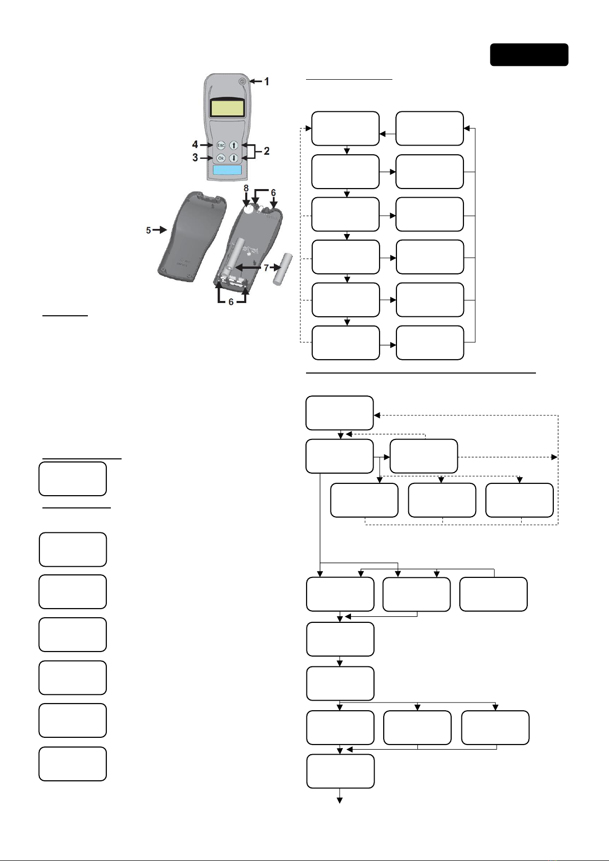
4 SCRITTURA DELLA DATA DI MANUTENZIONE
3 SCRITTURA IMPOSTAZIONI RIVELATORE
Seleziona e scrive nuove impostazioni al rivelatore.
Livello
Sensibilita
-----------
Ultima
Manutenzione
DD MMM YYYY
Impost.
LED Disp.:
------------
Data
Fabbricaz.
MMM AAA
Metodo
Allarme
------------
Visualizzerà Livello Sensibilità
per rivelatori Ottici e Ottico-Termici
oppure Metodo Allarme per il
rivelatore Termico
Il livello sarà Basso, Medio o Alto
Il Metodo sarà a Temp. fissa o
Derivativo
Visualizza l’ultima data di manutenzione
Visualizza il modo operativo del LED verde,
Lampeggiante o Spento in condizioni normali
Visualizza la data di fabbricazione
Utilizzare i tasti su/giù per selezionare
l’indirizzo desiderato (01 to 99)
epremere OK per confermare
Nota: Solo gli indirizzi da 1 a 32 sono
validi sull’S300ZDU
Utilizzare i tasti su/giù per selezionare
il livello di sensibilità (Basso/Medio/
Alto) e premere OK per confermare
Nota: I rivelatori sono forniti con
sensibilità impostata al livello Medio
Utilizzare i tasti su/giù per selezionare
Spento - LED spento in condizioni
normali
Lampegg. - Lampeggio verde del
LED in condizioni normali
La schermata Dati Dispositivo Incompleti indica che il rivelatore che si è tentato di acquisire
è di tipo incompatibile, ad esempio appartenente alla serie ECO1000. Premere Esc per
ritornare alla Inizia Trasm. Nuove Impostazioni.
Il messaggio Dati Rivelatore Corrotti segnala che il rivelatore non funziona correttamente a
causa di una scrittura incompleta delle impostazioni effettuata precedentemente. Premere
Esc per ritornare alla Inizia Trasm. Nuove Impostazioni.
Dopo aver completato la procedura di scrittura delle impostazioni, è buona norma verificarle
utilizzando la Acquisizione Impostazioni Rivelatore (vedere sezione 2).
La modalità di indirizzamento incrementale programma sensori con
indirizzi sequenziali. Usare i tasti su/giù per selezionare l’indirizzo
di partenza e premere OK per programmare il primo rivelatore.
L’indirizzo successivo viene selezionato automaticamente, premere
OK per programmare il prossimo rivelatore.
Importante: vedere la nota sopra relativa all’uso del tasto Esc
in caso di Connessione Fallita.
Indir. 3.1
Dispositivo
Sel d r. In i .
e imipr OK
01
Livello 3.2
Sensibilita
LED 3.3
Dispositivo
Selez.
Impost. LED
-------- OK
Imposta 3.4
Sirena
Cambia Suono
Sirena:
X OK
Inizia OK
Transm. Nuove
Impostazione
Scritt. 3
Impostazioni
Rivelatore
OK
OK
OK
OK
OK
Nuovo Liv.
Sensibilita
-------- OK
OK
OK
OK
OK
OK Connessione
in rsCo o
...>Fine
OK
Esc
Fail
Success
Esc No
Esc
Continua
Imposta
NON UTILIZZATO
Dati Rivelatore
Corrotti
Dati
Dispositivo
Incompleti
Connessione
fallita
* iprovare?*R
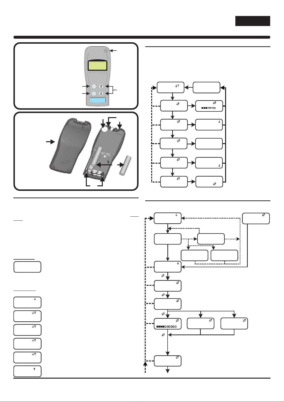
La trasmissione al rivelatore delle nuove impostazioni viene iniziata
confermando con OK il messaggio Inizia Trasm. Nuove Impostazioni. La
schermata Connessione in Corso viene visualizzata per alcuni secondi,
l’indicatore a barra esprime l’avanzamento dell’operazione. Al termine
della programmazione, l’S300PTU ritorna schermata Inizia Trasm. Nuove
Impostazioni.
La schermata Connessione Fallita compare in caso di mancata connessione
o di comunicazione interrotta. In tal caso, la connessione viene ritentata
premendo OK.
Nota: Dalla schermata Connessione Fallita è possibile ritornare alla
Inizia Trasm. Nuove Impostazioni premendo due volte Esc se l’indicatore
a barra era visualizzato prima dell’interruzione della comunicazione e le
nuove impostazioni del rivelatore comprendevano la modifica del livello di
sensibilità ottica. In tutti gli altri casi è sufficiente una sola pressione del
tasto Esc. Si raccomanda di operare con estrema cautela.
AVVERTENZA
Una comunicazione incompleta delle nuove impostazioni del rivelatore
e la seguente pressione del tasto Esc causano la perdita dei dati
rivelatore nell’S300PTU e possono compromettere il funzionamento
del rivelatore. In tal caso, il rivelatore deve essere ritornato al fornitore
per la riprogrammazione.
!
Connessione
in Corso
...>Fine
Contaminato
Non ovalid
OK
OK
Esc
Fail
Scrit. 4
NUOVO DATA
Manutenzione
Connessione
fallita
* iprovare?*R
Ultima
Manutenzione
DD MMM YYYY
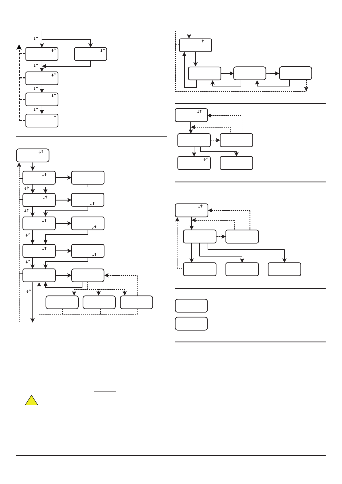
5 TEST ALLARME
Questa opzione fa eseguire un test di camera ottica al rivelatore che, in caso superi la
verifica, viene posto in condizione di allarme. In caso la camera ottica sia guasta o necessita
di pulizia, il relativo messaggio verrà visualizzato sul display dell’S300PTU.
A larmle
5
Test
Pre OK xmi 2
Contaminato
No V on alid
Dispositivo
in l eA larm
Camera
DIFETTOSA
Rimpiazzare
OK
OK OK
Esc
Fail
OK
Connessione
in Corso
...> Fine
Connessione
fallita
* iprovare?*R
Impostato
Nota: Prima di effettuare questa
procedura, notificare a chi di
competenza che il rivelatore viene
sottoposto a verifica.
Quando il rivelatore è in condizione
di allarme, la comunicazione con
l’S300PTU non è possibile ed il
rivelatore deve essere re-inizializzato
dalla centrale di controllo.
6 ALTRE SCHERMATE
Alcune schermate possono apparire in qualunque momento, queste sono:
Batterie
PTU
Scariche
PTU
Guasto!
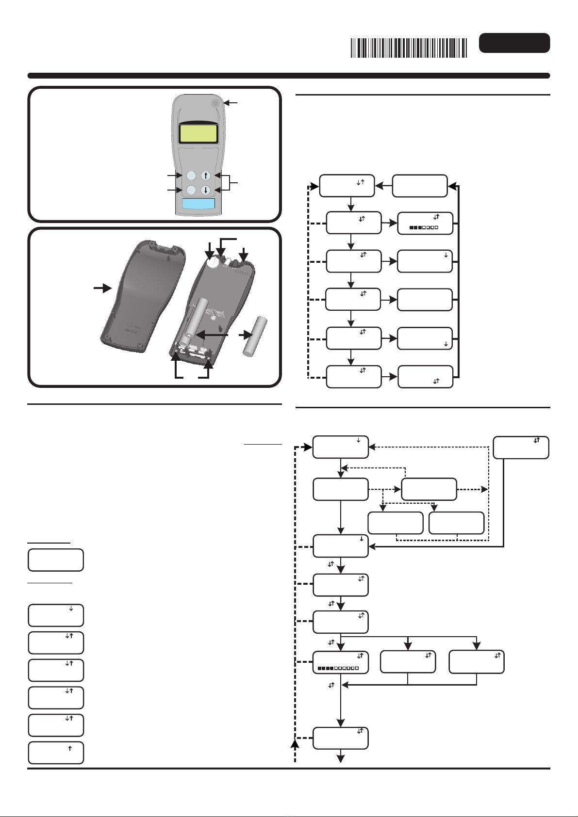
Sostituire le batterie dell’S300PTU. Con riferimento ai Figura 2
riportati sul fronte della pagina e la Sezione 7 di seguito
Perdita di informazioni data/ora. La sua batteria è scaduto. L’unità
non può essere riparato e deve essere sostituito
7 SOSTITUZIONE DELLA BATTERIA
Nota: Vedere la Figura 2 in prima pagina.
Alle batterie si accede svitando le quattro viti (8) e rimuovendo il coperchio posteriore
(5).
Le batterie (7) sono 3 x LR03.AAA 1.5V. Assicurarsi di rispettare le polarità corrette.
ATTENZIONE: Non rimuovere la batteria tampone (6) si perderebbero le
informazioni di data/ora ed il funzionamento dell’S300PTU stesso. Non
manomettere nessuna parte del circuito, si potrebbero causare danni
permanenti, l’unica operazione ammessa è la sostituzione delle batterie.