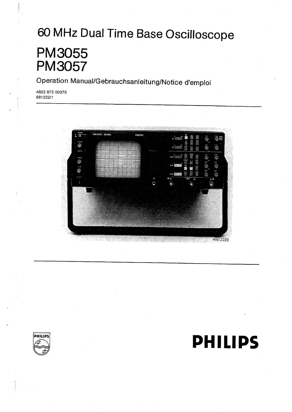
Philips PM3055 User manual
Other Philips Test Equipment manuals

Philips
Philips PM 3206 User manual

Philips
Philips PM 6302 User manual

Philips
Philips PM3055 User manual

Philips
Philips GM 5605 User manual

Philips
Philips PM 3214 User manual

Philips
Philips MPX2 User manual

Philips
Philips PM 3210 User manual

Philips
Philips PM 3218 User manual

Philips
Philips PM 3256U User manual

Philips
Philips Optimus User manual