AFL FOCIS Duel User manual

FOCIS Duel
Fiber Optic Connector Inspection System
User Guide
www.AFLglobal.com or (800) 321-5298, (603) 528-7780
Test & Inspection

2
Safety Information..........................................4
General Information ........................................5
FOCIS Duel | aeRos®Solution Overview..............................5
FOCIS Duel Fiber Optic Connector Inspection System..................5
aeRos .....................................................5
FOCIS App .................................................5
Made for iPad - Legal Notice ....................................5
How to View Device Information Menu ..............................6
Warranty Terms and Conditions....................................6
Repair Services ................................................6
Standards Compliance Information .................................6
FOCIS Duel Overview ........................................7
Controls, Display, Interfaces ......................................7
Battery Charging and Operation ...................................7
FOCIS Duel Optical Inspection Ports ................................8
Getting Started ............................................9
Powering Up/Down .............................................9
Enabling Optical Inspection Ports ..................................9
Properly Installing and Removing Adapter Tips ........................10
Port 2 Functionality .........................................11
Inspection Live Image Mode ......................................11
Port 1 Functionality .........................................12
Live Image Mode Features........................................12
Capture Key Operation ..........................................12
Captured Image Mode Features....................................13
Pass/Fail Results Table.........................................14
Image Information Screen ......................................15
Port 1: Main Menu and Settings ...............................16
Main Menu Overview ...........................................16
Settings Menu Overview . . . . . . . . . . . . . . . . . . . . . . . . . . . . . . . . . . . . . . . . . 16
IEC Pass/Fail Analysis ...........................................17
Example IEC Rule ............................................17
Setting Pass/Fail Criteria .......................................18
Configuring Auto-Save and Auto-Send ..............................20
Configuring Bluetooth ...........................................21
Power Save Setting . . . . . . . . . . . . . . . . . . . . . . . . . . . . . . . . . . . . . . . . . . . . . 21
Set Time and Date ..............................................21
Port 1: Saving Captured Images ...............................22
Saving to the Current Folder ......................................22
Saving to a Newly Created Folder ..................................22
©2018 AFL , all rights reserved. FOCIS-DUEL-1000 Revision AA, 2018-04-25
Table of Contents

3
Saving to an Existing Folder.......................................22
Configuring Image Pairing........................................23
Port 1: Viewing Saved Results (Results Manager) .................24
Opening Image Files - Reviewing Saved Results........................24
Creating New Jobs/Cables/Files....................................24
Deleting Jobs/Cables/Files ........................................24
Port 1: Using FOCIS Duel with FOCIS App ........................25
Port 1: Sharing Captured Test Results...........................26
Sending Captured Results to FlexTester/FlexScan ......................26
Configuring Bluetooth.........................................26
Manually Send Results to FlexTester/FlexScan .........................26
Uploading Inspection Results to a PC ...............................27
Inspection Reporting using TRM®2.0 ...............................27
Table of Contents

4
Safety Information
IMPORTANT! Proper care in handling should be taken when using any precision optical test
equipment. Scratched or contaminated optical connectors can impact the performance of the instrument.
NOTE! FOCIS Duel contains no user serviceable parts. This instrument must be returned to AFL or
authorized agents for repair.
IMPORTANT! It is important to keep connector end-faces on the launch and receive cables and those
on the Fiber Under Test (FUT) clean, to ensure accurate measurements and operation.
CAUTION! Never view a live ber. Never look directly into the optical outputs of ber optic network
equipment, test equipment, patch cords and jumpers. Laser radiation is harmful to eyes.
WARNING! Use only the specied AC adapter. Use of another type of AC adapter can damage the
instrument and create the danger of re and electrical shock.
WARNING! To avoid the danger of re and electrical shock:
• Never use a voltage that is different from that for which the AC adapter is rated.
• Do not plug the unit into a power outlet that is shared by other devices.
• Never modify the power cord or excessively bend, twist, or pull it.
• Do not allow the power cord to become damaged. Do not place heavy objects on the power cord or
expose it to heat.
• Never touch the AC adapter while your hands are wet.
• Should the power cord become seriously damaged (internal wiring exposed or shorted), contact the
manufacturer to request servicing.
NOTE! Refer to your company’s safety procedures when working with optical systems.
NOTE! Follow your company’s approved cleaning procedures.

5
“Made for iPad” means that an electronic accessory has been designed to connect specically to iPod,
iPhone, or iPad, respectively, and has been certied by the developer to meet Apple performance standards.
Apple is not responsible for the operation of this device or its compliance with safety and regulatory
standards. Please note that the use of this accessory with iPod, iPhone, or iPad may affect wireless performance.
–iPad, and Retina are trademarks of Apple Inc., registered in the U.S. and other countries.
–iPad mini is a trademark of Apple Inc., registered in the U.S. and other countries.
–Android is a trademark of Google Inc.
Made for iPad - Legal Notice
FOCIS Duel | aeRos®Solution Overview
AFL's FOCIS Duel Fiber Optic Connector Inspection System paired with aeRos cloud with FOCIS App
features a complete ber optic connector inspection and workow and data management solution.
FOCIS Duel Fiber Optic Connector Inspection System
FOCIS Duel is a self-contained twin-ported Bluetooth connected ber optic connector inspection probe
with integrated screen. The rst port (right hand side Port 1) is fully featured, identical to AFL’s FOCIS
Flex. The second port (left hand side Port 2) has fast and convenient female LC “click-in” adapters, auto-
focus and 2X zoom capabilities. The FOCIS Duel can perform IEC, IPC, AT&T and user-dened end-face
cleanliness analysis and store Port 1 images and reports locally. The AFL FOCIS App (iOS and Android)
provides a comprehensive and user-friendly feature set as well as connectivity with AFL’s cloud-based
aeRos®workow automation platform.
aeRos
aeRos is an open, cloud-based, workow management platform that facilitates two-way communication
and data exchange from engineering to project management to your technician in the eld. Now
everyone has access to test results and can address challenges in real-time. aeRos allows project
managers to send jobs directly to technicians, dening tests and congurations as needed. Throughout
the job, managers can monitor technicians' progress and help to solve problems as they arise.
aeRos solution is available in two options: aeRos BASIC and aeRos PRO:
aeRos®BASIC account — Data Management solution that allows users to save their test data in the
aeRos Cloud and then retrieve it from anywhere at any time with a standard Internet browser. aeRos
BASIC is free to all owners of AFL’s aeRos enable test equipment.
aeRos®PRO account — Workow Management solution that allows users to manage their entire
testing workow and enables seamless and efcient communications and data management. aeRos
PRO is available in annual and lifetime License congurations.
FOCIS App
By pairing the FOCIS Duel inspection probe with the FOCIS App and aeRos PRO, users are enabled to
control their test hardware directly from their Android or iOS smart devices. With aeRos PRO account,
test projects and setups can be created and predened in aeRos cloud, and then pushed to the smart
device app to simplify the test process for technicians. Technicians receive a notication on their
smart device and can work on scheduled projects. As the project is completed, inspection results are
automatically synchronized with the cloud for instant access, analysis, and reporting.
FOCIS App is available via Google play store or App Store.
General Information

6
Standards Compliance Information
FOCIS Duel has been designed and tested to comply with the relevant sections of any applicable
specications including full compliance with all essential requirements of the applicable EU Directives.
USA Repair and Calibration services
AFL Test & Inspection Division
16 Eastgate Park Road
Belmont, NH 03220
603-528-7780
800-321-5298
Warranty Terms and Conditions
AFL Test & Inspection products are warranted against defective material and workmanship for a period
of (1) one year from the date of delivery to the end user. Optional Extended Warranty starts at the end
of the standard (1) one year warranty period. Any product that is found defective within the warranty
period, will (at the discretion of AFL) be repaired or replaced. Warranty will be voided if the product has
been repaired or altered by other than an authorized AFL repair facility or when it has been subjected to
misuse, negligence, or accident.
In no case shall AFL liabilities exceed the original purchase price.
Repair Services
Please contact customer service for a return authorization number prior to sending your AFL test
equipment in for repair or calibration.
General Information
How to View Device Information Menu
• From the Live Image mode, press the Main Menu Akey to
access the Main Menu screen.
• Press Up/Down arrow keys to navigate and highlight the
Device Info menu B.
• Press Select Cor Right arrow key to display a sub-screen
of the Device Info menu, which will display the following Info:
–Device name
–Serial number
–Controller version number
–User Interface version Number
• Press Back Dsoft key to return to Live Image mode.
Note: It is helpful to have your FOCIS Duel Device Information
available if you need to contact AFL Test & Inspection Customer
Service or Technical Support.
A
F
L
T
e
s
t
&
I
n
s
p
e
c
t
i
o
n
Contains Bluetooth Transceiver Module
FCC ID: X3ZBTMOD8
IC ID: 8828A-MOD8
A
C
B
D

7
Controls, Display, Interfaces
FOCIS Duel Overview
1. Power key -
2. Image Capture key -
3. F1 soft key (typically Back function)
4. F2 soft key (typically Select function)
5. Navigation and Edit functional keys
6. Display (2-inch Color LCD [320 x 240])
7. Micro-USB port
8. 5 VDC input jack
9. Charging indicator
1
2
3
4
5
6
7
8
9
Battery Charging and Operation
• Plug the included AC Charger into AC outlet.
• Connect charger plug into 5 VDC jack 8.
• LED 9indicates charging status as follows:
–OFF - AC not connected
–RED - Charging battery
–GREEN - Fully charged
–RED/GREEN ashing - Charging error. Verify
correct 5VDC 2A charger is used. Allow to
cool before charging.
• FOCIS Duel charges while operating.
• Battery icon Aon FOCIS Duel screen indicates
battery state as follows:
- AC connected; charging, not fully charged
- AC connected; charging, fully charged
- Battery operation, fully charged
- Battery operation, partially charged
- <15 min Battery operating time remaining
6
7
9
2
43
1
8
5
A
8
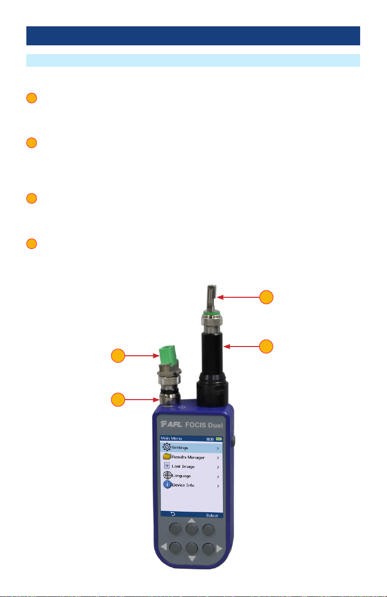
FOCIS Duel Optical Inspection Ports
FOCIS Duel Overview
FOCIS Duel is a self-contained twin-ported Bluetooth connected ber optic connector inspection probe.
1. Port 1 – This is fully featured optical inspection port.With the press of a single button, Port 1 auto-
focuses, captures, centers and analyzes the end-face image to industry standard IEC 61300-3-35
(2015), IPC, AT&T and user-dened criteria. Port 1 is compatible and interworks over Bluetooth with
the FOCIS App (on iOS and Android smart devices).
2. Port 1 adapter tip – Interchangeable adapter tips support single and multi-ber connector
inspection for a wide range of patch cords and bulkhead-mounted connectors having either PC/
UPC or APC polished end-faces. A key on the probe snout combined with a slot on the adapter
tips assures that adapter tips never loosen during use, under any circumstances. Quad-slotted APC
adapter tips ensure the screen is visible in any use case.
3. Port 2 - The functionality of Port 2 is limited. Port 2 features fast and convenient female click-in
adapters, auto-focus and 2X zoom capabilities. Port 2 is intended for subjective inspection only.
There is no image capture or end-face automatic pass/fail analysis on Port 2. No FOCIS App support
or aeRos cloud support for Port 2.
4. Port 2 adapter tip– A slot on the adapter tips combined with a keyed snout eliminates loosening
during normal use. Port 2 adapter tips are available for all common connector types – Universal
1.25 mm and 2.5 mm, SC and LC in both UPC and APC polish types.
1
2
3
4
1
3
4
2

9
Getting Started
FOCIS Duel powers up in the initial Live Image Mode screen F.
While in the Live Image screen, use the left arrow key Gto select between the two inspection ports.
The selected port is identied by its label H, either “1” or “2”, which is displayed in the top left of the
Live Image screen to indicate the user’s selection.
G
H
F
D
C
B
E
Powering Up/Down
Enabling Optical Inspection Ports
Power-Up
• Press and release the Power key A.
Power-Down
• Press and hold the Power key Auntil display turns off.
Congure FOCIS Duel to Auto-Off
• From the Main Menu select Settings B, press Select
• Select Display & Power Save C.
• Select Auto Off D.
• Select the desired power save option E:
2 min, 5 min, 10 min, Never.
A
10
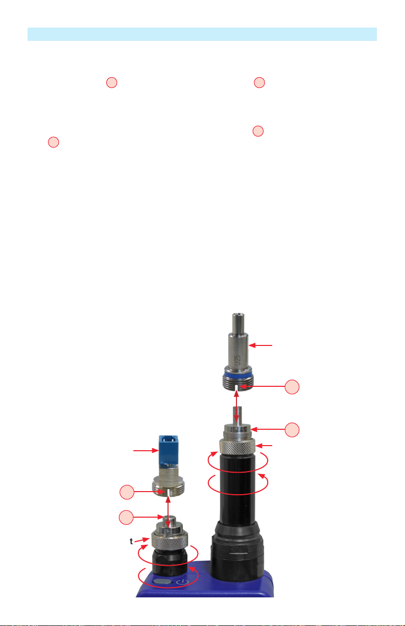
Port 2 Adapter Tip
Properly Installing and Removing Adapter Tips
Port 1 interchangeable adapter tips support single and multi-ber connector inspection for a wide range
of patch cords and bulkhead-mounted connectors having either PC/UPC or APC polished end-faces. A
key on the probe snout Acombined with a slot on the adapter tip Bassures that adapter tips never
loosen during use, under any circumstances. Quad-slotted APC adapter tips ensure the screen is visible in
any use case.
Port 2 adapter tips are available for all common connector types – Universal 1.25 mm and 2.5 mm, SC
and LC in both UPC and APC polish types. A slot on the adapter tip Dcombined with a key on a probe
snout Celiminates loosening during normal use.
Installing Adapter Tips
• Align a slot on the adapter tip with a key on the probe snout.
• While holding adapter tip in place, raise captive nut until it engages with adapter tip threads.
• Turn captive nut counter-clockwise (viewed from front/top).
• Hand-tighten (do not over-tighten).
Removing Adapter Tips
Probe tips are held in place with a captive nut.
• Turn captive nut clockwise (viewed from front/top).
• Continue until captive nut is free of adapter tip.
• Remove adapter tip by pulling it gently straight off the probe base.
A
C
Captive nut
Port 1 Adapter Tip
Captive nut
B
D
Tighten
Loosen
Tighten
Loosen

11
Inspection Live Image Mode
Port 2 Functionality
Port 2 is intended for subjective inspection only.
Functional Keys
1. Zoom/Help key (2x/?) has two functions:
–Long press initiates Help function and displays the on-screen Help menu.
–Short press toggles 1X/2X zoom for the selected Port 2.
–The label shown over the functional key Awill be displayed as follows:
2X/?, if 1X zoom enabled
1X/?, if 2X zoom enabled
2. Menu key: Press to display the Main menu.
3. Up/Down arrow keys: Used for manual focus.Vertical slider Bon the FOCIS Duel display
indicates the current focus level relative to focus range.
4. Left arrow key: In Live Image node, toggles between Port 1 and Port 2 images.
5. Right arrow key: Press to autofocus. When using the LC female style “click-in” adapter, once
the rst LC (UPC or PC) end-face has been auto-focused, subsequent LC connectors of the same
polish type (APC or UPC) will each be in focus without further user action, enabling rapid subjective
connector end-face cleanliness and surface condition assessments. However, additional auto-focus
of manual focus may be needed, if connectors are with different polish angles.
6. Capture button is disabled for Port 2!
1
2
3
4
5
6
3
2
Port 2 6
1
B
54
A
12
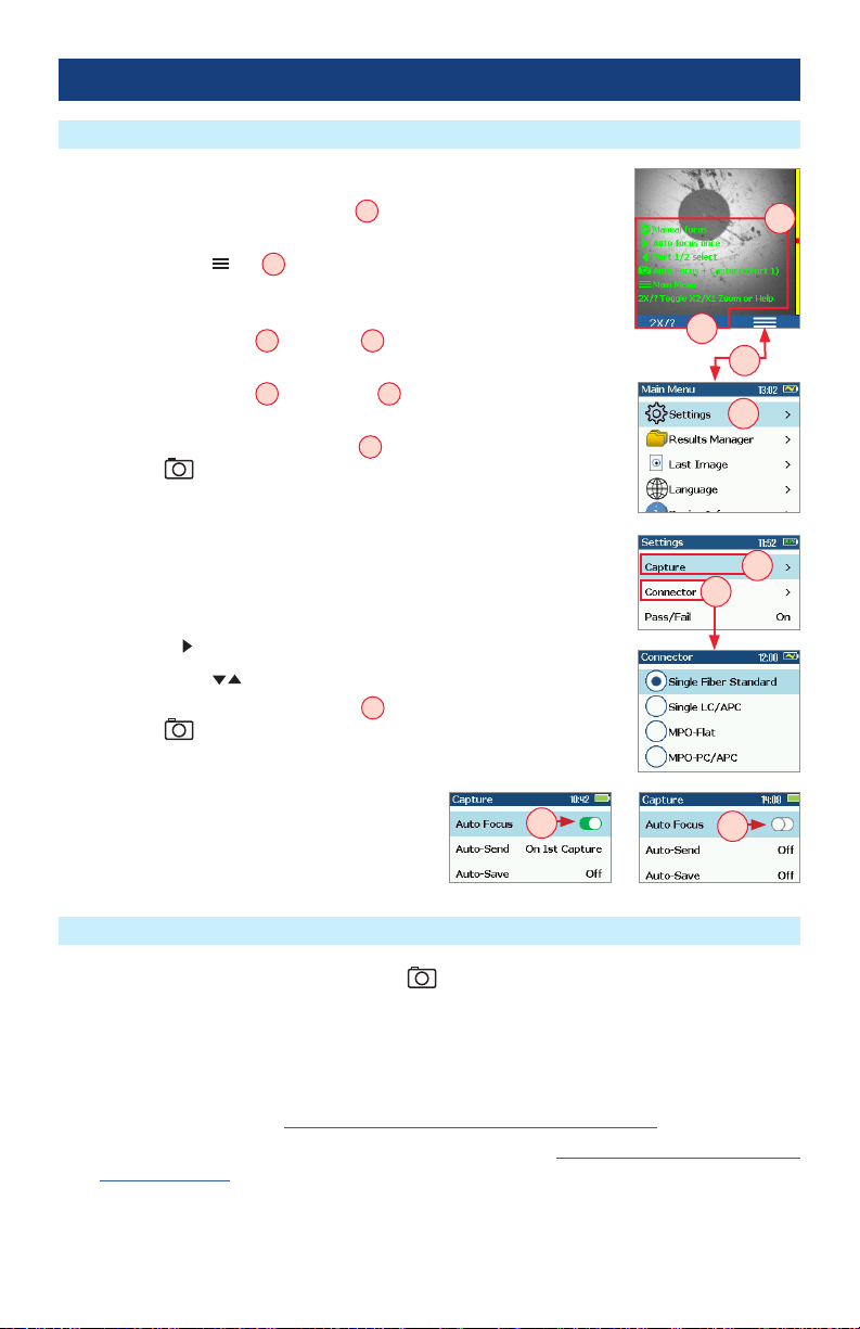
Live Image Mode Features
Capture Key Operation
FOCIS Duel powers-up in the Live Image mode.
• Pressing and holding Zoom/Help key Adisplays help tips about
FOCIS Duel keys usage.
• Pressing the Menu key Bdisplays the Main Menu that allows the
user to set preferences, perform general settings, manage saved test
results and perform other non-test functions.
• Pressing Menu > Setting C> Capture Ddisplays the Capture
settings menu.
• Pressing Menu > Setting C> Connector Eallows the user to select
connector type.
• When the Auto Focus option is enabled Fin the Capture screen and
Capture key is pressed:
–Auto focus is initiated
–Image is captured when auto focus completes
–Image is analyzed if Pass/Fail set to On
–FOCIS Duel transitions to Captured Image mode
• When Auto Focus is enabled or disabled:
–Press Right arrow key to auto focus once
–Press Up/Down arrow keys to manually adjust focus
• When the Auto Focus option is disabled Gin the Setting screen and
Capture key is pressed:
–Image is captured (without adjusting focus)
–Image is analyzed if Pass/Fail set to On
–FOCIS Duel transitions to Captured
Image mode
• In the Live Image mode, press the Capture key to perform the following:
–Auto Focus image (if the Auto Focus option is enabled)
–Capture the displayed image and enter the Captured Image mode
–Analyze image (if the Pass/Fail option is enabled)
–Save results and send image to Bluetooth-paired device (if auto-save and auto-send enabled on
“1st Capture Key”, see “Conguring Auto-Save and Auto-Send” on page 20 for details)
–If auto-save or auto-send enabled on “2nd Capture Key” (see “Conguring Auto-Save and Auto-
Send” on page 20), press the Capture key again to save and/or send
• In Captured Image mode, press the Capture key to return to Live Image mode.
• In the Main Menu or Settings modes, press the Capture key to return to the most recent Live or
Captured Image mode.
A
A
B
C
E
D
G
F
Port 1 Functionality

13
Captured Image Mode Features
Port 1 Functionality
Once an end-face image has been captured and analyzed, a zoomed-out view of the end-face and
results is displayed.
# Description
1. Screen Title: displays File Name (e.g. COO1-003) if saved image is shown
or Captured @ hh:mm:ss if unsaved image is shown.
2. Pass/Fail Indication: shown only if Pass/Fail option is enabled in Settings.
3. Display Tabs: select the desired view using the Left/Right ◄arrow keys.
4. End-face Image: displays end-face image with Pass/Fail overlay (if enabled).
5. Back soft key: press to return to previous screen.
6. Image Layers soft key: use Up/Down keys to view image layers as follows,
• End-face image with overlay layer shown (default view)
• End-face image only
• Overlay only
7. Menu soft key: press to display the Save/Send Menu.
1
2
3
4
5
6
7
Zoomed in end-face image with Overlay
1
2
5
4
3
7
Failing scratches/defects
highlighted in RED
Passing scratches/defects
highlighted in GREEN
6
- Zoomed Out Image
- Partially Zoomed In
Image
- Fully Zoomed In Image
- Pass/Fail Results Table
- Image Information
14
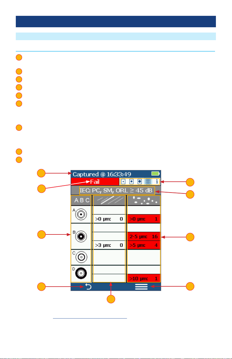
Pass/Fail Results Table
Port 1 Functionality
Note: See section “Setting Pass/Fail Criteria” on page 18 for details on how to select and/or edit
pass/fail analysis rules.
# Description
1. Screen Title: displays File Name (e.g. COO1-003) if saved image is shown or Captured @ hh:mm:ss
if unsaved image is shown.
2. Pass/Fail Indication: shown only if Pass/Fail option is enabled in Settings.
3. Display Tabs with the Pass/Fail display tab selected.
4. Analysis Rule applied to determine Pass/Fail.
5. Analysis Zones: A - core, B - cladding, C - adhesive, D - contact area.
6. Scratch analysis results for each zone:
• Reports the number of detected scratches exceeding limit for each region
• Highlights failed rules in RED
7. Defect analysis results for each zone:
• Reports the number of detected defects exceeding limit for each region
• Highlights failed rules in RED
8. Back soft key: press to return to previous screen.
9. Menu soft key: press to display the Save/Send Menu.
1
2
3
4
5
6
7
8
9
2
1
5
89
3
4
7
6

15
Image Information Screen
# Description
1. Screen Title: displays File Name as follws:
• <Cable>-<Fiber> (e.g. COO1-003) if saved image is shown
• ‘Captured @ hh:mm:ss’ if unsaved image is shown
2. Pass/Fail Indication: shown only if Pass/Fail option is enabled in Settings.
3. Display Tabs with the Image Information display tab selected.
4. Results ID eld: indicates default folder/le names.
• Blue highlighted indicates that results are not saved.
5. Time & Date eld: indicates Time & Date of the displayed captured image.
6. Rule eld: indicates pass/fail analysis rule applied.
7. Back soft key: press to return to previous screen.
8. Menu soft key: press to display the Save/Send Menu.
1
3
4
5
6
7
8
87
Port 1 Functionality
Note: See section “Port 1: Saving Captured Images” on page 22 for details on how to name and
save results.
2
2
4
5
6
1
3

16
Main Menu Overview
Main Menu
The Main Menu is accessed from Live Image mode by pressing the Menu soft key. Main Menu is used
to select user preferences, perform general settings, manage saved test results, and perform other non-
test functions.
While in the Main Menu:
• Press Up/Down arrow keys to navigate and select (highlight)
one of the menu item as follows.
–Settings: Use to congure Auto Focus, Pass/Fail criteria,
Bluetooth, and general settings
–Results Manager: Use to navigate and review or send
saved test results
–Last Image: Use to recall most recently viewed image
–Language: Select the FOCIS Duel User Interface Language.
13 Language options to select from: English, Spanish,
French, Polish, German, Japanese, Italian, Turkish, Russian,
Finnish, Simplied Chinese, Traditional Chinese, Korean
–Device Info: Use to view serial number, software revision, etc
• Press Select Aor Right arrow key to display a sub-screen of the
selected menu item.
• While in a sub-screen, press Up/Down arrow keys to navigate and highlight the desired option.
–Press Select soft key or Right arrow key to edit highlighted parameter
–When selected parameter displays On/Off icon / , press Select to enable/disable
• Press Back Bsoft key to return to Live Image mode.
Port 1: Main Menu and Settings
Settings Menu Overview
While in the Settings Menu:
• Press Up/Down arrow keys to navigate and select (highlight) the
desired menu item.
• For Beeper settings:
–Pressing Select soft key toggles setting between enable/disable.
–Pressing Right arrow key enables setting.
–Pressing Left arrow key disables setting.
• For all other settings, press Select soft key or Right arrow key to
display a sub-menu and edit the selected parameter.
• Press Back soft key to return to the previous menu screen.
• Press Capture Key to return to live image mode.
A
B

17
IEC Pass/Fail Analysis
Port 1: Main Menu and Settings
IEC 61300-3-35 denes connector inspection pass/fail criteria.
Pass/Fail criteria depends on:
• Fiber type (SMF or MMF)
• Connector end face regions
–A region: Core
–B region: Cladding
–C region: Adhesive (between cladding
and ferrule)
–D region: Physical contact area
• Type of end face aw:
–Scratches
–Defects (contamination, particles, chips)
• Size of aw
Core
Failing
Defect
Passing
Defect
Contact
Adhesive
Cladding
Shown below is the display when the IEC rule for single-mode PC connector with return loss ≥ 45 dB is
selected. The table identies the number of scratches or defects of a certain size, which may be allowed
in each of the core, cladding, and contact regions.
Example IEC Rule
Region Scratch Defect
A: Core
>0 µm: 0
No scratches >0 µm
allowed
>0 µm: 0
No defects >0 µm
allowed
B: Cladding
>3 µm: 0
No scratches >3 µm
allowed
2-5 µm: 5
Up to 5 defects 2-5 µm
diameter allowed
>5 µm: 0
No defects >3 µm
allowed
C: Adhesive
Blank
(No limitations on
scratches)
Blank
(No limitations on
scratches)
D: Contact
Blank
No limitations on
scratches
0 ≥ 10 µm
No defects ≥ 10 µm
allowed

18
Setting Pass/Fail Criteria
Port 1: Main Menu and Settings
Pass/Fail menu is accessed from the Live Image mode > Main Menu > Settings.
Enable/disable Auto Analysis
• Highlight Auto Analysis A.
• Use Select key Bto enable/disable / Pass/Fail analysis.
Change Rule:
• Highlight Change Rule C.
• Press Select or Right arrow key to display a list of the available Rules D.
• Use Up/Down arrow keys to highlight the desired Rule group E.
• Press Select or Right arrow key to display a sub-list F.
• Use Up/Down arrow keys to highlight the desired rule.
• Press Use Gto apply the selected Rule in Pass/Fail analysis.
View Rule
• Highlight View Rule H.
• Press Select or Right arrow key to view details for the current rule.
• User Rules may be edited while viewing.
H
A
C
B
G
E
DF

19
Edit User Rule:
• Highlight the Change Rule option A.
• Press Select or Right arrow key to display a list of Rules sub-screen B.
• Highlight the User Rules group.
• Press Select to display a list of User Rules C.
• Use Up/Down arrow keys to highlight the desired rule to edit.
• Press the Right arrow key to view details screen for currently selected rule.
• While in the Rule details screen D, use arrow keys to highlight the desired Region and Scratches/
Defects parameter.
• Press Select to display the Limits Editor screen E.
• Use Left/Right arrow keys to select a digit.
• Use Up/Down arrow keys to change the value.
• Press Ok Fto conrm changes.
Setting Pass/Fail Criteria
Port 1: Main Menu and Settings
F
A
B C
D E

20
Conguring Auto-Save and Auto-Send
Port 1: Main Menu and Settings
1. From the Main Menu, select Settings > Capture > Auto Focus
• Use to enable or disable the auto-focus option / as needed.
1
2. Highlight and Select Auto-Send. Use to disable auto-send, enable on 1st Capture key, or enable
on 2nd Capture key.
3. Highlight and Select Auto-Save. Use to disable auto-send, enable on 1st Capture key, or enable
on 2nd Capture key.
4. Highlight and select Save to Folder/File. Use to select and edit the desired folder/le eld.
When Auto-Send/Save is enabled, press Capture from Live Image mode to auto-focus (if enabled),
capture image, analyze pass/fail (if enabled), then send image and pass/fail results to paired device and
save image and pass/fail results to congured Job/Cable folder.
Note: If Auto-Save or Auto-Send on 2nd Capture key is enabled, you will be prompted to press the
Capture key again to save or send. Press the Back key if you do not wish to save or send image.
2
3
4
1 1
2
4
3
Other manuals for FOCIS Duel
1
Table of contents
Other AFL Test Equipment manuals


AFL
AFL Noyes OPM4-4 User manual

AFL
AFL FOCIS Lightning 2 User manual

AFL
AFL FlexScan FS200 OTDR User manual

AFL
AFL M710 Series Installation instructions

AFL
AFL WDM900 User manual

AFL
AFL MLP4-2 User manual

AFL
AFL FLX380 User manual

AFL
AFL Noyes OPM4-3D User manual

AFL
AFL VFI 2 User manual

AFL
AFL Noyes OPM4 User manual


