9
Disassembly
1. Remove the screws (4 pcs) that secure the right-
hand side panel, and take off the panel.
2. Remove the screws that secure the control panel
(2a). Disconnect the cables from the block (2b)
between the oven chambers. Be sure to mark the
cables so they can be fitted back correctly. Discon-
nect the contact (2c) on the lower part of the control
panel.
Now, for each oven chamber (or deck), do the
following:
- Remove the thermostat’s sensor (2d), which is
located inside the oven chamber on the right.To do
this, bend out the fixing clips using a pair of pliers.
Remove the sensor through the hole at the upper-
right lamp socket.
- Remove the screw and then remove the thermal
overload sensor (2e).
- Disconnect the contact (2f) from the lower side
of the circuit board. (Remember, there is one such
contact for each oven chamber or deck.)
- Now take off the control panel.
3. Remove the screws (4 pcs) that secure the left side
panel, and remove the panel.
4. Remove all screws that secure the back panel, and
remove the panel.
5. Remove the screws (2 pcs) that secure the narrow,
front-right side-panel, and remove the panel.
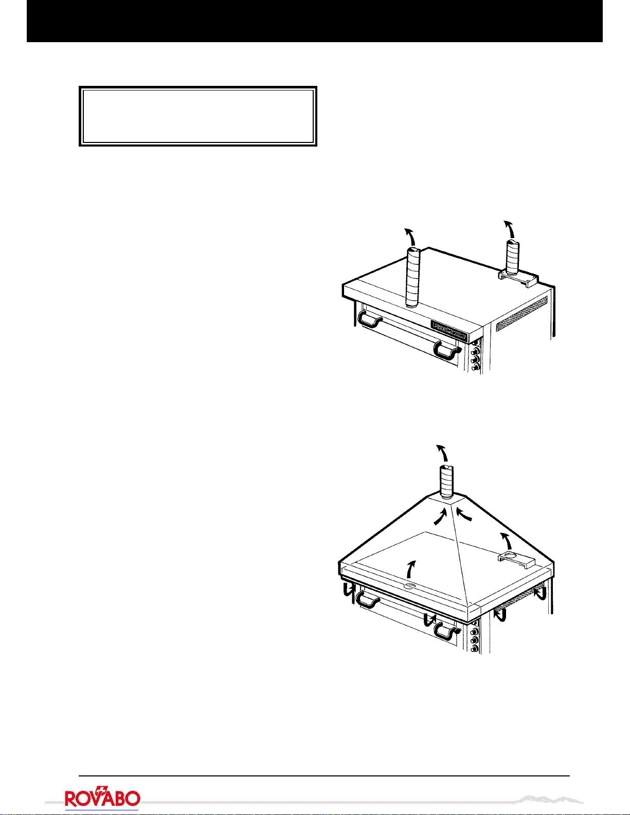
6. Unscrew and remove all the oven-vent knobs.Open
the oven door(s). Remove the screw (1 pc per deck)
that secures the left side of the pillar (6) to the
inside-right of the oven-door frame(s). Now remove
the pillar.
7. Remove the outside screws (2 pcs) that secure the
narrow, front-left side-panel (7).Then, with the oven
door(s) open, remove the screw (1 pc per deck) that
secures the right side of the panel to the inside-left
of the door frame(s).Now remove the panel.
8. Remove the screws from the middle cross-member
(8), and remove the member.
9. Remove the hearth strip (9).
10.Remove the self-tapping screws that fix the indi-
vidual oven decks to each other. Follow the order
described below. (Note that screw quantities are per
deck):
a. – the screws (3 pcs) that secure the front left corner
b. – the screw (1 pc) that secures the back left corner
c. – the screw (1 pc) that secures the back right corner
d. – the screws (6 pcs) that secure the front right
corner.
The decks can now be separated. Lift off each deck
by moving it first backward and then upward.The
oven is now completely disassembled.
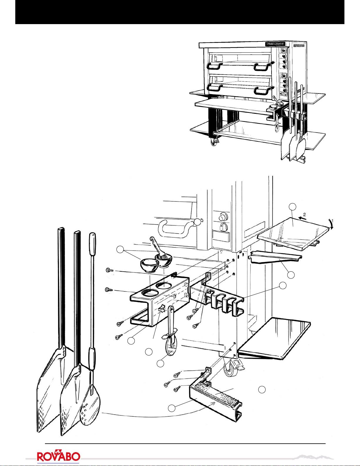
Assembly – Divisible oven
Assembly
Important! Be sure to fit the 2 legs with the lockable
wheels to the front of the oven and the 2 legs with non-
lockable wheels to the back.
11.Lift the lower oven-deck safely and fit the legs using
the M10x30 bolts (12 pcs) + 20x10.5 washers (12
pcs) provided.For each leg, first screw in (but do
not tighten) the internal bolt, i.e. the one that has to
be inserted through the top inside of the leg.Then
screw in the 2 external bolts, but do not tighten.
Finally, tighten the 3 bolts progressively and alter-
nately to fix the leg firmly to the oven.
12.Fit the slide rails (4 pcs) to the legs as shown in the
illustration, using the self-tapping screws provided
(16 pcs).
13.Insert the sliding shelf into either the upper or the
lower pair of rails, as required. (1 sliding shelf is
supplied as standard)
14.Mount the remaining oven decks and secure them in
place using the screws 10 a-d removed at point 10.
15.Fit parts 3-9 using the screws provided.
16.Now, for each oven chamber (or deck):
- Insert the thermostat’s sensor (2d) through the
hole in the upper-right lamp socket.Secure the
sensor in the three fixing clips on the right of the
oven chamber. Fix it into place by bending the fixing
clips using a pair of pliers.
- Fit the thermal overload sensor (2e) as shown in
the illustration, using the screw provided (1 pc).
- Fit the control panel (2a) and secure it in place with
the screws provided.
- Connect the contact (2c) in the lower part of the
control panel to the corresponding contact on the
oven.
- Connect the contact (2f) to the lower side of the
printed circuit board.
- Fit and secure the cables to block (2b).
17.Fit the steam duct, using the screws provided (4
pcs).
18.Fit the flue diverter, using the self-tapping screws
provided (4 pcs).
Important! Make sure the open long-side faces
forward.
19.Fit the exhaust outlets (2 pcs).
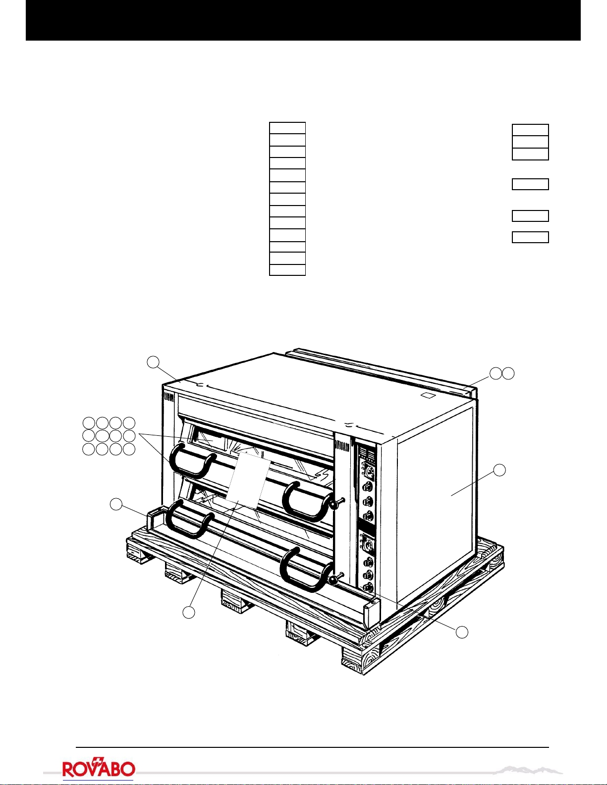
20.Remove the wooden supports that keep the hearth-
stones in place.
21.Remove all protective plastic film from the oven.
Info!
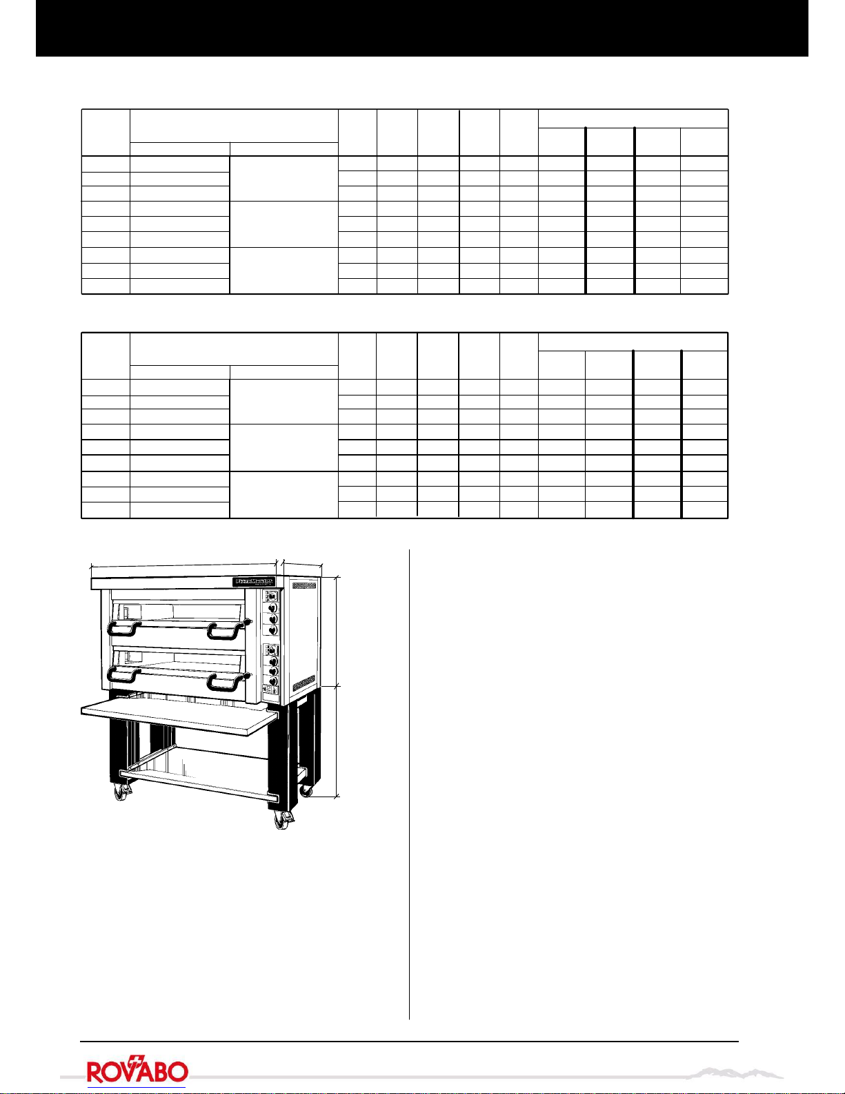
Weight per oven deck: approx. 150 kg
Important!
Do not remove the wooden supports for the hearth-
stones until you reach point 20 below.
Do not use the oven-door handles or oven-vent
knobs to lift the oven, for it can damage the oven.