Planer 370-M Series User manual

®
Series 370-M & 570-M
Instructions for use
© 2023 Planer Limited
Original instructions
MA201231-M-EN 1.0.1


3
Series 370-M & 570-M: Instructions for use MA201231-M-EN 1.0.1
Table of Contents
1. Introduction 5
1.1 Notices ............................................................................................................................ 6
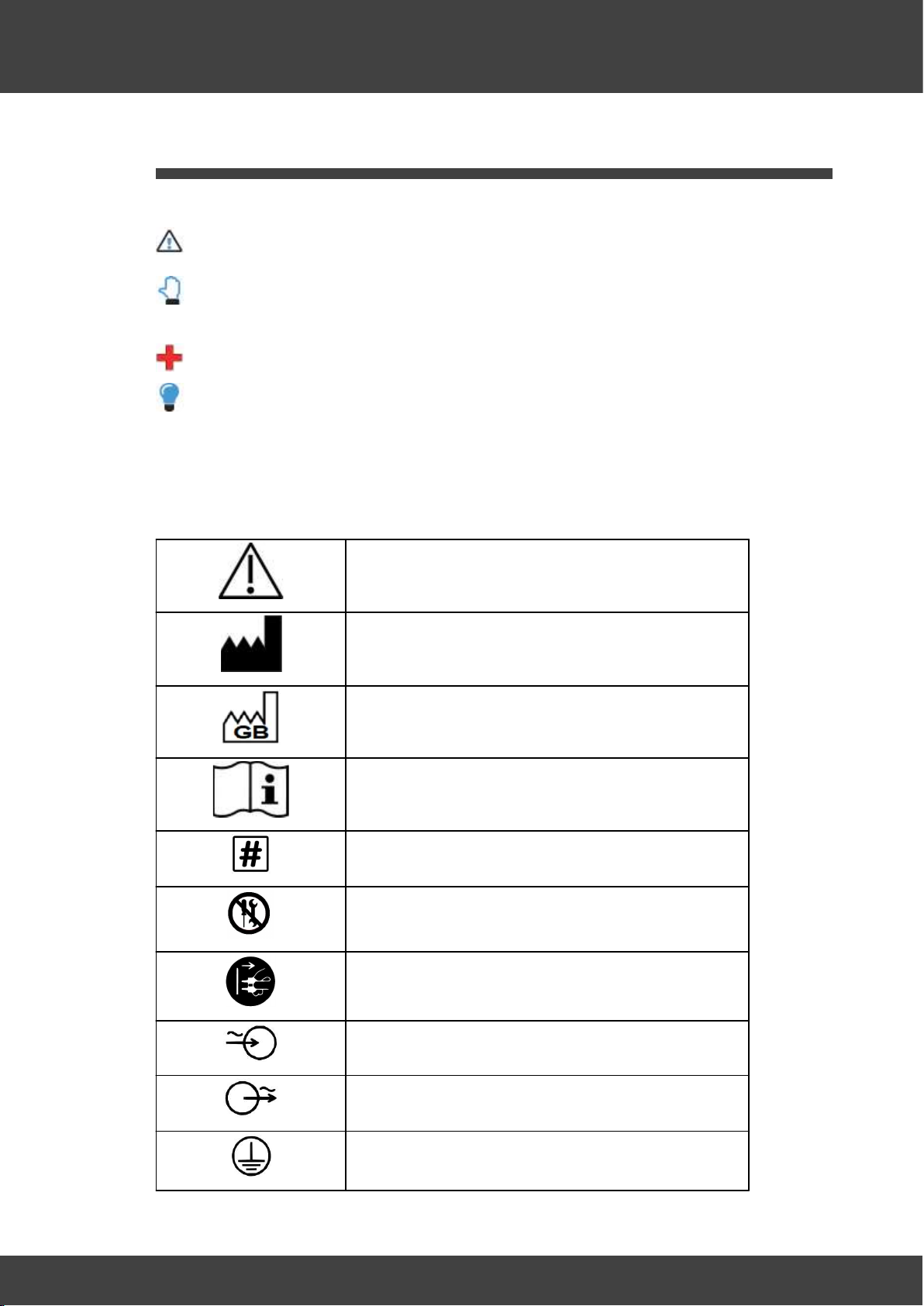
1.2 Symbols ........................................................................................................................... 7
1.2.1 Symbols used in this manual .................................................................................... 7
1.2.2 Symbols used on the equipment .............................................................................. 7
1.3 Safety precautions ......................................................................................................... 8
1.3.1 First aid ..................................................................................................................... 9
1.3.2 Safety ........................................................................................................................ 9
1.3.2.1 Equipment .................................................................................................................................................. 9
1.3.2.2 Liquid nitrogen and vessels ................................................................................................................. 10
1.3.3 EMC Precautions .................................................................................................... 11
1.4 Intended use statement .............................................................................................. 11
1.5 Theory of operation .................................................................................................... 11
1.6 Equipment overview ................................................................................................... 12
1.6.1 370 freezer ............................................................................................................. 12
1.6.2 570 freezer ............................................................................................................. 12
1.6.3 MR7 controller ........................................................................................................ 13
1.6.3.1 Guide to the MR7 controller ................................................................................................................. 13
1.6.4 Connection overview .............................................................................................. 14
1.6.4.1 Chamber ................................................................................................................................................... 14
1.6.4.2 MR7 controller ........................................................................................................................................ 16
2. Operating the equipment 19
2.1 Installation .................................................................................................................... 20
2.1.1 Installing the liquid nitrogen supply ...................................................................... 20
2.2 Using a Planer pump and dewar ................................................................................ 21
2.3 Configuring the controller .......................................................................................... 21
2.4 Freezing samples .......................................................................................................... 21
2.4.1 Loading the samples in the lid assembly ............................................................... 21
2.4.2 Preparing the nitrogen supply ................................................................................ 22
2.4.3 Starting the run ....................................................................................................... 22
2.4.4 Loading the samples using an MR7 ....................................................................... 23
2.4.5 Removing the samples ........................................................................................... 24
2.5 Reports .......................................................................................................................... 24
2.6 Switching off the system ............................................................................................. 25
3. Routine maintenance and troubleshooting 27
3.1 Routine maintenance .................................................................................................. 28
3.2 Calibrating the system ................................................................................................. 29
3.3 Troubleshooting ........................................................................................................... 29
3.3.1 Unexpected reset ................................................................................................... 29
3.3.2 The run has stopped prematurely .......................................................................... 29

4
Series 370-M & 570-M: Instructions for use MA201231-M-EN 1.0.1
Table of Contents
3.3.3 The chamber will not cool ...................................................................................... 30
3.3.4 The chamber will not heat ..................................................................................... 30
3.3.5 No response from the system ................................................................................ 31
3.3.6 Returning for service .............................................................................................. 31
3.4 Disposal ......................................................................................................................... 31
4. Additional information 33
4.1 Specifications ............................................................................................................... 34
4.1.1 System specifications ............................................................................................. 34
4.1.2 MR7 Controller specifications ................................................................................ 34
4.1.3 Chamber specifications .......................................................................................... 35
4.1.4 Fuses ...................................................................................................................... 36
4.2 External alarms ............................................................................................................. 36
37
INDEX

Introduction

6
Series 370-M & 570-M: Instructions for use MA201231-M-EN 1.0.1
Introduction
1 Introduction
This document contains important information concerning the safe use of the equipment.
Ensure that you have read and fully understand these instructions before attempting to
use this equipment.
1.1 Notices
Instructions for use: Series 370-M & 570-M
Issue: 1.0.1 2023-07-27
© 2023 Planer Limited
Original instructions
Planer Limited. 110 Windmill Rd., Sunbury-on-Thames, Middlesex,
TW16 7HD, UK. Tel: +44 (0)1932 755000; email: sales@planer.com
Serious incidents that occur with this device should be reported to Planer Ltd and the
competent authority of the Member State in which the user and/or patient is established.
This equipment contains batteries and other components that have a limited life. To
ensure the long life of the equipment and help ensure trouble-free operation, we
recommend that you join one of our Maintenance and Support Schemes. Please contact
your supplier for details.
Good practice demands that in critical applications, reliance should not be placed on a
single source of data. Hard copies and backup copies should be routinely kept.
All equipment supplied by Planer Limited is subject to a Warranty Agreement and
Limited Liability. In addition, software products are not sold but are licensed for use and
are subject to a Licence Agreement.
You may freely copy and distribute this document for personal use in any form provided
that the document is reproduced in full and includes these notices. Individual pages and
forms may be freely copied for the purposes of implementing any instructions within the
documentation. You may not make modifications or create derivative works. Any
modification to these conditions requires the written permission of Planer Limited.
Product names and designations that are referred to in this document may be
trademarks or registered trademarks or both and are recognised as the property of their
respective owners.
This information is provided without warranty, express or implied, and including but not
limited to any implied warranties in respect of merchantability or fitness for any purpose,
except to the extent that such provisions are held to be void, in violation of applicable
law, or unenforceable in a specific jurisdiction.
Planer Limited reserves the right to alter products and their specifications without notice.

7
Series 370-M & 570-M: Instructions for use MA201231-M-EN 1.0.1
Introduction
1.2 Symbols
1.2.1 Symbols used in this manual
Warning. Information or instructions that are related to safety. Failure to follow these
instructions may result in personal or third-party injury.
Caution. Important information or instructions related to the safe use of the
equipment. Failure to follow these instructions may result in damage to equipment,
samples or data.
First aid advice.
Tips and information.
1.2.2 Symbols used on the equipment
Refer to these instructions. Failure to follow these
instructions may result in personal or third-party injury.
Manufacturer
Manufactured in Great Britain.
Consult instructions for use.
Product name
The equipment must be serviced only by qualified
personnel. This device must not be serviced by the user.
Disconnect mains plug from electrical outlet.
AC mains input
AC mains output
Earth

8
Series 370-M & 570-M: Instructions for use MA201231-M-EN 1.0.1
Introduction
F1 Fuse 1
F2 Fuse 2
F3 Fuse 3
F4 Fuse 4
MAINS INLET Mains power inlet (Kryo 370)
LN2 Liquid nitrogen inlet (Kryo 570)
LN2 INPUT Liquid nitrogen inlet (Kryo 370)
REMOTE PRT Sample temperature probe input (Kryo 570)
SAMPLE PRT Sample temperature probe input (Kryo 370)
Do not dispose of with general waste.
CE mark
UKCA mark
Device Model number
Email
Internet
1.3 Safety precautions
Warning
Ensure that you have read and fully understand these instructions before attempting to
use this equipment.

9
Series 370-M & 570-M: Instructions for use MA201231-M-EN 1.0.1
Introduction
1.3.1 First aid
IF IN DOUBT, SEEK IMMEDIATE MEDICAL ATTENTION.
If any quantity of liquid nitrogen comes into contact with the skin or eyes,
immediately flush that area of skin with large quantities of tepid water.
Do not use strong flows of water as this could cause tissue damage.
Continue to flush the area and seek medical attention.
If the skin is blistered or there is any possibility that the eyes have been
affected, the patient should be taken immediately to a doctor or hospital for
treatment.
1.3.2 Safety
1.3.2.1 Equipment
Warnings
Operating the equipment in a manner not specified within this document or under
conditions outside of the specifications may result in the protection offered by the
equipment being impaired.
Installation must only be undertaken by suitably trained personnel.
The equipment is classified as Class I equipment and must be earthed for safe
operation.
The mains lead must be properly fitted to a 3-way mains connector and connected to
an earthed mains outlet to maintain protection against electric shock,
The operator should be provided with additional protection against electric shock
because of the potentially wet laboratory environment.
oEnsure that the mains supply to the equipment is protected by a residual-current
circuit breaker (RCCB) operating at a differential of 30 mA.
oEnsure that the equipment is not compromised by faulty equipment sharing the
same supply and causing nuisance trips.
Any electrical devices connected to the equipment must comply with either IEC 950,
IEC 61010 or their equivalent.
The chamber and contents may get cold enough to cause frostbite when running a
profile.
The Kryo 570 chamber and contents can become hot enough to cause burns even
when the equipment is not running a profile.
The Kryo 570 chamber weighs 23 kg and requires at least two people for safe
handling.
oSupport the weight using the bottom plate.
oDo not attempt to lift using the edges of the case.

10
Series 370-M & 570-M: Instructions for use MA201231-M-EN 1.0.1
Introduction
Cautions
The connectors on the equipment must only be used for connection to other
equipment described in this document.
When heating under manual control, check the chamber temperature at intervals of 30
seconds or less to avoid overheating.
User servicing is limited to cleaning and decontamination. All other servicing must
only be undertaken by suitably trained engineers.
For continued protection against risk of fire, fuses must always be replaced with fuses
of the same type and rating.
Do not move the equipment while it is still wet after a freezing run.
Switching off the chamber at sub-zero temperatures may cause serious damage to
the equipment.
If connected to a liquid nitrogen cylinder, allow the hose to thaw and warm up to room
temperature before shutting off the valve on the cylinder.
Do not switch on the LNP4 pump power supply while the chamber is heating.
1.3.2.2 Liquid nitrogen and vessels
Warnings
Avoid nitrogen build up. Only use liquid nitrogen in well ventilated rooms. Small
volumes of liquid nitrogen convert to very large volumes of gas. This can result in
drowsiness or asphyxiation.
If liquid nitrogen is used in confined spaces, install oxygen-deficiency alarms.
Guidance on ventilation requirements are given in BCGA Code of Practice CP30, "The
safe use of liquid nitrogen dewars up to 50 litres".
If there is a risk of reduced or insufficient ventilation when a room is unoccupied,
oxygen deficiency alarms must be installed and positioned outside of the room so that
operators are aware of the hazard before entering. The operational status of alarms
should be visible from outside the room.
If liquid nitrogen is used in an area that requires forced ventilation, an alarm to indicate
failure of the ventilation must be fitted.
When dispensing or potentially being exposed to liquid nitrogen, wear protective
clothing.
oWear a face shield
oWear cryogenic protective gloves with your sleeves over the gloves.
oDo not wear short gauntlets. Liquid nitrogen can get caught in the cuffs.
Handle vessels containing liquid nitrogen carefully.
oLiquid nitrogen boils at -196 ºC and both liquid and gas can cause rapid and severe
frostbite.
oDelicate tissue such as the eyes can be damaged by exposure to cold gas, which
may be too brief to affect the skin of the hands or face.

11
Series 370-M & 570-M: Instructions for use MA201231-M-EN 1.0.1
Introduction
Stand clear of boiling and splashing liquid nitrogen and its gas when filling a dewar or
when inserting objects, such as a pump, into the liquid.
Use tongs or wear suitable protective gloves when handling cold or hot objects.
Never remove a pump from a dewar until the pressure gauge reading has fallen to zero.
This is achieved by opening the pressure relief valve mounted on the side of the pump.
Avoid contact with cold nitrogen gas when depressurising the dewar.
The dewars used with this equipment must never be used to store any liquid other
than liquid nitrogen.
Only use vessels designed for working with liquid nitrogen.
Secure the liquid nitrogen container to prevent toppling.
Ensure that the delivery pipe connections are secure and leak-free before supplying
liquid nitrogen to the freezer.
The liquid nitrogen pressure must not exceed 1.7 bar (25 psi).
1.3.3 EMC Precautions
Cautions
The following precautions must be taken to ensure that the equipment is not damaged
by electrostatic discharge (ESD), and that its immunity to radio frequency interference is
not compromised.
Ensure that the equipment is not running and that the mains power is disconnected
before connecting or disconnecting any cable.
Fit the plastic covers and plugs provided to all unused connectors.
Immediately before touching the sample temperature probe, touch an earthed part
such as a metal part of the equipment's enclosure.
Do not touch any uncovered connectors with your hands or tools, even when the
equipment is switched off.
When connecting the equipment to a computer, always use a fully screened cable no
longer than 2 m.
Take care to avoid placing the equipment in environments influenced by sources of
electromagnetic interference, such as large transformers.
1.4 Intended use statement
The 370 and 570 models are intended to be used for cooling biological samples,
following a defined temperature-time profile, as part of a cryopreservation process.
1.5 Theory of operation
The equipment is designed to cool samples by following a predefined time-temperature
profile. The temperature-time relationship is referred to as the profile.
The equipment comprises two main elements:

12
Series 370-M & 570-M: Instructions for use MA201231-M-EN 1.0.1
Introduction
1. Controller: measures the current temperature and adjusts the amount of liquid
nitrogen or heat that is supplied to the chamber.
2. Chamber: contains the samples being cooled and houses the heater and liquid
nitrogen injection components.
The chamber temperature is controlled by injecting liquid nitrogen into the chamber and
by switching on an internal heater.
1.6 Equipment overview
1.6.1 370 freezer
1.6.2 570 freezer

13
Series 370-M & 570-M: Instructions for use MA201231-M-EN 1.0.1
Introduction
1.6.3 MR7 controller
1.6.3.1 Guide to the MR7 controller
The equipment is designed to cool samples by following a predefined time-temperature
profile. The temperature-time relationship is referred to as the profile.
The equipment comprises two main elements:
1. <%MR7_CONTROLLER%>: the user interface and temperature controller. This
comprises two internal subsystems:
a. IO Control Board: measures the current temperature and adjusts the amount of
liquid nitrogen or heat that is supplied to the chamber.
b. Host Board: provides the user interface and downloads profiles to the IO Control
Board to be executed.
2. Chamber: contains the samples being cooled and houses the heater and liquid
nitrogen injection components.
The simplified process is described below:
1. The user creates a profile using the user interface on the controller.
2. The user starts the profile.
3. The Host Board downloads the profile to the IO Control Board to be executed.
4. The IO Control Board monitors the temperature of the chamber and either injects
liquid nitrogen or applies the heater in order to ensure the temperature follows the
temperature-time profile.
5. At the end of the run, the Host Board informs the user that the run has ended so the
samples can be removed.
For further information on the MR7 controller refer to IFU MA200524.

14
Series 370-M & 570-M: Instructions for use MA201231-M-EN 1.0.1
Introduction
1.6.4 Connection overview
1.6.4.1 Chamber
All connectors are located at the back of the freezer.
Fig.6 Connections on the back of the 300 series freezer
1LN2
INPUT Liquid nitrogen inlet
2SAMPLE
PRT Sample temperature probe input
3LNP4
ONLY Power outlet for LNP4 pump only
4MAINS
INLET Mains power inlet

15
Series 370-M & 570-M: Instructions for use MA201231-M-EN 1.0.1
Introduction
Fig.7 Connections on the back of the 500 series freezer
1LN2Liquid nitrogen inlet
2REMOTE
PRT Sample temperature probe input
3AUX
POWER Power outlet for MRV and LNP4 pump only
4MAINS
INLET Mains power inlet

16
Series 370-M & 570-M: Instructions for use MA201231-M-EN 1.0.1
Introduction
1.6.4.2 MR7 controller
All connectors are at the bottom of the MR7 system control box.
Fig.3 Connections on the MR7 control box
1 DC power input
2 Controller rate freezer connector.
3 Primary temperature probe input
4 Secondary temperature probe input
5 Serial port. For use by trained service personnel only.
6 Alarm output
7 USB connection. For use by trained personnel only.
8 USB connection. For use by trained personnel only.
9 Micro SD card. For use by trained personnel only.
10 Network connection.

17
Series 370-M & 570-M: Instructions for use MA201231-M-EN 1.0.1
Introduction
Fig.4 Connections for the 300 series freezers
Fig.5
Connections for the 500 series freezers


Operating the equipment

20
Series 370-M & 570-M: Instructions for use MA201231-M-EN 1.0.1
Operating the equipment
2 Operating the equipment
2.1 Installation
Warning
Installation must only be undertaken by suitably trained personnel.
Any electrical devices connected to the equipment must comply with either IEC 950,
IEC 61010 or their equivalent.
The connectors on the equipment must only be used for connection to other
equipment described in this document.
The 570 chamber weighs 23 kg and requires at least two people for safe handling.
oSupport the weight using the bottom plate.
oDo not attempt to lift using the edges of the case.
1. Carefully unpack the equipment.
2. Place the equipment on a secure, flat surface.
3. Connect the sample platinum resistance thermometer (PRT) to the PRT socket on
the rear of the chamber.
Caution
When connecting the equipment to a computer, always use a fully screened cable
no longer than 2 m.
4. If connecting to a personal computer, refer to Controlling the MR7 using a PC in
MA200524.
5. See Installing the liquid nitrogen supply for details on connecting the liquid
nitrogen.
6. Connect the mains inlet at the rear of the chamber, to a suitable wall socket.
7. Switch on the equipment.
8. Wait for the main menu to appear.
2.1.1 Installing the liquid nitrogen supply
Warning
Installation must only be undertaken by suitably trained personnel.
Your service provider will connect the chamber to a liquid nitrogen cylinder or a Planer
pump and dewar.
20
This manual suits for next models
1
Table of contents
Other Planer Laboratory Equipment manuals
Popular Laboratory Equipment manuals by other brands

Thermo Scientific
Thermo Scientific 88882001 operating manual

Koehler
Koehler KV4000 Installation, operation and instruction manual

R&S
R&S SMA100A Application notes

Thermo Scientific
Thermo Scientific ULT-80 Installation & operation

Marshall Amplification
Marshall Amplification Gemini EM user guide

Argo Lab
Argo Lab AM 20-D user manual

Optika Italy
Optika Italy CL-16.1 instruction manual

Cole Parmer
Cole Parmer GenoLyte HG-200 quick start guide

SKC
SKC Quick Take 30 operating instructions

Renkforce
Renkforce 1697178 operating instructions

Blue-Ray Biotech
Blue-Ray Biotech BluePette user manual

SPEX CertiPrep
SPEX CertiPrep PIPWASH-1 Operation manual