SP Scientific FTS SYSTEMS TITAN-TRAP User manual
COLD TRAP OPERATOR’S MANUAL
FTS
S
YSTEMS
T
ITAN
-T
RAP
™
R
EFRIGERATED
C
OLD
T
RAP


Rev 007, 04/12 i
© SP Scientific 2012
Copyright © 2012 SP Scientific. All marks herein are used under license.
All brand or product names mentioned may be trademarks or registered trademarks of their respective
companies.
Part Number MNL-023-A
Rev 007, 04/12
SP Scientific
815 State Route 208
3538 Main Street
Gardiner, NY 12525 USA
Stone Ridge, NY 12484
USA
(800) 431-8232
(845) 255-5000
SP Scientific Service
(877) 548-4666
SP Scientific Service Fax
(845) 687-0024
Website
http://www.spscientific.com/
This Cold Trap Operator’s Manual contains confidential and proprietary information of SP Scientific and
may be used only by a recipient designated by and for purposes specified by SP Scientific.
Reproduction of, dissemination of, modifications to, or the creation of derivative works from this Cold Trap
Operator’s Manual, by any means and in any form or manner, is expressly prohibited, except with the
prior written permission of SP Scientific. Permitted copies of this document must retain all proprietary
notices contained in the original.
The information in this document is subject to change without prior notice. Always confirm with SP
Scientific that you are using the most current version of this document. SP Scientific is free to modify any
of its products and services, in any manner and at any time, notwithstanding the information contained in
this document.
THE CONTENTS OF THIS DOCUMENT SHALL NOT CONSTITUTE ANY WARRANTY OF ANY KIND,
EITHER EXPRESSED OR IMPLIED, INCLUDING BUT NOT LIMITED TO THE IMPLIED WARRANTIES
OF MERCHANTABILITY AND/OR FITNESS FOR A PARTICULAR PURPOSE OR GIVE RISE TO ANY
LIABILITY OF SP SCIENTIFIC, ITS AFFILIATES OR ITS SUPPLIERS.
The terms and conditions governing the use of this Cold Trap Operator’s Manual shall consist of those set
forth in written agreements with SP Scientific.
ii Rev 007, 04/12
© SP Scientific 2012
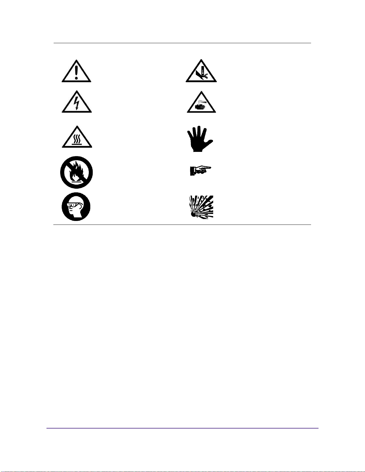
Important Symbols
WARNING! INJURY OR EVEN
DEATH MAY RESULT IF A
RECOMMENDATION MARKED
WITH THIS SYMBOL IS NOT
HEEDED.
CRUSH HAZARD. KEEP HANDS
CLEAR WHEN OPERATING DOOR.
ELECTRIC SHOCK DANGER!
USE APPROPRIATE CAUTION
TO AVOID INJURY OR DEATH.
CORROSIVE CHEMICAL. WEAR
SUITABLE GLOVES, SAFETY
GLASSES, AND PROTECTIVE
CLOTHING.
BURN DANGER! POTENTIALLY
HOT SURFACE. USE
APPROPRIATE CAUTION.
PROPERTY CAUTION! TO PREVENT
DAMAGE TO CHAMBER EQUIP-
MENT AND/OR LOAD, ADHERE TO
PROCEDURES MARKED BY THIS
SYMBOL.
DO NOT STORE FLAMMABLE
MATERIALS IN CHAMBER.
PRACTICAL OPERATING TIP.
THESE RECOMMENDATIONS
STREAMLINE UNIT OPERATION
AND PREVENT COMMON
OPERATOR ERRORS.
WEAR SAFETY GLASSES.
EXPLOSIVE MATERIALS HAZARD!
KEEP OBJECTS AWAY FROM HEAT.
Safety Warnings
Always transport the unit with care. Sudden jolts or drops may damage the refrigeration system.
Always observe all warning labels.
Always turn off the unit and disconnect the line cord from the available power source prior to performing anyservice or maintenance procedures.
Always turn off the unit and disconnect the line cord from the available power source prior to moving the unit.
Never operate equipment with damaged line cords.
Never remove warning labels.
Never operate damaged or leaking equipment.

Rev 007, 04/12 iii
© SP Scientific 2012
Warranty Information
FTS Systems Titan-Trap™ cold traps are warranted by SP Scientific to be free of defects in material and workmanship
when operated under normal conditions as specified in the instructions provided in this manual. Please take this
opportunity to locate the serial tag on your new FTS Systems Titan-Trap™ and record the information below for future
reference. SP Scientific also recommends that you complete and return your unit’s warranty registration card.
Model Number
Serial Number
Part Number
Limited Warranty
SP Scientific (the “Company”) shall warrant each of its products against defects in material or workmanship for a period
of 12 months from the date of shipment provided that the product is used in a reasonable manner under appropriate
conditions and consistent with the applicable operating instructions.
The obligation of the Company shall be, at its option, to repair or replace, without charge any parts that prove to be
defective within the warranty period, if the purchaser notifies the Company promptly in writing of such defect. No
product shall be returned to the Company without prior approval of the Company.
This limited warranty shall cover the costs of parts and labor to repair or replace all defective product(s) at the Seller’s
factory. For all products installed by the Company and located within the Company service travel areas, this warranty
shall cover transportation charges to ship the product to and from the Company’s factory and/or the costs of travel,
room and board if the Company’s employees conduct repair at the Buyer’s location. In lieu of repair or replacement at
the Company’s factory, the Company may, in its discretion, authorize a third party to perform the repair or replacement
at the Buyer’s location, and at the Company’s sole expense.
The Company shall not be responsible for labor charges payable with respect to persons other than Company
employees. Replacement or repair of parts pursuant to this warranty shall not in any way extend the original warranty
period. The Company shall not be responsible for any unauthorized repairs, replacements or product modifications, nor
will it be responsible for any product failures resulting from such unauthorized repairs, replacements or product
modifications negligently or otherwise made by persons other than Company employees or authorized representatives
of the Company. The buyer shall assume transportation charges to ship the product to and from the Company’s factory
and the costs of travel, room and board if the Company’s employees conduct repair at the Buyer’s location within the
warranty period if the product was not installed by the Company’s and/or is not located within the Company’s service
travel areas.
THE COMPANY DOES NOT MAKE AND EXPRESSLY DISCLAIMS ANY WARRANTY OF MERCHANTABILITY OR
FITNESS FOR A PARTICULAR PURPOSE OR ANY OTHER WARRANTY, EXPRESSED OR IMPLIED, WITH
RESPECT TO THE SALE, INSTALLATION, DESIGN OR USE OF ITS PRODUCTS. ADDITIONALLY, THE
COMPANY SHALL NOT BE LIABLE FOR ANY CONSEQUENTIAL DAMAGES RESULTING FROM THE USE OF OR
ANY DEFECTS IN ITS PRODUCTS.
The Company’s employees are available to provide general advice to customers concerning the use of the Company’s
products; however, oral representations are not warranties with respect to particular products or their uses and may not
be relied upon if they are inconsistent with the relevant product specifications for the items set forth herein.
Notwithstanding the above, the terms and conditions set forth in the Company’s formal sales contracts shall be
controlling and supersede any inconsistent terms contained herein, and any changes to such contracts must be made
in writing and signed by an authorized executive of the Company.
WARNING! THE DISPOSAL AND/OR EMISSION OF SUBSTANCES USED IN CONNECTION WITH
THIS EQUIPMENT MAY BE GOVERNED BY VARIOUS FEDERAL, STATE OR LOCAL
REGULATIONS. ALL USERS OF THIS EQUIPMENT ARE URGED TO BECOME FAMILIAR WITH
ANY REGULATIONS THAT APPLY IN THE USERS AREA CONCERNING THE DUMPING OF
WASTE MATERIALS IN OR UPON WATER, LAND OR AIR AND TO COMPLY WITH SUCH
REGULATIONS.

iv Rev 007, 04/12
© SP Scientific 2012

Rev 007, 04/12 v
© SP Scientific 2012
Contents
Important Symbols...............................................................................................................................................ii
Safety Warnings................................................................................................................................................... ii
Warranty Information .......................................................................................................................................... iii
Introduction .................................................................................................................1
Overview..............................................................................................................................................................1
Key Features...................................................................................................................................................1
Installation and Startup ...............................................................................................3
Initial Inspection...................................................................................................................................................3
Setup ...................................................................................................................................................................4
Service Connections .......................................................................................................................................4
Vacuum Pump Installation...............................................................................................................................4
Titan-Trap Installation ..........................................................................................................................................4
Vacuum Filters.....................................................................................................................................................6
Operation....................................................................................................................7
Overview..............................................................................................................................................................7
Operating Instructions..........................................................................................................................................7
Maintenance ...............................................................................................................9
Overview..............................................................................................................................................................9
Vacuum System...................................................................................................................................................9
Vacuum Pump.................................................................................................................................................9
Secondary Traps (Optional) ..........................................................................................................................10
Vacuum Tubing and Gaskets........................................................................................................................11
Refrigeration System .........................................................................................................................................11
The Air-Cooled Condenser............................................................................................................................11
Compressors.................................................................................................................................................12
Appendix A: Troubleshooting....................................................................................13
Vacuum Problems..............................................................................................................................................13

Contents
FTS Systems Titan-Trap™
vi Rev 007, 04/12
© SP Scientific 2012

Rev 007, 04/12 1
© SP Scientific 2012
Chapter
1
Introduction
Overview The Titan-Trap is an ultra-efficient, mechanically refrigerated cold trap designed to
condense both corrosive and non-corrosive vapor streams within a vacuum system.
Utilizing a helical titanium condenser coil, the polytetrafluoroethylene (PTFE)-coated
condenser chamber is available in both 4- and 8-liter capacities.
Key Features
Extremely compact design.
Several CFC-free refrigeration options with temperatures as low as -100 °C.
Easy-to-use rocker switch controls.
Titanium coil and PTFE-coated stainless steel chamber.
Safety-coated glass dome top.
Note: SP Scientific builds each unit according to the options purchased. Review the
standard sections, as well as the relevant optional sections of this manual.

Introduction
FTS Systems Titan-Trap™
2 Rev 007, 04/12
© SP Scientific 2012

Rev 007, 04/12 3
© SP Scientific 2012
Chapter
2
Installation and Startup
Initial Inspection
Your FTS Systems Titan-Trap™ cold trap was carefully packed and thoroughly
inspected before leaving the SP Scientific factory. However, in the unlikely event that
shipping damage has occurred, retain all packing material and contact your freight
carrier immediately.
DO NOT ACCEPT DAMAGED SHIPMENTS FROM A CARRIER WITHOUT A SIGNED
NOTIFICATION OF DAMAGES.
Upon receiving your shipment, inspect all contents of your equipment for damage.
Uncrate and/or unwrap the unit. Carefully remove all packing material from the unit
and inspect for visible damage. Check packing material for small accessory items.
Inspect the inside of the unit and related parts for visible damage and leaks.
If concealed damage or loss is discovered, contact the freight carrier immediately.
1
Keep all contents, packing material and related paperwork intact until a written report
is obtained.
Note: SP Scientific will cooperate in the matter of collecting your claim, but is not responsible
for the collection or free replacement of the material. When possible, replacement parts will be
shipped and invoiced to you, making them a part of your claim.
1
“Concealed damage or loss”refers to damage or loss that does not become apparent until the merchandise has been
unpacked and inspected. Should damage or loss be discovered, you may make a written request for inspection by the carrier's
agent within 15 days of the delivery date. You may then file a claim with the freight carrier or SP Scientific, depending on the
terms of your shipment. If your shipment was “FOB Destination” file your claim with SP Scientific and include the inspection
report and any other supporting documents. If your shipment was “FOB Shipping Point” file your claim with the freight carrier
and include the inspection report and any other supporting documents.
Installation and Startup
FTS Systems Titan-Trap™
4 Rev 007, 04/12
© SP Scientific 2012
Setup
NEVER PLACE THE UNIT IN AN AREA WHERE EXCESSIVE HEAT, MOISTURE OR CORROSIVE
MATERIALS ARE PRESENT.
The FTS Systems Titan-Trap™ is designed for installation in a laboratory
environment. The unit should be installed on a firm, level surface in a location that is
convenient for both operation and service.
Service Connections
CAUTION! IF YOU ARE UNSURE ABOUT THE AVAILABLE ELECTRICAL VOLTAGE SUPPLY IN
YOUR FACILITY, CONSULT A QUALIFIED ELECTRICIAN.
Make sure that the outlet you intend to use meets the voltage and amperage
requirements listed on the serial tag of your unit. Plug your Titan-Trap into an
appropriate outlet and switch on the circuit breaker only after following the installation
instructions in the following sections.
Note: SP Scientific ships domestic units with typical power connectors. International units are
shipped without a plug. In either instance, if your outlet configuration requires a different
connector, replace the plug according to local, state and/or national electric codes.
Vacuum Pump Installation
A remotely mounted vacuum pump (sold separately) is required for operation. The
vacuum pump should not exceed 250 liters/minute pumping capacity. The vacuum
pump should also be equipped with a vacuum brake solenoid (VBS) valve.
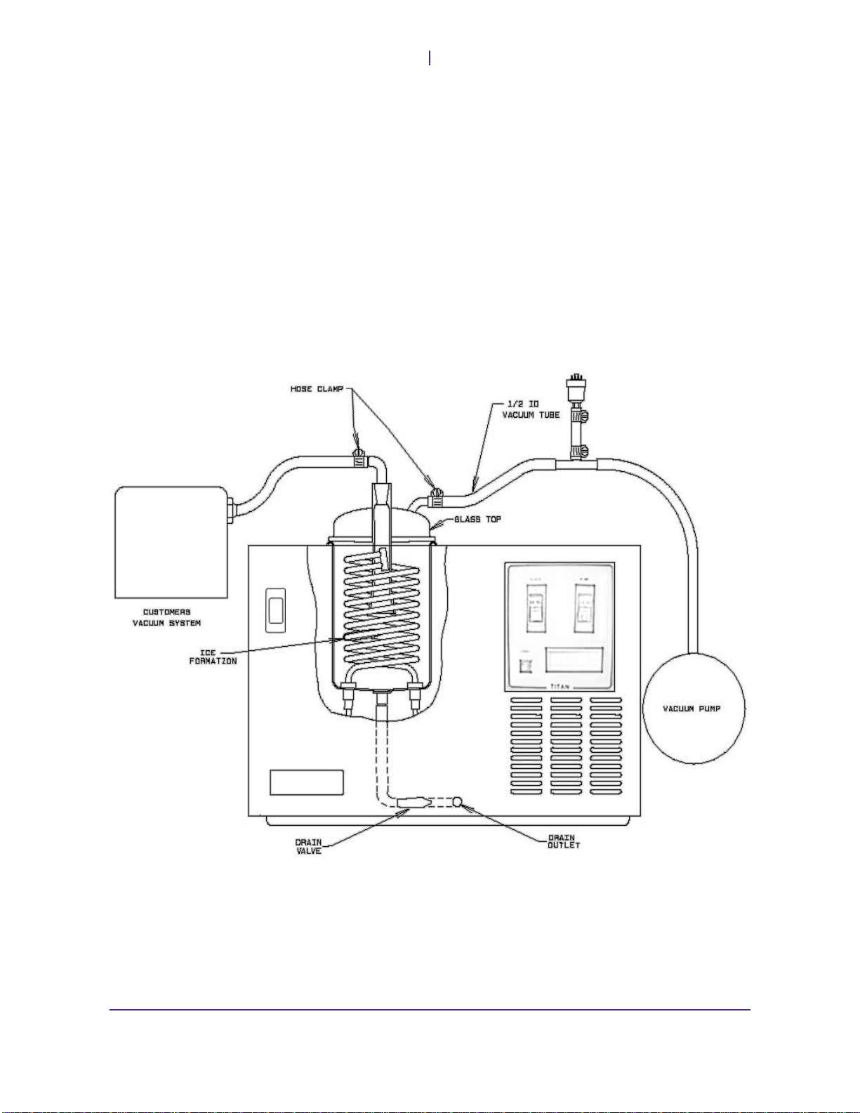
Titan-Trap Installation
Note: If you are installing a previously used vacuum pump, refer to Chapter 4: Maintenance
prior to installation.
Position the Titan-Trap in a convenient location near your process system and1. any other system components. The Titan-Trap should have a clearance of at
least 6 inches around all sides of the unit.
Locate the inlet port on your vacuum pump and remove any material with the2. exception of the inlet filter screen and gasket.
Remove all objects from the vacuum pump outlet port, but retain for future3. use.
Position the vacuum pump near the Titan-Trap. Ensure that the pump will be4. easily accessible during routine maintenance.
Place the adapter on the inlet port and secure with a fitting. If an adapter is5. not present, contact SP Scientific.
Using 1/2-inch ID vacuum tubing, connect the vacuum pump to the port on6. the side of the Titan-Trap’s glass dome. Secure the connection with a hose
clamp.
FTS Systems Titan-Trap™
Installation and Startup
Rev 007, 04/12 5
© SP Scientific 2012
Connect your process system to the 1/2-inch fitting on top of the glass dome
7. using an appropriate length of vacuum tubing. Secure the connection with a
hose clamp. If your process system utilizes a connection with a different fitting
size, you will need to procure an appropriate adapter.
Apply a thin coating of vacuum grease to the gasket on top of the Titan-Trap,8. if necessary, and install the glass dome into the gasket.
Plug the vacuum pump into the standard receptacle marked VACUUM PUMP9. on the back of the unit. The voltage, phase and frequency of the vacuum
pump must match the voltage, phase and frequency specified on the rear
panel of the Titan-Trap.
Check the vacuum pump oil level. The oil level should read midway up the10. sight glass. Add oil only if necessary. DO NOT OVERFILL.
Plug the Titan-Trap into an appropriate outlet and turn on the unit.11.

Installation and Startup
FTS Systems Titan-Trap™
6 Rev 007, 04/12
© SP Scientific 2012
Vacuum Filters
SP Scientific suggests that you install an Oil Mist Eliminator (OME) to reduce fumes
exhausted by the vacuum pump. If an OME is not available, vent the vacuum exhaust
externally.
Additionally, vacuum filter traps are available for installation between the vacuum
pump and the Titan-Trap unit. These filters help protect vacuum pump oil from
solvents and vapors not trapped by the condenser. See the section entitled
Secondary Traps in Chapter 4: Maintenance for more information.

Rev 007, 04/12 7
© SP Scientific 2012
Chapter
3
Operation
Overview Your Titan-Trap is equipped with a panel of rocker switches and a digital display for
ease of use.
Note: Prior to operating your Titan-Trap, ensure that the condenser chamber and coil are clean
and dry.
Operating Instructions
WARNING: IT IS IMPORTANT TO UNDERSTAND THE PROPERTIES OF YOUR CONDENSATE. IF
CONDENSING VOLATILE OR OTHERWISE HAZARDOUS SUBSTANCES, TAKE THE PROPER
HANDLING PRECAUTIONS. DO NOT USE HOT WATER TO DEFROST THE CONDENSER IF THE
ADDITION OF WATER WILL CAUSE ANY TYPE OF CHEMICAL REACTION. DISPOSE OF ALL
HAZARDOUS CHEMICALS IN ACCORDANCE WITH LOCAL, STATE AND NATIONAL REGULATIONS.
Ensure that the drain valve on the front of the unit is in the closed position.1.
Check that all connections are secure.2.
Enable power to the unit by toggling the rocker switch labeled Power to the3. ON position.
The refrigeration system will begin operation automatically. If your unit is4. equipped with a single-stage refrigeration system, the Cool indicator LED will
illuminate immediately, signifying that the refrigeration system has begun
cooling the condenser coil.
If your unit is equipped with a cascade refrigeration system, the Cool indicator
LED will not illuminate until the first-stage compressor reaches the proper
operating temperature. Once the first-stage compressor reaches operating
temperature, second-stage compressor cooling will begin. The second-stage
compressor will energize automatically to begin cooling the condenser coil
and the Cool LED will then illuminate.
Allow the refrigeration system to cool the trap to an appropriate temperature.5.
Enable vacuum by toggling the Pump rocker switch to the On position and6. allow the system to evacuate.
Note: If your vacuum pump is not connected to your Titan-Trap via the receptacle on
the rear of unit, toggling the rocker switch on your unit cannot enable it. You must
switch on the vacuum pump manually. See your vacuum pump operator’s manual for
more information.
When the Titan-Trap has reached operating temperature and vacuum, enable7. your process system as required. For example, if you are using a vacuum
concentrator, begin spinning your samples.
Observe your product to determine when your process is complete.8.

Operation
FTS Systems Titan-Trap™
8 Rev 007, 04/12
© SP Scientific 2012
Switch off the vacuum and refrigeration systems using the rocker switches on
9. the front panel of the Titan-Trap unit.
Release vacuum by opening the drain plug on the front of the Titan-Trap or10. the Vacuum Release Valve, if equipped.
After removing all product from your process, your Titan-Trap must be11. defrosted.
Connect a drain line to the valve on the front of the unit and route the tubing
to an appropriate condensate collection vessel. If the drain valve is not
already open, turn the handle to the horizontal position and allow the
condensate to melt and drain.
Defrosting may be expedited by adding hot water to the trap. Close the drain
valve, remove the glass dome and add water directly to the condenser
chamber. Do not allow the water level to reach the gasket that seals the glass
dome. After allowing the water ample time to melt the condensate, open the
drain valve and allow the condenser to drain. Repeat as necessary.
Once all of the condensate has melted and drained into the collection vessel,12. thoroughly clean and rinse the condenser with a mild detergent or baking
soda solution (to neutralize acids). Thoroughly dry the chamber and coil.
Note: Do not chip away at the ice, as this may damage the condenser.
Replace the glass dome and close the drain valve on the front of the Titan-13. Trap.

Rev 007, 04/12 9
© SP Scientific 2012
Chapter
4
Maintenance
Overview
ALWAYS REMOVE POWER FROM THE UNIT BEFORE PERFORMING MAINTENANCE
PROCEDURES.
ALWAYS NOTIFY THE SP SCIENTIFIC SERVICE DEPARTMENT BEFORE PERFORMING
REPAIRS TO A UNIT THAT IS UNDER WARRANTY. FAILURE TO NOTIFY SP SCIENTIFIC
SERVICE WILL VOID THE FACTORY WARRANTY.
Proper routine maintenance is the key to an efficiently operating unit with minimal
downtime. The following section provides instructions on how to maintain your Titan-
Trap.
Vacuum System
Vacuum Pump
PROPERTY CAUTION! IF YOUR PRODUCT CONTAINS CORROSIVE MATERIALS OR ORGANIC
SOLVENTS, OIL MUST BE CHECKED AND CHANGED MORE OFTEN. IN ADDITION, A FILTER
TRAP MAY BE INSTALLED TO PROTECT THE VACUUM PUMP.
Clean oil is necessary for the best vacuum and overall efficiency of the system.
Checking and changing the oil on a consistent basis will greatly extend the life of the
vacuum pump.
Check the vacuum pump oil after each use by draining a small amount (~100 mL)
from the pump drain line. Use a clear container to capture the sample and compare it
to a sample of clean, unused vacuum oil. Oil should be changed as needed.
When visually checking the oil, use the following guidelines:
Pale yellow or clear vacuum pump oil indicates good condition.
Dark vacuum pump oil indicates acid contamination.
Cloudy gray vacuum pump oil indicates water contamination.

Maintenance
FTS Systems Titan-Trap™
10 Rev 007, 04/12
© SP Scientific 2012
Changing Vacuum Pump Oil
Periodically wipe down the exterior of the bath, including stainless steel components,
using a soft cloth and mild soap solution. Do not use steel wool as it may lead to
rusting of the exterior components. Dry the bath using a soft, dry cloth.
Change the oil immediately after shutting down the pump while the oil is still hot. To
change vacuum pump oil:
Protect your hands from the hot oil.1.
Make sure that vacuum is released from the system.2.
Remove the top fill plug and open the drain valve located at the bottom of the3. pump. Drain the contaminated oil into a suitable container.
When the oil has completely drained, close the valve and add new oil to the4. pump while visually checking the sight glass to ensure proper level (near the
MAX line). Reinstall the fill plug.
If pump oil is particularly contaminated, operate the vacuum pump for 10 to155. minutes to flush any residual oil from the system’s interior components.
Repeat steps 3 and 4 to complete the process.
Scheduling Oil Changes
After clean oil is loaded into the vacuum pump and all necessary connections have
been made between the vacuum pump and the Titan-Trap, perform a full capacity test
cycle.
Have a qualified technician check the oil after the test cycle. If the oil appears dirty,
change the oil after every use. If the used oil appears clean, change the oil after the
next two uses or cycles. If the oil remains clean after two cycles, change the oil after
the next four cycles. Continue to monitor the vacuum pump oil after each use until a
change of condition is noted or a period of one month has elapsed. If the oil remains
clean after several uses, changing the oil once per month may be sufficient.
Secondary Traps (Optional)
Most aqueous-based products will completely condense or trap on the condenser.
However, products that contain elements with freezing points near or below the
operational temperature of the condenser coil may bypass the condenser and trap in
the vacuum pump instead. The result can be severely reduced vacuum performance
and/or failure.
Optional secondary traps are available for acid and solvent product applications
where vapors may bypass the condenser and extra protection is required for the
vacuum pump.
There are two types of cartridges—a Sodasorb cartridge for acid-based applications
and an activated charcoal cartridge for solvent-based applications. The Sodasorb
cartridge has an indicator that will change to a blue color when replacement is
required. The activated charcoal cartridge contains no indicator, so replacement is
best done at regular intervals. Depending on the usage and concentration, changing
the charcoal cartridge every three to six months may suffice.

FTS Systems Titan-Trap™
Maintenance
Rev 007, 04/12 11
© SP Scientific 2012
Vacuum Tubing and Gaskets
Inspect tubing and gaskets periodically for signs of wear (i.e., cracking or dried
appearance). Check gaskets by removing and inspecting interior surfaces for potential
problems. A light coating of vacuum grease on the exterior surfaces will protect
gaskets and tubing. Reapply grease as needed.
Refrigeration System
The Air-Cooled Condenser
It is very important to keep the air-cooled condenser clean. This is where high-
pressure vapor from the compressor is converted to liquid refrigerant by rejecting the
heat gained from the vapor condenser into the ambient air. Reduced airflow over the
condenser can result in severely reduced performance and may shorten the life of the
compressor.
To maintain the air-cooled condenser and compressor:
Remove the unit’s metal wrapper and vacuum the condenser fins.1.
Always maintain at least six inches of clearance around all sides of the unit.2.
Always maintain a room temperature approximately 20 °C. Higher3. temperatures may result in reduced performance and shorten the life of the
compressor.
Inspect the fan for proper operation:4.
Place your hand in front of the louvers. You should feel warm aira. being gently exhausted.
Place a paper towel in front of the intake louvers under the controlb. panel. A properly operating fan will pull in enough air to hold the
paper towel in place.
If problems persist, contact SP Scientific Service.

Maintenance
FTS Systems Titan-Trap™
12 Rev 007, 04/12
© SP Scientific 2012
Compressors
Your Titan-Trap contains two compressors.
When a cooling problem is suspected, have a qualified refrigeration service technician
check the refrigerant charge or contact SP Scientific Service. Each refrigeration
system contains a specified charge. This charge is listed on a black charge tag
attached to the back of the unit. The charge tag indicates the refrigerant type and
static pressure.
A qualified refrigeration technician may check the charge after the unit has been off
for several hours at room temperature. This will allow the internal pressures to
equalize. The shroud will need to be removed to allow the Hi and Lo side access
valves to be visible. If the actual system pressure matches the pressure specified on
the charge tag ±5 percent, a refrigeration leak may be ruled out. If the actual system
pressure is less than 5 percent of the specified charge, it may be necessary to leak
check the system and repair the leak.
If a refrigeration problem is suspected, a qualified technician should check for frost on
the suction line. If the line is warm or just slightly cool to the touch, it usually means
that a loss of refrigerant has occurred, and that the condenser and shelf are
experiencing cooling problems. Contact SP Scientific for more information.
This manual suits for next models
1
Table of contents
Other SP Scientific Laboratory Equipment manuals


Popular Laboratory Equipment manuals by other brands

Safe Fleet
Safe Fleet FoamPRO AccuMax 3020 Installation and operation manual

Scientific Industries
Scientific Industries Vortex-Genie 2 Series operating instructions

Viso Systems
Viso Systems LabTarget user manual

Mind Peak
Mind Peak WaveRider operating manual

Sonel
Sonel KT-165 user manual

Applied Biosystems
Applied Biosystems 7900HT user guide


