PLC 2450 User manual

PLC-2450 interface guide
Main screen display
•DC LD Volts is the voltage applied to the load
•CH LD AMPS is the current the load is using
•BAT CH AMPS is the current used to charge the batteries
•BAT LD AMPS is the current from the batteries to the load
•The flashing * is the heatbeat indicating program is running
STATUS pushbutton will move to the alarm and relay status screen.
RESET pushbutton will reset alarms when fault condition clears when pushed from the
main screen or the status screen

STATUS SCREEN
Alarm and Status for
•AC – AC circuit feeding the charger either OK or FAIL
•DC – DC volts is above the Low Voltage Setpoint either OK or FAIL
•CHRG – Charger is running and carrying the load either OK or FAIL
•TEMP – Charger cooling fans are running either OK or FAIL
•PCB *– Status of the 5 Power Control Modules 1=OK, 0=FAULT
•Relays – Alarm relays are on=1 or off=0
Alarms are reset by pushing the green RESET pushbutton
To move to the DC LOW Volts SetPT screen, press the green RESET and the yellow
STATUS pushbutton simultaneously. Other wise the status screen will display for
approximately 10 seconds, then return to the MAIN screen.
*The PCB’s are internally interconnected to monitor the output voltage of each module,
and share the load. The deviation is .5 VDC, and is factory set. It is not uncommon to
see the status of one or more modules change from 1 to 0 under small load conditions.
Each PCB can deliver 10 amps of current. If a PCB remains a 0 under near full load
conditions (50A) consult Prologic for assistance.

DC Low Volts SetPT SCREEN
To select the DC Low Volts setpoint, press the yellow STATUS pushbutton to cycle
through the preset voltages. The * indicates the selected voltage. When the desired
voltage setpoint is selected, press the green RESET pushbutton to store the setting to
eeprom and return to the MAIN screen. If the RESET pushbutton is not pressed, the
selection will not be stored.This screen will automatically return to the MAIN screen in
approximately 10 seconds if the RESET pushbutton is not pressed.
Note Default setpoint is 21.50 V
Wiring Connections
Temp – N.O. contact .5A 24VDC
RECT – N.O. contact .5A 24VDC
LODC – N.O. contact .5A 24VDC
ACFL – N.O. contact .5A 24VDC
BATT+CT- Current transmitter for Battery current
LOAD+CT- Current transmitter for Load current
VOLTS +AO- Optional analog output 4-20ma scaled 0-30V
AMPS +AO- Optional analog output for load current 4-20ma scaled 0-50A
Note – All terminations are completed by Prologic to field wiring terminal strip in the
charger panel.

Operating Manual
•Provides N+1 redundancy
•Expand output power by adding power Modules
•Up to 50 amps continuous power
BATTERY BACK-UP / CHARGING FUNCTION
PLC
PLCPLC
PLC-
--
-2450
24502450
2450
Power supply/Battery charger
Power supply/Battery chargerPower supply/Battery charger
Power supply/Battery charger

DESCRIPTION
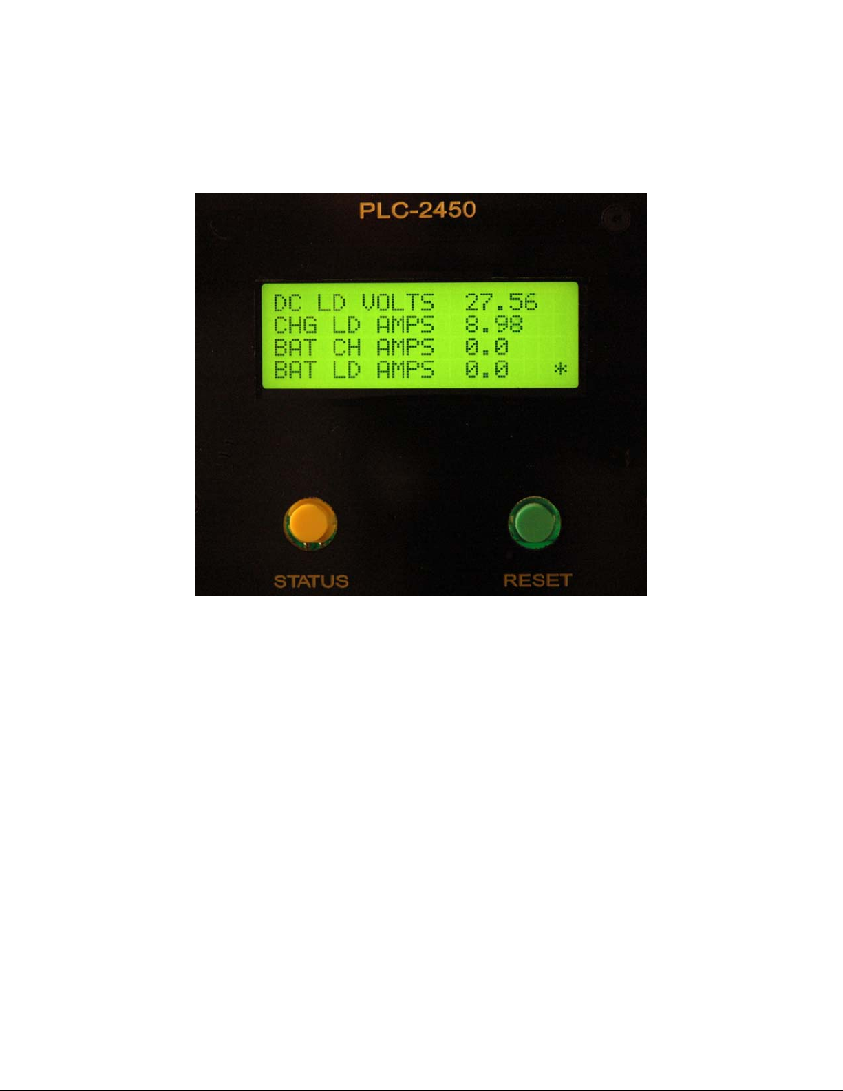
This Power Supply converts 120 V , 60 Hz. AC power into tightly regu-
lated 27.6 V DC , +/- 1% delivering up to a maximum of 50 A continuous
( up to 55 A surge ) with 5 Base Level PCB Modules.
APPLICATIONS
The unit is designed for the following applications :
1. Critical power supply application requiring uninterrupted battery
back-up supply.
2. Telecommunication, Audio Display, GPS receiving stations, PLC
or RTU installation.
DESIGN AND PRINCIPLE OF OPERATION
The unit is designed using advanced switch mode technology and load
share circuitry for high reliability, high efficiency and minimum size and
weight. It is modular in construction consisting of up to 5 Base Level PCB
Modules ( referred to as PSM “POWER SUPPLY MODULES” ) that are
connected for parallel operation with true current sharing . Each module
is a stand alone power supply which delivers up to a maximum of 10 A
continuous ( 11A surge) . By equalizing the output currents, uniform ther-
mal stress of the individual modules is also ensured which has utmost
importance for long term reliability of electronic components. The oper-
ating principle of the load share mechanism is to measure the output cur-
rent of each individual module and to be able to modify the output voltage
of the units until all the participating modules deliver equal output cur-
rents. Each module is required to be inter-connected with each other to a
common “SHARE BUS” through a pair of parallel pins marked “JUMP1”
and jumper wires. Typically, the output currents for the paralleled units
will be within 10% of each other at full output current.
COOLING AND WARNING FOR FAN FAILURE
The heat generated due to internal power dissipation is removed by
forced cooling through two high power D.C. fans mounted at the back of
the unit which blow air from the outside into the unit. The forced air is ex-
hausted out through the vent holes provided on the two sides of the unit.
IT IS EXTREMELY IMPORTANT THAT THE SUCTION SIDE OF THE
FANS AND THE DISCHARGE SIDES OF THE VENT HOLES ARE NOT
BLOCKED.
A warning circuit monitors the operational condition of the fans. In case of
fan failure, a buzzer will sound and the red LED indicating “TEMP.
FAULT” will light up. The unit should be switched off immediately and the
defective fan should be replaced. NEVER LOAD THE UNIT WHEN
THERE IS AN AUDIBLE ALARM AND THE TEMP. FAULT L.E.D IS
ILLUMINATED. 1.

S1
LED 1
JUMP 1
S-5
S-6
S2
N
L
S4
M-20
Figure 1 - Layout of Power Supply Module
S1 to S4 Holes for 4 screws to fasten the module to the chassis
S5 & S6 Holes for 2 screw to connect to the Positive and Negative output BUS Bars.
L & N L ( live ) and N ( neutral ) terminals for 120V, 60 Hz input power supply wires
LED 1 Terminal for connecting L.E.D. “ PCB Status “
JUMP 1 Jumper terminal for connecting share BUS wire
2.
Figure 1.
S3

PROTECTIONS
SHORT CIRCUIT PROTECTION : In the event of a short circuit, the
PWM controller will be shut down and the output will drop to near 0 V.
The unit will automatically reset once the short circuit condition is removed.
CURRENT LIMITING : The unit will enter this mode when the load tries
to draw more than the limiting values of currents as shown in the specifi-
cations. Under this condition, there will be loss of voltage regulation and
the output voltage will drop. The “PCB STATUS” will, however, remain
a 0 . The unit will reset automatically as soon as the overload
condition is removed .
INPUT SURGE PROTECTION : The unit is protected against input volt-
age surges.
3.

FAN FAILURE WARNING INDICATOR AND ALARM : If forced air
cooling is stopped due to failure of any one or both the fans, the TEMP
FAULT will report FAIL and an audible alarm buzzer will be activated.
The unit is required to be switched off immediately as loss of forced air
cooling may result in major damage to the unit.
INSTALLATION AND OPERATION
1. Ensure that the space where the unit is to be installed has adequate
air supply for cooling. There should be no obstruction on the suction
side of the fans at the back or on the discharge side vent holes on the
two sides of the unit.
2. Switch off the on/off switch on the front panel.
3. Switch off all the D.C. load(s) to be connected to this unit.
4. Connect the positive and negative sides of the output at the back of
the unit to the D.C. load(s) or the DC bus. Ensure the wire or bus bar
used to connect the load or the D.C. bus is of proper cross-section to
carry the desired load current. Tighten the screws on the positive and
negative terminals to ensure firm connection.
5. Plug the unit into the 120 V, 60 Hz standard mains outlet . The out-
let should be rated for at least 20 A.
6. Switch on the unit by pressing the power on/off switch to on position.
The switch will be illuminated confirming that input power is available.
7. A beep will be generated by the temperature fault alarm circuit on
powering on the unit . This is normal. Please disregard.
8. Switch the volt/amp change-over switch to the “VOLT” position. The
voltmeter should read 27.6 V.
9. Switch on the D.C. loads. The output voltage should remain regu-
lated within 27.3 V to 27.6 V.
10. Switch the volt/amp meter switch to “AMP” position to read the load
current. Ensure that the load current is within the total rated continuous
load of the modules installed.
INSTALLATION AND REMOVAL OF POWER SUPPLY MODULES
NOTE :
INSTALLATION AND REMOVAL OF POWER SUPPLY MODULES
SHOULD BE PERFORMED ONLY BY QUALIFIED PERSONNEL.
CAUTION !
Before removing a defective module or installing a new one, switch off
the 120 V , 60 Hz input power and unplug the power cord from the
mains outlet.
NOTE : Please refer to the layout diagram of the module at Figure. 1
located on page 2.
4.

SPECIFICATIONS
NO. OF MODULES 5
INPUT VOLTAGE RANGE 105 TO 125 V AC, 60 HZ
OUTPUT VOLTAGE 27.6 V DC
OUTPUT REGULATION 1%
OUTPUT CURRENT
CONTINUOUS 50 A
SURGE 55 A
OUTPUT CURRENT LIMIT 60 A
OUTPUT RIPPLE 60 mV
OUTPUT NOISE UPTO 600 mV
COOLING FORCED AIR, 2 FANS
OPERATING TEMPERATURE 0 TO 40 C
PROTECTIONS
- SHORT CIRCUIT YES
- FAN FAILURE LED AND BUZZER
- INPUT SURGE
SUPRESSION YES
- FUSE MODULE FUSE – 125V 4 A
UNIT HAS SWITCH / BREAKER
125 V, 20 A
DIMENSIONS 19” X 14” X 3.6”
WEIGHT, LBS 23
5.
Table of contents