manuals.online logo
Brands
  1. Home
  2. •
  3. Brands
  4. •
  5. Emerson
  6. •
  7. Control Unit
  8. •
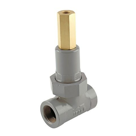
  9. Emerson ALCO Thermo TX6 User manual

Emerson ALCO Thermo TX6 User manual

Document Nr.: A6.5.012 Rev 02 Replacement for A6.5.012 Rev 01 Date: 22.08.2005 DWG Nr.: TX6EA001000/PCN 861519
GB
Installation Instructions
Thermo®-Expansion Valve
TX6 D
Einbauanleitung
Thermo®-Expansionsventil
TX6 NL
Montagevoorschrift
Thermo®Expansieventiel
TX6
ALCO CONTROLS
Emerson Electric GmbH & Co OHG
Heerstr.111 - D 71332 Waiblingen
Tel.: -49(0)7151 509-0 - Fax.: -200
www.ecopeland.com/alcoliterature.cfm
Fig. 1:
Fig. 2:
General information and technical data
ALCO’s TX6 series of Thermo-Expansion Valves are
designed for air conditioning, chillers, rooftops, close
control, A/C transportation, heat pumps and industrial
cooling process applications. TX6 with suitable charges for
the following refrigerants:
Refrigerant Type of valve
R22: TX6-H…
R134a: TX6-M…
R407C: TX6-N…
R410A: TX6-Z..
Fluid temperature range: –40°C .. +120°C
Fluid group: II
Refrigerants: CFC, HCFC, HFC
Maximum working pressure PS:
TX6-H/M/N: 31bar
TX6-Z: 42bar
Hazard category: TX6-H/M/N: not allowed
(PED 97/23/EC) TX6-Z_2/3/4/5: not allowed
TX6-Z_6/7 I
CE Marking: TX6-H/M/N: not applicable
TX6-Z_2/3/4/5: not applicable
TX6-Z_6/7: yes
Connection DN: see Fig. 1
!Safety instructions
Read installation instruction thoroughly. Failure to comply
can result in device failure, system damage or personal
injury.
Before opening any system make sure pressure in system is
brought to and remains at atmospheric pressure.
Do not use any other fluid media without prior approval of
ALCO Controls. Use of fluid not listed could result in:
Change of hazard category of product and consequently
change of conformity assessment requirement for product
in accordance with European pressure equipment directive
97/23/EC.
Installation (Fig. 1, 2, 3, 4)
1. Valves may be installed in any position, but should be
located as close as possible to the distributor or evaporator
inlet.
2. Be sure liquid line is connected to inlet of TX6 (marked
"IN" on valve body).
3. Install line connections to valve. Wrap wet cloths
around the valve to prevent valve damage while brazing.
Direct torch away from valve (max. temp. see Fig. 1).
4. Securely fasten the bulb with straps provided. Insulate
bulb with a suitable material.
5. In heat pump applications/systems, connect the external
equalizer tube from valve to main suction line between
reversing valve and suction accumulator (if available) or
compressor and locate the bulb of TX6 nearby as shown in
Fig.2.
6. The location of bulb on suction line is de
p
endant to size
Allgemeines und Technische Daten
Die Baureihe TX6 wurde für die besonderen Erfordernisse
von Klimaanwendungen, Kaltwassersätzen, Transport-
klima, Wärmepumpen, Industriekühlung und sonstigen
Kälteanwendungen entwickelt. TX6 gibt es mit passenden
Füllungen für folgende Kältemittel:
Kältemittel Ventiltyp
R22: TX6-H…
R134a: TX6-M…
R407C: TX6-N…
R410A: TX6-Z..
Fühlertemperaturbereich: –40°C .. +120°C
Fluidgruppe: II
Kältemittel: CFC, HCFC, HFC
Max. Betriebsüberdruck PS:
TX6-H/M/N: 31bar
TX6-Z: 42bar
Konformitäts- TX6-H/M/N: nicht zulässig
bewertungskategorie: TX6-Z_2/3/4/5: nicht zulässig
(PED 97/23/EC) TX6-Z_6/7 I
CE Kennzeichnung: TX6-H/M/N: nicht erforderl.
TX6-Z_2/3/4/5: nicht erforderl.
TX6-Z_6/7: ja
Anschlüsse DN: siehe Fig. 1
!Sicherheitshinweise
Lesen Sie bitte die Einbauanleitung gründlich. Nicht-
beachtung kann zum Versagen oder zur Zerstörung des
Ventiles und zu Verletzungen führen.
Vor dem Öffnen des Kältekreislaufes ist darauf zu
achten, daß der Druck im System gleich dem atmos-
phärischen Druck ist und verbleibt.
Es dürfen nur von Alco Controls freigegebene
Kältemittel eingesetzt werden. Die Verwendung nicht
freigegebener Medien kann die Gefahrenkategorie und
das erforderliche Konformitätsbewertungsverfahren für
das Produkt gemäß Europäischer Druckgeräterichtlinie
97/23/EG verändern.
Einbau (Fig. 1, 2, 3, 4)
1. Das Ventil kann in beliebiger Einbaulage installiert
werden, sollte jedoch möglichst nahe am Verdampfer bzw.
Verteilereintritt platziert werden (siehe Fig.2).
2. Achten Sie darauf, daß die Flüssigkeitsleitung mit dem
Eintritt des TX 6 verbunden wird (Markierung "IN" am
Ventilkörper).
3. Verbinden Sie die Anschlüsse des Expansionsventiles.
Wickeln Sie vor dem Lötvorgang einen nassen Lappen um
das Ventil, um es vor übermäßiger Hitze zu schützen. Die
Lötflamme nicht gegen das Ventil richten (max.
Temperaturen s. Fig. 1).
4. Befestigen Sie den Fühler mit den Fühlerschellen (Fig.
3) möglichst nahe am Verdampferaustritt und sorgen Sie
für eine gute Isolierung des Fühlers.
5. In Wärmepumpen ist der externe Druckausgleich vom
Algemene en Technische gegevens
De TX6 van ALCO zijn ontworpen voor toepassing in
air conditioning, chillers, rooftops, close control, A/C
transport, warmtepompen, en industriële koeltechnische
toepassingen. TX6 zijn beschikbaar met vullingen voor
de volgende koudemiddelen:
Koudemiddel Ventiel-type
R22: TX6-H…
R134a: TX6-M…
R407C: TX6-N…
R410A: TX6-Z..
Mediumtemperatuur: –40°C .. +120°C
Mediumklasse: II
Koudemiddelen: CFK, HCFK, HFK
Max. bedrijfsoverdruk PS:
TX6-H/M/N: 31bar
TX6-Z: 42bar
Gevaren klasse: TX6-H/M/N: niet toegestaan
(PED 97/23/EC)TX6-Z_2/3/4/5: niet toegestaan
TX6-Z_6/7 I
CE Markering: TX6-H/M/N: niet van toepassing
TX6-Z_2/3/4/5: niet van toepassing
TX6-Z_6/7: ja
Aansluitingen DN: zie Fig. 1
!Veiligheidsinstrukties
Lees de montagevoorschriften zorgvuldig door. Het
niet opvolgen van de montagevoorschriften kan falen
van het ventiel, beschadiging van het ventiel en/of
verwondingen veroorzaken.
Voor het openen van het koelsysteem dient het
koelsysteem drukloos te worden gemaakt en dient te
zijn zekergesteld dat het koelsysteem drukloos blijft.
Geen gebruik geen andere media zonder vooraf-
gaande toestemming van ALCO. Het gebruik van
enig ander media dan de aangegeven media kan
resulteren in een wijziging in de gevarenklasse van
het product en dientengevolge een wijziging in de
benodigde conformiteits assessments voor het
product in overeenstemming met het Europese
drukvaten besluit (PED) 97/23/EC.
Inbouw (Fig. 1, 2, 3, 4)
1. Het ventiel kan in elke willekeurige stand worden
gemonteerd. Een inbouw zo dicht mogelijk voor de ver-
damper resp. de verdeler geniet de voorkeur (z.Fig. 2).
2. Verzeker u ervan dat de vloeistofleiding met de
intrede van van het TX6 verbonden wordt (gemarkeerd
met „IN“ op het huis).
3. Sluit de leidingen op het ventiel aan. Voor begin van
het solderen dient het ventiel ter bescherming tegen te
hoge temperaturen met een natte lap te worden
omwikkeld. De soldeervlam van het ventiel af gericht
houden (max. temperaturen zie Fig. 1).
4. Bevestig de voeler aan de zuigleiding (Fig. 3) zo
dicht mogelijk aan de verdamper uittrede. De voeler
max. 700°C max. 120°C
max. °C
MOP 120°C
M0 90°C
H0 75°C
S0 70°C
ODF
(1) (2) (3)
TX6-_ _ 2,3 1/2’’/ 12mm 5/8’’/ 16mm
TX6-_ _ 4,5 5/8’’/ 16mm 7/8’’/ 22mm 1/4’’/ 6mm
TX6-_ _ 6,7 7/8’’/ 22mm 1 1/8’’/ 28mm
Outdoor
coil
Indoor
coil
BFK
Bi-flow
Four way valve
Compressor
Accumulator
Check valve
Check valve
Document Nr.: A6.5.012 Rev 02 Replacement for A6.5.012 Rev 01 Date: 22.08.2005 DWG Nr.: TX6EA001000/PCN 861519
Fig. 3:
< 7/8’’ / 22 mm ∅≥7/8’’ / 22 mm ∅
Fig. 4:
Fig. 5:
P
T (°C) - T (°C) = sh (K)
PS
Fig. 6:
10°C 0°C -10°C -20°C -30°C -40°C
R 134a
TX6-_ _2, 3 1,2 1,6 2,1 2,8
TX6-_ _4, 5, 6, 7 1,9 2,5 3,3 4,5
R 22
TX6-_ _2, 3 0,8 1,0 1,3 1,7 2,3 3,3
TX6-_ _4, 5, 6, 7 1,3 1,7 2,1 2,8 3,7 5,1
R 410A
TX6-_ _2, 3 0.5 0.7 0.9 1,1 1,5 2,1
TX6-_ _4, 5, 6, 7 0.9 1,1 1,4 1,8 2,4 3,3
R 407C
TX6-_ _2, 3 0,8 1,0 1,4 1,9
TX6-_ _4, 5, 6, 7 1,3 1,7 2,2 3,0
of suction line (see Fig. 3)
7. Be sure that the external equalizer line cannot siphon
oil from the suction line.
8. The expansion valve must be free of all contaminants.
Install an ALCO Filter Drier before the valve.
9. Check for leaks, sufficient refrigerant charge and be
sure no flash gas is present before attempting to check
valve operation.
Leakage test:
After completion of installation, a test pressure must be
carried out as follows:
- According to EN378 for systems which must comply with
European pressure equipment directive 97/23/EC
- To maximum working pressure of system for other
applications
Proper operation of charges
The maximum bulb temperature is limited to the values
showed in Fig.1.
Warning: Valves with gas charge feature MOP
function and operate properly only if the temperature at
the bulb is below the temperature at the head of the
valve and at the capillary tube (see Fig. 4). If valve head
becomes colder than the bulb, malfunction of the
expansion valve occurs (i.e. erratic low pressure or
excessive superheat).
Superheat Adjustment (Fig. 5, 6)
The TX6 - Expansion Valve is factory set to a static
superheat of 3.3 K. If the superheat must be adjusted for
the application proceed as follows:
1. Remove seal cap from bottom of valve.
2. Turn the adjustment screw clockwise to increase the
superheat and counterclockwise to decrease superheat.
Changes in Superheat (K) per stem turn depending on
evaporating temperature and refrigerant see Fig. 6. As
much as 30 minutes are required for the system to stabilize
after the adjustment is made.
3. Determine superheat “sh” according to Fig. 5.
4. Replace and tighten seal cap.
Warning: There are max. 10 turns on the adjustment
stem (from left to right stop). When stop is reached any
further turning will damage the valve.
Ventil an der Saugleitung zwischen 4-Wegeventil und
Saugleitungssammler (sofern vorhanden) oder Verdichter
anzuschließen, die TX6 Fühlerpatrone daneben, siehe Fig. 2.
6. Die Position der Fühlerpatrone hängt vom Durchmesser
der Saugleitung ab, siehe Fig. 3.
7. Der externe Druckausgleich ist so zu montieren, daß
sich kein Öl aus der Saugleitung ansammeln kann.
8. Im Expansionsventil darf kein Schmutz sein. Vor dem
Ventil ist ein ALCO Filtertrockner zu montieren..
9. Vor dem Funktionstest des Ventils ist die Anlage auf
Dichtigkeit zu prüfen und sicherzustellen, daß sie
genügend Kältemittel ohne Flashgas enthält.
Dichtheitsprüfung:
Nach der Installation ist ein Drucktest durchzuführen:
– Gemäß EN378 für Geräte die die Europäische
Druckgeräterichtlinie 97/23/EC erfüllen sollen.
– Mit dem maximalen Betriebsüberdruck des Systems für
alle anderen Anwendungen.
Hinweise zur Funktion der Fühlerfüllungen
Es ist darauf zu achten, daß die maximalen Fühler-
temperaturen gemäß Fig. 1 nicht überschritten werden.
Achtung: Ventile mit Gasfüllung verfügen über eine
MOP Funktion und arbeiten nur dann zuverlässig,
wenn die Temperatur am Fühler unter der Temperatur
des Oberteils oder der Kapillarrohre liegt (siehe Fig. 4).
Wird das Oberteil kälter als der Fühler, tritt eine
Fehlfunktion des Ventils auf (z.B. sehr niedriger,
schwankender Druck oder sehr große Überhitzung).
Überhitzungseinstellung (Fig. 5, 6)
Das TX6 ist werkseitig auf eine statische Überhitzung
von 3,3 K eingestellt. Sollte es erforderlich sein die
Überhitzung zu verändern, gehen Sie wie folgt vor:
1. Entfernen Sie die Abdeckkappe unten am Ventil.
2. Durch drehen der Einstellspindel im Uhrzeigersinn wird
die Überhitzung vergrößert bzw. bei drehen entgegen dem
Uhrzeigersinn verkleinert. Die Änderung der Überhitzung
in Kelvin pro Spindelumdrehung in Abhängigkeit von der
Verdampfungstemperatur und dem Kältemittel ist aus Fig.
6 zu ersehen. Um eine erneute Verstellung der
Überhitzung vorzunehmen ist die Stabilisierung des
Kreislaufes abzuwarten (ca. 30 Minuten).
3. Kontrollieren Sie die Überhitzung gemäß Fig. 5.
4. Abdeckkappe handfest aufschrauben.
Achtung: Max. 10 Umdrehungen vom linken zum
rechten Anschlag der Einstellspindel. Weiteres Drehen
führt zur Beschädigung des Ventiles.
dient met een geschikt materiaal te worden geïsoleerd.
5. In warmtepomptoepassingen, verbindt de externe
drukegalisatieleiding van het ventiel met de hoofdzuig-
leiding tussen het omkeerventiel en de vloeistofafschei-
der (indien gemonteerd) of de compressor, monteer de
bulb van het TX6 dicht in de buurt als aangegeven in
Fig. 2.
6. De plaatsing van de bulb is afhankelijk van de
afmetingen van de zuigleiding (zie Fig. 3)
7. Let op dat geen olie in de leiding kan geraken.
Syphonwerking.
8. het expansieventiel dient vrij te zijn van enige
verontreiniging. Installeer een ALCO filter/droger voor
het ventiel.
9. Controleer op lekkages, voldoende koudemiddel-
vulling en voldoende onderkoeling, zodat het ventiel
vloeistof zonder flashgas krijgt toegevoerd.
Lektest:
Na installatie dient een lektest als volgt te worden
uitgevoerd:
-Voor installaties welke dienen te voldoen aan het
Europese Drukvaten Besluit 97/23/EC: conform EN378
-Voor overige installaties met de maximale
bedrijfsoverdruk
Juiste werking van de vullingen
De maximum bulb-temperatuur is begrenst tot de in
Fig. 1 aangegeven waarden.
Waarschuwing: Ventielen met een gasvulling
bezitten een MOP functie, en werken alleen correct
indien de temperatuur bij de bulb lager is dan de
temperatuur van de ventielkop en de capillaire
leiding (zie Fig. 4). Indien de ventielkop kouder
wordt dan de bulb zal het expansieventiel niet juist
werken (bv verkeerde zuigdruk of zeer grote
oververhitting).
Instellen van de oververhitting (Fig. 5, 6)
Het thermostatisch expansieventiel is van fabriekswege
ingesteld op een statische oververhitting van 3,3K.
Het wijziging van de oververhitting kan als volgt
worden doorgevoerd:
1. Verwijder de afdekkap onder aan het ventiel
2. Door draaien van de instelspindel in de richting van
de wijzers van de klok wordt de oververhitting vergroot,
bij draaien tegen de wijzers van de klok in wordt de
oververhitting verkleind. De verandering in
oververhitting in Kelvin per volle spindelomwenteling
is afhankelijk van het soort koudemiddel en de
verdampingstemperatuur en kan in Fig. 6 worden
afgelezen. Voordat een nieuwe poging wordt
ondernomen de oververhitting te verstellen dient eerst
een stabilisering van het systeem te worden afgewacht
(ca. 30 minuten)
3. Controleer de oververhitting conform Fig. 5.
4. Monteer de afdekkap (handvast aandraaien)
Let op: de instelspindel kan maximaal 10 volle
omwenteling worden verdraait van de linker naar de
rechter aanslag. Verder draaien beschadigt het ventiel.
Document Nr.: A6.5.012 Rev 02 Replacement for A6.5.012 Rev 01 Date: 22.08.2005 DWG Nr.: TX6EA001000/PCN 861519
F
Instructions d’installation
Détendeur thermostatique
TX6 I
Istruzioni per l'Installazione
Valvola d’ espansione
termostatica TX6 E
Instrucciones de Instalación
Válvula de Expansión
Termostática TX6
ALCO CONTROLS
Emerson Electric GmbH & Co OHG
Heerstr.111 - D 71332 Waiblingen
Tel.: -49(0)7151 509-0 - Fax.: -200
www.ecopeland.com/alcoliterature.cfm
Fig. 1:
Fig. 2:
Informations et caractéristiques techniques
Les détendeurs Alco de la série TX6 sont prévus pour les
applications du conditionnement d'air, refroidisseurs de
liquide, rooftops, climatiseur pour salle d'informatique,
transport et pour la réfrigération commerciale. Les TX6
sont disponibles pour les fluides suivant :
Fluide Détendeur type
R22: TX6-H…
R134a: TX6-M…
R407C: TX6-N…
R410A: TX6-Z..
Plage d'application : –40°C .. + 20°C
Groupe de fluide : II
Fluides : CFC, HCFC, HFC
Pression maximum de fonctionnement PS:
TX6-H/M/N: 31 bar
TX6-Z: 42 bar
Catégorie de risque : TX6-H/M/N: art. 3.3
(PED 97/23/EC) TX6-Z_2/3/4/5: art 3.3
TX6-Z_6/7: I
MarquageCE : TX6-H/M/N: non applicable
TX6-Z_2/3/4/5: non applicable
TX6-Z_6/7: oui
Raccords DN : voir Fig. 1
!Instructions pour la sécurité
• Lire attentivement les instructions d’installation. Le
non-respect des instructions peut entraîner des
dommages au détendeur, à l’installation ou dommages
corporels.
• Avant d’intervenir sur un système, assurez-vous que la
pression est ramenée à la pression atmosphérique.
• Ne pas utiliser avec d'autres fluides sans l'accord
préalable d'Alco. L'utilisation avec un autre fluide
peut entraîner:
Un changement de la catégorie "risque" et par
conséquent une approbation différente du produit vis à
vis de la directive pression CE 97/23
Installation (Fig. 1, 2, 3, 4)
1. Le détendeur peut être mis dans toutes les positions
mais doit être localisé le plus proche possible de l’entrée
du distributeur à l’entrée de l’évaporateur (voir Fig.2).
2. Assurer vous de bien raccorder la ligne liquide à
l’orifice d’entrée du détendeur (Orifice marqué IN sur le
corps de l’appareil)
3. Raccordement des tubes. Pour le brasage, envelopper le
détendeur dans un chiffon mouillé pour éviter un excès de
chauffe. Diriger la flamme vers l’extérieur (voir Fig.1
pour températures maxi.)
4. Positionner le bulbe sur la tuyauterie d’aspiration
(Fig.3) le plus prés possible de la sortie de l’évaporateur.
Fixer attentivement le bulbe à l’aide des colliers fournis et
isoler l’ensemble avec une matière adéquate.
5. Pour les a
pp
lications
p
om
p
es à chaleur
,
raccorder le
Informazioni Generali e Dati Tecnici
Le valvole di espansione termostatiche ALCO della serie
TX6 sono progettate per applicazioni di condizionamento,
chiler, rooftop, close control, trasporti, pompe di calore e
process cooling. Le TX6 sono adatte al funzionamento con i
seguenti refrigeranti:
Refrigerante Tipo di valvola
R22: TX6-H…
R134a: TX6-M…
R407C: TX6-N…
R410A: TX6-Z…
Campo temperatura del fluido: –40°C ... +120°C
Gruppo del Fluido: II
Refrigeranti: CFC, HCFC, HFC
Massima pressione di esercizio PS:
TX6-H/M/N: 31bar
TX6-Z: 42bar
Categoria di rischio: TX6-H/M/N: n.a.
(PED 97/23/EC) TX6-Z_2/3/4/5: n.a.
TX6-Z_6/7 I
Marchio CE: TX6-H/M/N: n.a.
TX6-Z_2/3/4/5: n.a.
TX6-Z_6/7: Sì
Connessioni (DN): vedi Fig. 1
!Istruzioni per la sicurezza
• Leggere completamente le istruzioni di installazione,
errori di applicazione possono causare danni al
componente, guasti nel sistema o provocare infortuni
alle persone. Prima di aprire qualsiasi circuito
frigorifero accertarsi che la pressione al suo interno
sia stata abbassata fino al valore atmosferico.
• Non utilizzare con altri fluidi refrigeranti senza previa
approvazione di ALCO Controls. L’utilizzo di fluidi
non approvati può causare la modifica della categoria
di rischio del prodotto ed il conseguente cambiamento
dei requisiti di conformità del prodotto secondo la
Direttiva Europea 97/23/EC (PED).
Installazione (Fig. 1, 2, 3, 4)
1. Le TX6 possono essere installate in qualsiasi posizione
ma dovrebbero essere messe più vicine possibile al
distributore o all’ingresso dell’evaporatore (vedi Fig.2).
2. Assicurarsi che la linea del liquido sia collegata
all’ingresso della valvola TX6 (marcata “IN” sul corpo
valvola).
3. Saldare le tubazioni alla valvola. Proteggere la valvola
con uno straccio bagnato per prevenire danni durante la
saldatura. Dirigere la fiamma dalla valvola verso
l’esterno (max temperatura, vedi Fig. 1).
4. Posizionare il bulbo (Fig. 3) sulla linea di aspirazione il
più vicino possibile all’uscita dell’ evaporatore. Fissare il
bulbo con le fascette in dotazione. Isolare il bulbo con
materiale isolante adeguato.
5. Colle
g
are la linea di e
q
ualizzazione dalla valvola alla
Información general y datos técnicos
Las válvulas de expansión TX6 de ALCO están diseñadas
para su instalación en sistemas de aire acondicionado
(rooftops, enfriadoras, bombas de calor), “close control”,
transporte y en aplicaciones de enfriamiento en procesos
industriales. Las válvulas TX6 se encuentran
disponibles para los siguientes refrigerantes:
Refrigerante Tipo de válvula
R22: TX6-H…
R134a: TX6-M…
R407C: TX6-N…
R410A: TX6-Z..
Rango temperatura del fluido: –40°C .. +120°C
Grupo de fluido: II
Refrigerantes: CFC, HCFC, HFC
presión máxima de trabajo PS:
TX6-H/M/N: 31bar
TX6-Z: 42bar
Categoría de riesgo: TX6-H/M/N: no permitido
(PED 97/23/EC) TX6-Z_2/3/4/5: no permitido
TX6-Z_6/7 I
Marca CE : TX6-H/M/N: no aplicable
TX6-Z_2/3/4/5: no aplicable
TX6-Z_6/7: Si
Conexiones DN: Ver Fig. 1
!Instrucciones de seguridad
• Lea cuidadosamente estas instrucciones de
instalación. Una mala manipulación de este
componente podría acarrear lesiones al personal y/o
desperfectos en el aparato e instalación.
• Previamente a la apertura del circuito, asegurese de
que la presión en el interior del mismo no sobrepasa
el valor de la presión atmosférica.
• No utilice este componente con ninguna otra
sustancia diferente a las arriba indicadas sin previa
autorización de Alco Controls. El uso de
refrigerantes no incluidos en la lista puede dar lugar
a un cambio en la categoría de riesgo del producto y,
por consiguiente, en los criterios de evaluación de su
conformidad, según la Directiva 97/23/CE relativa a
los equipos a presión.
Instalación (figura 1, 2, 3, 4)
1. Las vávulas pueden instalarse en cualquier posición.Se
recomienda situar a las mismas lo más cerca posible del
distribuidor o del evaporador .
2. Asegúrese de conectar la línea de líquido a la entrada
de la TX6 (señalizada con la palabra “IN” en el cuerpo
de la válvula)
3. Durante el montaje de la válvula utilice un trapo
humedo a fin de evitar que el calor generado durante la
soldadura pueda afectar a sus componentes internos.
Evite la proyección directa de la llama del soplete
sobre la válvula (Max. temperatura ver figura 1).
max. 700°C max. 120°C
max. °C
MOP 120°C
M0 90°C
H0 75°C
S0 70°C
ODF
(1) (2) (3)
TX6-_ _ 2,3 1/2’’/ 12mm 5/8’’/ 16mm
TX6-_ _ 4,5 5/8’’/ 16mm 7/8’’/ 22mm 1/4’’/ 6mm
TX6-_ _ 6,7 7/8’’/ 22mm 1 1/8’’/ 28mm
Outdoor
coil
Indoor
coil
BFK
Bi-flow
Four way valve
Compressor
Accumulator
Check valve
Check valve
Document Nr.: A6.5.012 Rev 02 Replacement for A6.5.012 Rev 01 Date: 22.08.2005 DWG Nr.: TX6EA001000/PCN 861519
Fig. 3:
< 7/8’’ / 22 mm ∅≥7/8’’ / 22 mm ∅
Fig. 4:
Fig. 5:
P
T (°C) - T (°C) = sh (K)
PS
Fig. 6:
10°C 0°C -10°C -20°C -30°C -40°C
R 134a
TX6-_ _2, 3 1,2 1,6 2,1 2,8
TX6-_ _4, 5, 6, 7 1,9 2,5 3,3 4,5
R 22
TX6-_ _2, 3 0,8 1,0 1,3 1,7 2,3 3,3
TX6-_ _4, 5, 6, 7 1,3 1,7 2,1 2,8 3,7 5,1
R 410A
TX6-_ _2, 3 0.5 0.7 0.9 1,1 1,5 2,1
TX6-_ _4, 5, 6, 7 0.9 1,1 1,4 1,8 2,4 3,3
R 407C
TX6-_ _2, 3 0,8 1,0 1,4 1,9
TX6-_ _4, 5, 6, 7 1,3 1,7 2,2 3,0
tube d'égalisation de pression sur l'aspiration commune
entre la vanne 4 voies et la bouteille anti-coups (si utilisée)
ou le compresseur et placer le bulbe à proximité comme
indiqué sur Fig 2..
6. Le positionnement du bulbe sur la tuyauterie est
fonction du diamètre du tube (voir Fig. 3)
7. Assurez vous que l'égalisation externe ne puisse pas
drainer l'huile vers la tête.
8. Le détendeur ne doit pas être contaminé, en amont,
installer un filtre déshydrateur Alco.
9. Faire un controle de l'étanchéité, vérifier que la charge
est suffisante et qu'il n'y a pas de flash gaz avant de
contrôler le fonctionnement du système.
Recherché de fuite :
Après avoir fini l'installation, procéder à un test de pression
- en conformité avec la norme EN 378 pour les systèmes
qui doivent répondre à la directive pression CE 97/23
- à la pression maxi de fonctionnement pour les autres
systèmes ou applications.
Utilisation, charge du train thermostatique
La température maxi du bulbe est limitée suivant les
valeurs de la Fig. 1.
Attention: les détendeurs avec charge gaz et fonction
MOP fonctionnent correctement seulement si la
température du bulbe est inférieure à celle de la tête et
du capillaire (voir Fig. 4). Un disfonctionnement
apparaît si la tête devient plus froide que le bulbe
(pression d'aspiration trop faible et surchauffe élevée)
Réglage de la surchauffe (Fig. 5, 6)
Le détendeur TX6 est réglé en usine avec une surchauffe
statique de 3,3 K.
Si la surchauffe doit être modifiée, procéder comme suit:
1. Enlever le capot d’étanchéité situé sur le bas.
2. Tourner la vis de réglage dans le sens horaire pour
augmentation de surchauffe et sens inverse pour
diminution. La variation de surchauffe obtenue par tour est
fonction du réfrigérant et de la température d’évaporation
(voir Fig.6). Un temps de 30 min est nécessaire après le
réglage pour obtenir une stabilisation.
3. La surchauffe doit être lue suivant la méthode Fig.5.
4. Remettre en place et serrer correctement le capot
d’étanchéité.
Attention: au maximum 10 tours de réglage sont
possibles de la butée arrière vers la butée avant. Un
excès de force sur la vis peut entraîner une
détérioration.
linea di aspirazione. In applicazioni di pompa di calore,
collegare l’equalizzazione esterna della valvola alla
tubazione di aspirazione tra la valvola di inversione ciclo (4
vie) ed il separatore di liquido (se presente) o il
compressore stesso e posizionare il bulbo nelle vicinanze
come da fig. 2.
6. La posizione del bulbo sulla tubazione di aspirazione
dipende dal dimatro del tubo stesso (Fig. 3)
7. Assicurarsi che non vi sia travaso di olio dalla tubazione
di aspirazione a quella dell’equalizzatore esterno.
8. La valvola deve essere libera da agenti contaminanti,
acidi e particelle solide. Installare un drier ALCO a monte
della valvola.
9. Verificare che non ci siano perdite di refrigerante, che la
carica di refrigerante sia corretta e che la valvola sia
alimentata esclusivamente con refrigerante liquido, prima di
procedere al controllo della valvola per verificarne il buon
funzionamento.
Prova di tenuta:
Dopo l’installazione deve essere effettuata una prova di
tenuta come di seguito indicato:
- Secondo EN378 per sistemi che devono rispondere alla
Direttiva Europea PED 97/23/EC
- Alla massima pressione di lavoro del sistema per altre
applicazioni
Funzionamento corretto delle diverse cariche
La massima temperatura del bulbo deve essere limitata
ai valori indicati in Fig. 1.
Attenzione: le valvole con carica a gas includono la
funzione MOP e operano correttamente solo se la
temperatura del bulbo è inferiore a quella della testa
della valvola e del tubo capillare (Fig. 4). Se la testa
della valvola diventa più fredda del bulbo o del capillare
di collegamento, vi saranno malfunzionamenti quail ad
esempio pressione di aspiraizone instabile o
surriscaldamento in aspirazione troppo elevato.
Regolazione surriscaldamento (Fig. 5, 6)
La valvola TX6 è tarata in fabbrica con un
surriscaldamento statico di 3,3 K.
Se si deve modificare il surriscaldamento procedere come
di seguito descritto:
1. Rimuovere il dado di tenuta sul fondo della valvola.
2. Ruotare la vite di regolazione in senso orario per
aumentare il surriscaldamento, in senso antiorario per
diminuirlo. Per i cambiamenti di surriscaldamento per ogni
giro dell’ asta riferirsi alla tabella in Fig. 6. Dopo ogni
cambiamento è necessario attendere 30 min. perché il
sistema si stabilizzi.
3. Regolare il surriscaldamento (Fig. 5).
4. Rimontare e bloccare il dado di tenuta.
Attenzione: L’ asta di regolazione dispone di 10 giri per
la variazione del surriscaldamento (dal fermo di destra
a quello di sinistra).
4. Coloque el bulbo en la línea de aspiración tan cerca
como sea posible de la salida del evaporador. Asegurese
de que existe un buen contacto utilizando las abrazaderas
que se incluyen con la válvula. Aisle el bulbo con un
material adecuado.
5. En bombas de calor instale el tubo de igualación
externa de la válvula en la tubería principal de aspiración,
exactamente entre la válvula de 4 vías y el acumulador (
si este está instalado) o el compresor. Coloque el bulbo
de la válvula TX6 tal y como se muestra en la figura 2.
6. La ubicación del bulbo en la línea de aspiración
depende del tamaño de dicha línea (Ver fig. 3).
7. Asegurese de que en la línea de igualación externa no
pueda acumularse el aceite.
8. La válvula de expansión debe mantenerse libre de
cualquier tipo de contaminante. Instale un filtro secador
ALCO a la entrada de la válvula.
9. Como paso previo a la puesta en operación de la
válvula, compruebe que no existen fugas y que hay
suficiente carga de refrigerante en el sistema.
Prueba de fugas:
Una vez finalizada la instalación se deberá de hacer una
prueba de presión:
- Acorde a la EN378 para aquellos sistemas que deban
cumplir con la directiva de equipos a presión 97/23/EC.
- A la máxima presión de trabajo del sistema para el
resto de aplicaciones.
Operación apropiada de las cargas
La temperatura máxima del bulbo esta limitada a los
valores mostrados en la Fig.1.
Advertencia: las válvulas con carga de gas se
caracterizan por incorporan función MOP. Este tipo
de válvulas solo operará apropiadamente si la
temperatura en el bulbo es inferior a la del resto de
componentes de dicha válvula ( elemento termostático
y tubo capilar. Ver Fig. 4). Si la temperatura en la
parte superior del elemento es inferior a la del bulbo,
la válvula puede no funcionar apropiadamente (baja
presión o recalentamiento excesivo).
Ajuste del recalentamiento (figura 5, 6)
La Válvula TX-6 se ajusta en fábrica para un
recalentamiento estático de 3.3 K. Si se requiere
reajustar el recalentamiento proceda como sigue:
1. Extraiga la caperuza de la válvula.
2. Haga girar el tornillo de ajuste en el sentido de las
agujas del reloj si desea aumentar el recalentamiento o
en sentido contrario para reducirlo. La tabla de la
figura 6 indica la variación del recalentamiento por
cada vuelta. Para que el circuito se estabilice después
del ajuste se requieren aproximadamente unos 30
minutos.
3. Ajuste el recalentamiento según la figura 5.
4. Vuelva a colocar y apretar la caperuza.
Atención: Hay un máximo de 10 vueltas del vástago
(entre los dos topes de derecha e izquierda). Una vez
se haya alcanzado el tope, cualquier vuelta adicional
podría dañar la válvula.
Document Nr.: A6.5.012 Rev 02 Replacement for A6.5.012 Rev 01 Date: 22.08.2005 DWG Nr.: TX6EA001000/PCN 861519
CZ
Návod k montáži
Termostatický expanzní
ventil TX6 PL
Instrukcje instalacyjne
Termostatyczny Zawór
Rozprężny TX6
ALCO CONTROLS
Emerson Electric GmbH & Co OHG
Heerstr.111 - D 71332 Waiblingen
Tel.: -49(0)7151 509-0 - Fax.: -200
www.ecopeland.com/alcoliterature.cfm
Fig. 1:
Fig. 2:
Všeobecněa technické údaje
Termostatické expanzní ventily TX6 ALCO jsou určeny
pro chlazení, klimatizaci i tepelná čerpadla v široké oblasti
použití.. TX6 jsou dodávány pro následující chladiva:
Chladivo Typ ventilu
R22: TX6-H…
R134a: TX6-M…
R407C: TX6-N…
R410A: TX6-Z..
Provozní teploty : –40°C .. +120°C
Třída látek: II
Chladiva : CFC, HCFC, HFC
max. provozní přetlak PS:
TX6-H/M/N: 31bar
TX6-Z: 42bar
Třída bezpečnosti: TX6-H/M/N: neurčeno
(PED 97/23/EC) TX6-Z_2/3/4/5: neurčeno
TX6-Z_6/7 I
CE značení: TX6-H/M/N: nevztahuje se
TX6-Z_2/3/4/5: nevztahuje se
TX6-Z_6/7: ano
Připojení DN: viz Fig. 1
!Bezpečnostní pokyny
• Přečtěte si pečlivěpokyny k montáži. Nesprávná
montáž může mít vážné následky v poškození zařízení
nebo poranění osob.
• Montáž může provádět pouze osoba s platným
oprávněním a zkušenostmi.
• Před každým otevřením systému je nutno snížit
vnitřní tlak na tlak atmosférický.
• Nepoužívat jiné pracovní látky bez vyjádření ALCO
Controls. Použití nevyjmenovaných chladiv může
způsobit :
Změnu skupiny bezpečnosti výrobku a následně
požadavky na schválení a provoz ve smyslu předpisů
EU pro tlaková zařízení 97/23/EC.
Montáž (obr. 1, 2, 3, 4 )
1. ventil může být montován v libovolné poloze co
nejblíže výparníku nebo rozdělovači chladiva
2. vstup do ventilu je označen IN na tělese ventilu TX 6
3. při pájení udržujte těleso ventilu v chladném stavu –
např. chlazením vlhkým hadrem. Směr plamene je mimo
ventil (max. teploty jednotlivých částí viz. obr.1
4. tykavka ventilu se připevní co nejblíže výparníku na
sací potrubí. Pevněse upevní přiloženou sponou v balení
ventilu – viz obr. 6. ve správné poloze. Tykavku lze tepelně
izolovat od okolí.
5. při použití v tepelném čerpadle se vyrovnání tlaku
připojí do sání kompresoru za čtyřcestný ventil před
odlučovač(je-li montován) a tykavka TX6 podle obrázku
Fig.2.
6.
p
oloha t
y
kavk
y
od
p
ovídá
p
růměru trubk
y
sání -
(
viz
Informacje ogólne i dane techniczne
Termostatyczne zawory rozprężne ALCO serii TX6 są
przeznaczone do klimatyzacji, schładzaczy cieczy,
agregatów dachowych, precyzyjnej komtroli, transportu
chłodniczego, pomp ciepła i przemysłowych procesów
chłodniczych. Oznaczenie TX6 z odpowiednimi
napełnieniami do następujących czynników chłodniczych:
Czynnik Typ zaworu
R22: TX6-H…
R134a: TX6-M…
R407C: TX6-N…
R410A: TX6-Z..
Zakres temperaturowy: –40°C .. +120°C
Grupa klasyfikacyjna płynu: II
Czynniki: CFC, HCFC, HFC
Max ciśnienie pracy PS:
TX6-H/M/N: 31bar
TX6-Z: 42bar
Hazard category: TX6-H/M/N: nie wolno
(PED 97/23/EC) TX6-Z_2/3/4/5: nie wolno
TX6-Z_6/7 I
Znak CE: TX6-H/M/N: nie dotyczy
TX6-Z_2/3/4/5: nie dotyczy
TX6-Z_6/7: tak
Przyłącze DN: patrz Rys. 1
!Wskazówki bezpieczeństwa
• Proszęprzeczytaćinstrukcjęmontażową. Nieprze-
czytanie instrukcji może byćprzyczynąuszkodzenia
zaworu, instalacji lub uszczerbku na zdrowiu.
• Przed rozszczelnieniem instalacji upewnij sięczy
instalacja jest pod ciśnieniem atmnosferycznym.
• Nie stosuj innych czynników bez uprzedniej aprobaty
firmy ALCO Controls. Stosowanie czynników nie
wymienionych powyżej może wpływaćna:
Zmianęgrupy klasyfikacyjnej produktu i w konsek-
wencji na zmianęoceny zgodności produktu z
europejskądyrektywądotyczącąurządzeńciśnie-
niowych 97/23/EC.
Montaż(Rys. 1, 2,3,4)
1. Zawory mogąbyćinstalowane w dowolnej pozycji, ale
mozliwie najbliżej dystrybutora lub wlotu do parownika.
2. Sprawdźczy rurociąg cieczowy jest podłączany do
wejścia zaworu TX 6 (znak "IN" na korpusie zaworu).
3. Podłącz pozostałe rurociągi do zaworu. Owińzawór
mokrym płótnem dla zabezpieczenia zaworu przed
uszkodzeniem w czasie lutowania. Nie kieruj płomienia
bezpośrednio na zawór (max. temperatury patrz Rys. 1).
4. Zamontuj czujkęzaworu przy pomocy obejm
zawartych w opakowaniu. Zaizoluj czujkęodpowiednim
materiałem izolacyjnym.
5. W systemach pomp ciepła, podłącz króciec zewn.
wyrównania ciśnienia zaworu do rurociągu ssawnego
p
omi
ę
dz
y
zaworem czterodro
g
ow
y
m a oddzielaczem
max. 700°C max. 120°C
max. °C
MOP 120°C
M0 90°C
H0 75°C
S0 70°C
ODF
(1) (2) (3)
TX6-_ _ 2,3 1/2’’/ 12mm 5/8’’/ 16mm
TX6-_ _ 4,5 5/8’’/ 16mm 7/8’’/ 22mm 1/4’’/ 6mm
TX6-_ _ 6,7 7/8’’/ 22mm 1 1/8’’/ 28mm
Outdoor
coil
Indoor
coil
BFK
Bi-flow
Four way valve
Compressor
Accumulator
Check valve
Check valve
Document Nr.: A6.5.012 Rev 02 Replacement for A6.5.012 Rev 01 Date: 22.08.2005 DWG Nr.: TX6EA001000/PCN 861519
Fig. 3:
< 7/8’’ / 22 mm ∅≥7/8’’ / 22 mm ∅
Fig. 4:
Fig. 5:
P
T (°C) - T (°C) = sh (K)
PS
Fig. 6:
10°C 0°C -10°C -20°C -30°C -40°C
R 134a
TX6-_ _2, 3 1,2 1,6 2,1 2,8
TX6-_ _4, 5, 6, 7 1,9 2,5 3,3 4,5
R 22
TX6-_ _2, 3 0,8 1,0 1,3 1,7 2,3 3,3
TX6-_ _4, 5, 6, 7 1,3 1,7 2,1 2,8 3,7 5,1
R 410A
TX6-_ _2, 3 0.5 0.7 0.9 1,1 1,5 2,1
TX6-_ _4, 5, 6, 7 0.9 1,1 1,4 1,8 2,4 3,3
R 407C
TX6-_ _2, 3 0,8 1,0 1,4 1,9
TX6-_ _4, 5, 6, 7 1,3 1,7 2,2 3,0
Fig. 3)
7. připojení vyrovnání tlaku nesmí tvořit sifon s možností
hromadění maziva.
8. Expanzní ventil musí být čistý – doporučuje se
používat dehydrátor ALCO před ventil.
9. Kontrolovat těsnost systému, množství chladiva a
výskyt jiných plynůpřed uvedením do chodu.
Zkouška těsnosti spojů:
Po ukončení montáže je nutno provést těsnostní zkoušku
v souladu s předpisem 97/23/EC, jestliže systém pod tuto
normu spadá.
• V ostatních případech se zkouška provádí nejvyšším
provozním přetlakem
• Nesprávné provedení zkoušek může způsobit poranění
osob a poškození dílůzařízení
• Zkoušku smějí provádět pouze osoby znalé s platným
oprávněním
Upozornění : nesprávná montáž nebo tlaková zkouška
může způsobit únik chladiva do okolí
Kontrola správné činnosti
Nejvyšší přípustná teplota tykavky je uvedena v Fig.1.
Pozor: Ventily s parním plněním mají MOP funkci a
pracují správněpouze je-li teplota na tykavce T2 pod
teplotou ve ventilu a v kapiláře T1. (viz Fig. 4). V
opačném případěventil nereguluje. (problémy ve
výparníku)
Nastavení přehřátí (obr. 5, 6)
Ventil TX6 je z výrobního závodu nastaven na statické
přehřátí 3,3 K. Je-li vyjímečněnutno nastavení změnit
postupuje se následovně:
1. odšroubuje se krycí matice na spodku ventilu
2.přehřátí se zvyšuje otáčením vnitřního šroubu ve smyslu
hodinových ručiček, opačněse snižuje. Změna přehřátí na
jednu celou otáčku závisí na chladivu a vypařovací teplotě
– viz tab. Po každém pootočení je nutno nechat soustavu
ustát ca 30 minut před dalším seřizováním.
3.přehřátí se stanoví v souladu se způsobem na obr. 4
krycí matice se opět nasadí a utáhne – pouze rukou,
klíčem je možno závit poškodit
Pozor : mezi krajními polohami seřízení přehřátí je
max. 10 otáček o 360 °. Pokus o další otáčení může
vážněpoškodit ventil
cieczy (jeśli możliwe) lub sprężarkąi w pobliżu zamontuj
czujkęzaworu TX6 jak pokazano na Rys.2.
6. Umiejscowienie czujki na rurociagu ssawnym zależy od
średnicy rurociągu (patrz Rys. 3)
7. Upewnij sięaby przewód zewn. wyrównania ciśnienia
nie tworzyłsyfonu olejowego z rurociącu ssawnego.
8. Termostatyczny zawór rozprężny musi byćwolny od
zanieczyszczeń. Zainstaluj filtr osuszacz ALCO przed
zaworem.
9. Sprawdźszczelność, właściwe napełnienie czynnikiem
i upewnij siężenie będzie podawana mieszanina gazowo
cieczowa przed próbnym uruchomieniem zaworu.
Test szczelności:
Po zakończeniu montażu, należy przeprowadzićpróbę
ciśnieniowąjak poniżej:
- Zgodnie z EN378 dla systemów, które musząspełniać
europejskądyrektywę97/23/EC dot. urządzeńi aparatury
ciśnieniowej.
- Do max ciśnienia roboczego systemów innego
przeznaczenia
Właściwe działanie wypełnienia czujki
Maksymalne temperatura czujki jest ograniczona do
wartości pokazanych na Rys.1.
Uwaga: Zawory z wypełnieniem gazowym fukcjąMOP i
działająpoprawnie tylko gdy temperatura wokółczujki
jest niższa od temperatury w górnej częsci korpusu
zaworu i rurki kapilarnej (patrz Rys. 4). Jeżeli górna
częśc korpusu będzie bardziej zimna niżczujka, wystąpi
nieprawidłowe działanie zaworu (np. niestabilne
ciśnienie parowania lub zbytnie przegrzanie).
Nastawa przegrzania (Rys. 5, 6)
Fabryczna nastawa statycznego przegrzania zaworu TX6 to
3,3 K. Jeżeli nastawa przegrzania musi byćzmieniona
należy postępowaćjak niżej:
1. Zdejmij zaślepkęz dołu korpusu zaworu.
2. Przekręć śrubęnastawnązgodnie ze wskazówkami
zegara dla zwiększenia przegrzania i w kierunku
przeciwnym do wskazówek zegara dla zmniejszenia
przegrzania. Zmiany przegrzania w stopniach Kelvina na
obrót zależą od temperatury parownia i czynnika
chłodniczego paetrz Rys. 6. System potzrebuje około 30
minut dla ustabilizowania siępo dokonanej zmianie.
3. Sprawdźprzegrzanie zgodnie z Rys. 5.
4. Wymieńi dokręć zaślepkę.
Uwaga: Śruba nastawcza ma max 10 obrotów od lewego
do prawego skraju. Po osiągnięciu skrajnego położenia
dalsza próba obrotu może uszkodzićzawór.

Other manuals for ALCO Thermo TX6

1

Other Emerson Control Unit manuals

Emerson Yarway User manual

Emerson

Emerson Yarway User manual

Emerson PENBERTHY N6 Series Manual

Emerson

Emerson PENBERTHY N6 Series Manual

Emerson Fisherr D2 FloPro User manual

Emerson

Emerson Fisherr D2 FloPro User manual

Emerson Type E User manual

Emerson

Emerson Type E User manual

Emerson CL600 User manual

Emerson

Emerson CL600 User manual

Emerson Fisher ET User manual

Emerson

Emerson Fisher ET User manual

Emerson KEYSTONE F635 Installation instructions

Emerson

Emerson KEYSTONE F635 Installation instructions

Emerson Fisher 3582i User manual

Emerson

Emerson Fisher 3582i User manual

Emerson Q Series Setup guide

Emerson

Emerson Q Series Setup guide

Emerson ALCO CONTROLS BVE Series User manual

Emerson

Emerson ALCO CONTROLS BVE Series User manual

Emerson KEYSTONE 60 Series User manual

Emerson

Emerson KEYSTONE 60 Series User manual

Emerson Fisher Slurry Vee-Ball V300S User manual

Emerson

Emerson Fisher Slurry Vee-Ball V300S User manual

Emerson ALCO CONTROLS FSE-0 User manual

Emerson

Emerson ALCO CONTROLS FSE-0 User manual

Emerson Bettis Q series User manual

Emerson

Emerson Bettis Q series User manual

Emerson Yarway Color-Port 4511N Manual

Emerson

Emerson Yarway Color-Port 4511N Manual

Emerson Fisher F Series User manual

Emerson

Emerson Fisher F Series User manual

Emerson Anderson Greenwood 81P Technical specifications

Emerson

Emerson Anderson Greenwood 81P Technical specifications

Emerson PENBERTHY N7 Series Manual

Emerson

Emerson PENBERTHY N7 Series Manual

Emerson Keystone PED Quick guide

Emerson

Emerson Keystone PED Quick guide

Emerson ALCO Thermo TX6 User manual

Emerson

Emerson ALCO Thermo TX6 User manual

Emerson ASCO 290 Series User manual

Emerson

Emerson ASCO 290 Series User manual

Emerson TARTARINI BM9 User manual

Emerson

Emerson TARTARINI BM9 User manual

Emerson Anderson Greenwood M4TL User manual

Emerson

Emerson Anderson Greenwood M4TL User manual

Emerson Enardo ES-850 Series User manual

Emerson

Emerson Enardo ES-850 Series User manual

Popular Control Unit manuals by other brands

Parker Series DFplus Operation manual

Parker

Parker Series DFplus Operation manual

Ampetronic HLS-DM2 Installation handbook

Ampetronic

Ampetronic HLS-DM2 Installation handbook

S+S Regeltechnik Rymaskon 200-Modbus Series user manual

S+S Regeltechnik

S+S Regeltechnik Rymaskon 200-Modbus Series user manual

ZURN AquaVantage ZH Series Installation, operation, maintenance and parts manual

ZURN

ZURN AquaVantage ZH Series Installation, operation, maintenance and parts manual

HP 7500 48p 1000BASE-T w/PoE+ SE Mod Disassembly instructions

HP

HP 7500 48p 1000BASE-T w/PoE+ SE Mod Disassembly instructions

Panduit PVQ-PM installation instructions

Panduit

Panduit PVQ-PM installation instructions

Warren rupp SANDPIPER G Series Original instructions

Warren rupp

Warren rupp SANDPIPER G Series Original instructions

Texas Instruments LM3643EVM user guide

Texas Instruments

Texas Instruments LM3643EVM user guide

gefran SW5-SA Installation and operation manual

gefran

gefran SW5-SA Installation and operation manual

Pentair FLECK 9000 SXT Installer manual

Pentair

Pentair FLECK 9000 SXT Installer manual

Watts Vision BT-CT02 RF Installation and user guide

Watts

Watts Vision BT-CT02 RF Installation and user guide

Eaton 145406 Installation, operation and maintenance

Eaton

Eaton 145406 Installation, operation and maintenance

NSI NCM 508 Operation manual

NSI

NSI NCM 508 Operation manual

Texas Instruments UCD90120 user guide

Texas Instruments

Texas Instruments UCD90120 user guide

Pentair PROSTOP-E Installation and operation manual

Pentair

Pentair PROSTOP-E Installation and operation manual

BENDIX R-12P PILOT RELAY VALVE manual

BENDIX

BENDIX R-12P PILOT RELAY VALVE manual

Panasonic S-LINK V instruction manual

Panasonic

Panasonic S-LINK V instruction manual

CLA-VAL CRL-60 Installation operation & maintenance

CLA-VAL

CLA-VAL CRL-60 Installation operation & maintenance

manuals.online logo
manuals.online logoBrands
  • About & Mission
  • Contact us
  • Privacy Policy
  • Terms and Conditions

Copyright 2025 Manuals.Online. All Rights Reserved.