10
Operating Instructions
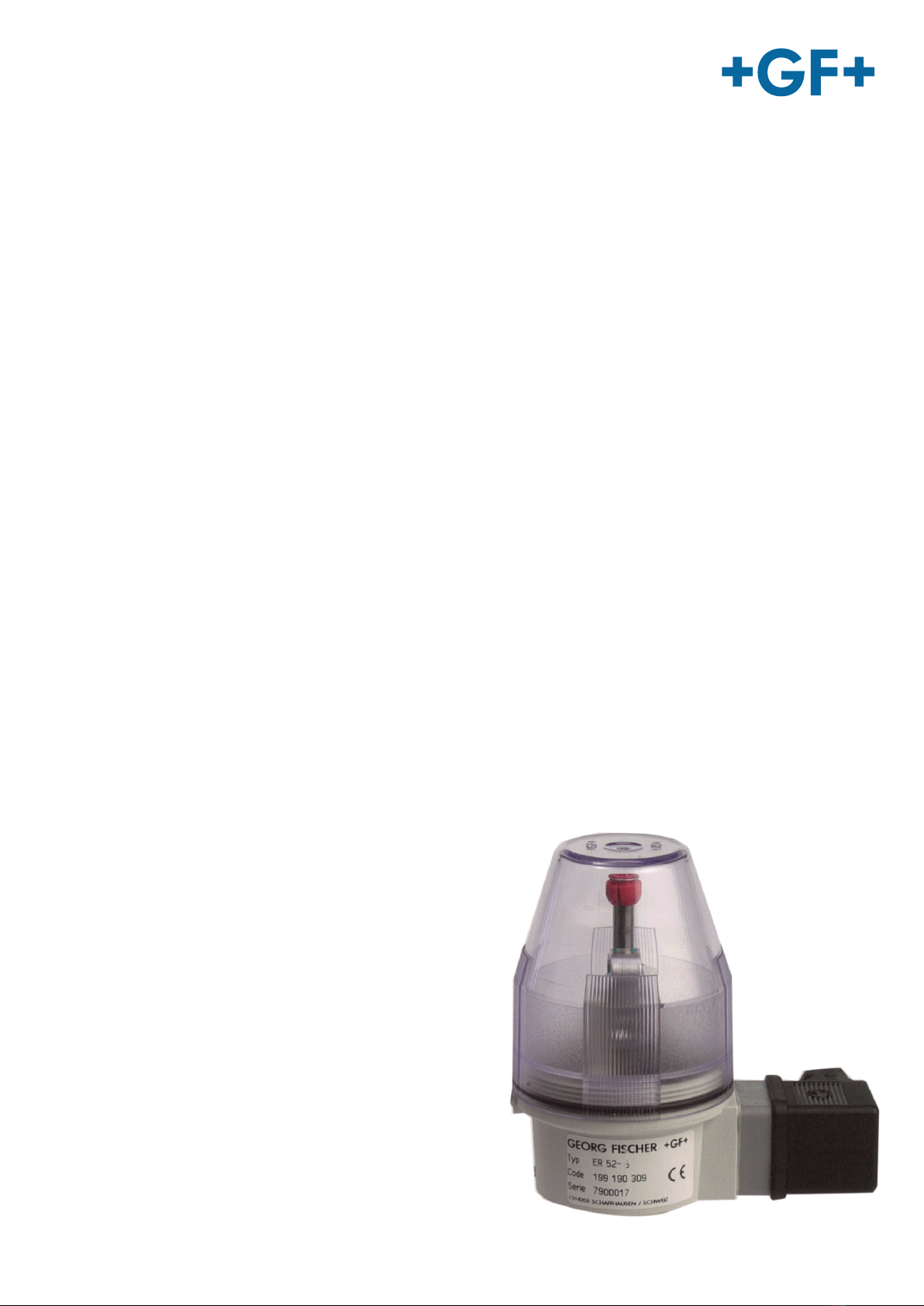
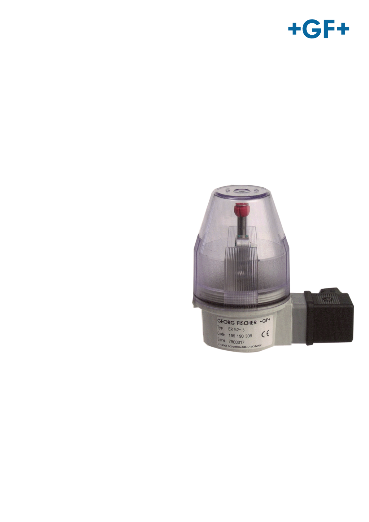
Electrical Position Indicator Type ER 52, ER 53
2.5 General safety information
NOTE!
These safety instructions do not take into account any contingencies and events that may occur during assembly, operation and
service of the devices, nor any location-related safety regulations, compliance with which, also with regard to the installation per-
sonnel, is the responsibility of the operator.
CAUTION!
Use only original parts!
Risk of material damage and/or injury due to non-compatible spare parts.
►Only use original spare parts from GF Piping Systems.
►Order spare parts using the information on the type plate.
►Do not use defective spare parts.
WARNING!
Do not use damaged products!
Danger of injury or material damage through the use of defective or damaged products.
►Do not use a damaged or defective product.
►Replace any damaged or defective products immediately.
CAUTION!
Leaking gaskets!
Danger of injury by leaking medium due to damaged or aged gaskets.
►Store gaskets if possible in a cool, dry and dark place.
►Before installing them, the gaskets have to be checked on possible aging damages, such as fissures and hardenings.
►Regularly check the gaskets and replace, where necessary.
2.6 Product-specific safety information
WARNING!
Risk of injury due to high pressure in the system/device.
►Before working on the system or device, switch o the pressure and vent/drain the lines.
Danger due to power supply!
►Before intervening in the device or the system, switch o the power supply and secure it against being switched on again.
►Observe the applicable accident prevention and safety regulations for electrical devices.
General dangerous situations. To protect against injury, note:
►That the system cannot be operated unintentionally.
►Only operate the device when it is in perfect condition and in compliance with the operating instructions.
►Installation and maintenance work may only be carried out by authorized specialist personnel using suitable tools.
NOTE!
Electrostatic sensitive components/assemblies!
The device contains electronic components that are sensitive to electrostatic discharge (ESD). Contact
with electrostatically charged persons or objects endangers these components. In the worst case,
they are immediately destroyed or fail after putting into operation.
►Take appropriate measures before touching the electronic components.
►Observe the requirements according to DIN EN 61340-5-1 to minimize or avoid the possibility of damage due to sudden electros-
tatic discharge!
►Do not touch electronic components when the operating voltage is present!