2 / 10
© Copyright: All rights reserved. Nothing from this publication may be reproduced, handed over,
co p ied, o r t ran s lated i n t o o t her l a ngua g es, in a ny fo rm o r mean s w ith o ut wr it ten p e rm i ssi on fr om Ply -
moVent A B. Plym oVent AB r e ser ves th e r ig ht to m a ke de s i gn - and tec h n ic a l c hang e s with o ut notic e.
PlymoVent AB, Industrigatan 26,
SE-212 14 Malmö, Sweden
Tel: +46 40 30 31 30, Fax +46 40 30 31 40
www.plymovent.se info@plymovent.se
Factory: PlymoVent AB
P.O. Box 527, SE-921 28 Lycksele, Sweden
Tel: +46 950 57 67 00, Fax +46 950 57 67 90
www.plymovent.se info@plymovent.se
BSAB no: U0.14
Ser.no: DCV
Date: Nov -07
Replace: June -03
TECHNICAL DESCRIPTION
DCV-Controller
DCV-Controller
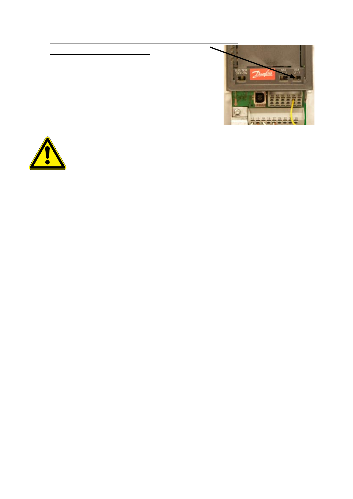
1.1 Frequency Inverter
Model VLT-HVAC
Enclosure IP55
Vibration test 0.7g RMS (IEC-68-2-34/35/36)
Ambient temperature max.50°C
min. 0°C (full operation)
min. -10°C (reduced operation)
Temp. storage/transport -25 °C to 65 °C
Max. altitude above sea 1000 m
Max. relative humidity 93% +2% -3% (storage/transport)
95% non-condensing (operation)
For additional details – consult the inverter handbook.
1.2 Pressure Transmitter
Measuring range 0-1600 Pa (TG-1600)
0-2500 Pa (TG-2500)
0-5000 Pa (TG-5000)
Enclosure IP54
Output signal 4-20 mA
Supply voltage 18 .. 33 VDC
Power Consumption 30 mA
Membrane material LSR (silicon)
Pressure connection 6 mm
Cable connection screw terminals
Linearity < +/- 0.7% fs
Hysteresis < +/- 1% fs
Ambient temperature 0 – 70 °C
Storage temperature -10 – 70 °C
TO ACHIEVE OPTIMUM PERFORMANCE AND
SAFETY, PLEASE READ THE MANUAL CARE-
FULLY!
1 Technical data
Address Tel Fax e-mail
PlymoVent Ltd Marley Way, Southam Rd, 01295 25 93 11 01295 25 17 50 info@plymovent.co.uk
www.plymovent.co.uk Banbury OX16 2RA, England
PlymoVent GmbH Heideweg 24, 02224 97300 02224 89646 info@plymovent.de
www.plymovent.de D-53604 Bad Honnef Germany
PlymoVent SA B.P. 30, Zone Industrielle de Mavault 549 51 55 88 549 51 59 33 info@plymovent.fr
www.plymovent.fr F-86170 Neuville de Poitou, France
PlymoVent Corp. 115 Melrich Road 732 417 0808 732 417 1818 info@plymoventusa.
www.plymovent.com Cranbury, New Jersey 08512, USA
PlymoVent Inc. 24 - 1200 Aerowood Dr. 905 564 4748 905 564 4609 info@plymovent.ca
www.plymovent.ca Mississauga, ON L4W 2S7, Canada