PUM_VSR_100209_EN 3/200
4. SAFETY
General
The manufacturer does not accept any liability for damage to
the product or personal injury caused by ignoring of the safety
instructions in this manual, or by negligence during installation,
use, maintenance, and repair of the product mentioned on the
cover of this document and any corresponding accessories.
Specic working conditions or used accessories may require
additional safety instructions. Immediately contact your supplier
if you detect a potential danger when using the product.The
user of the product is always fully responsible for
observing the local safety instructions and regulations.
Please observe all applicable safety instructions and regulations.
User manual
• Everyoneworkingonorwiththeproduct,mustbefamiliar
with the contents of this manual and must strictly observe
the instructions herein.The management should instruct
the personnel in accordance with the manual and observe
all instructions and directions given.
• Neverchangetheorderofthestepstoperform.
• Alwayskeepthemanualwithorneartheproduct.
Pictograms and instructions on the product (if present)
• Thepictograms,warningandinstructionsattachedtothe
product are part of the safety features. They must not be
covered or removed and must be present and legible during
the entire life of the product.
• Immediatelyreplaceorrepairdamagedorillegible
pictograms, warnings and instructions.
Users
• Theuseofthisproductisexclusivelyreservedtoauthorized,
trained and qualied users.Temporary personnel
and personnel in training can only use the product under
supervision.
Intended use
The product has been designed as an exhaust removal system.
Using the product for other purposes is considered contrary
to its intended use. The manufacturer accepts no liability for
any damages or injury resulting from such use. The product has
been built in accordance with state-of-the-art standards and
recognized safety regulations. Only use this product when in
technical perfect condition in accordance with its intended use
and the instructions explained in the user manual.
Technical specications
The specications given in this manual must not be altered.
Modications
Modications of (parts of) the system / product is not allowed.
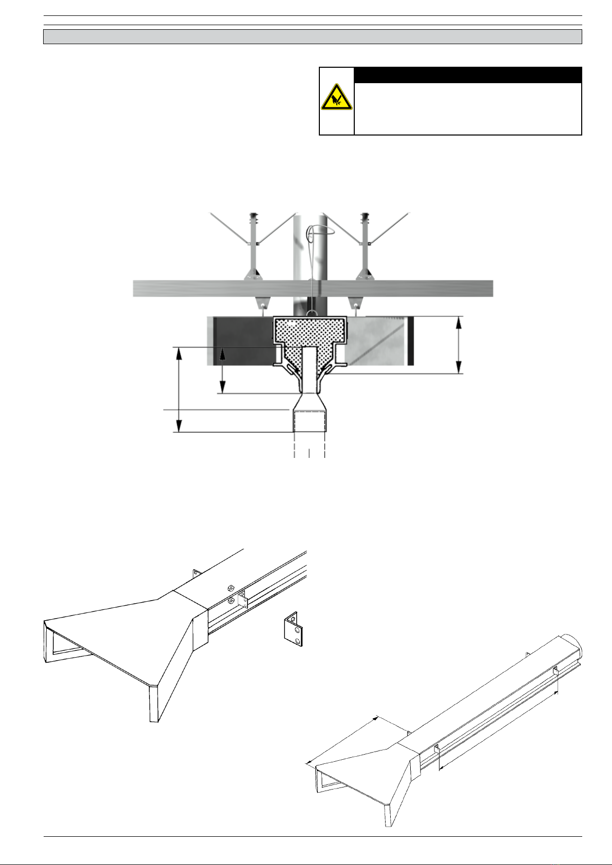
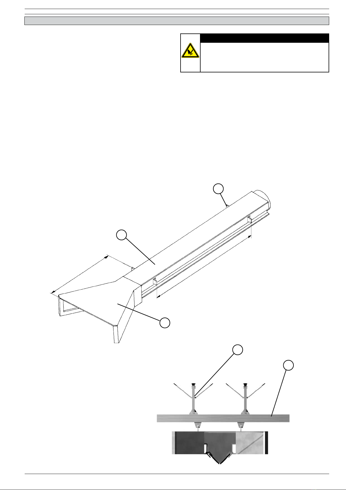
WARNING
PRODUCT MAY CONTAIN SHARP EDGES
Use care when servicing and installing the system.
Failure to do so could result in minor personal
injury.
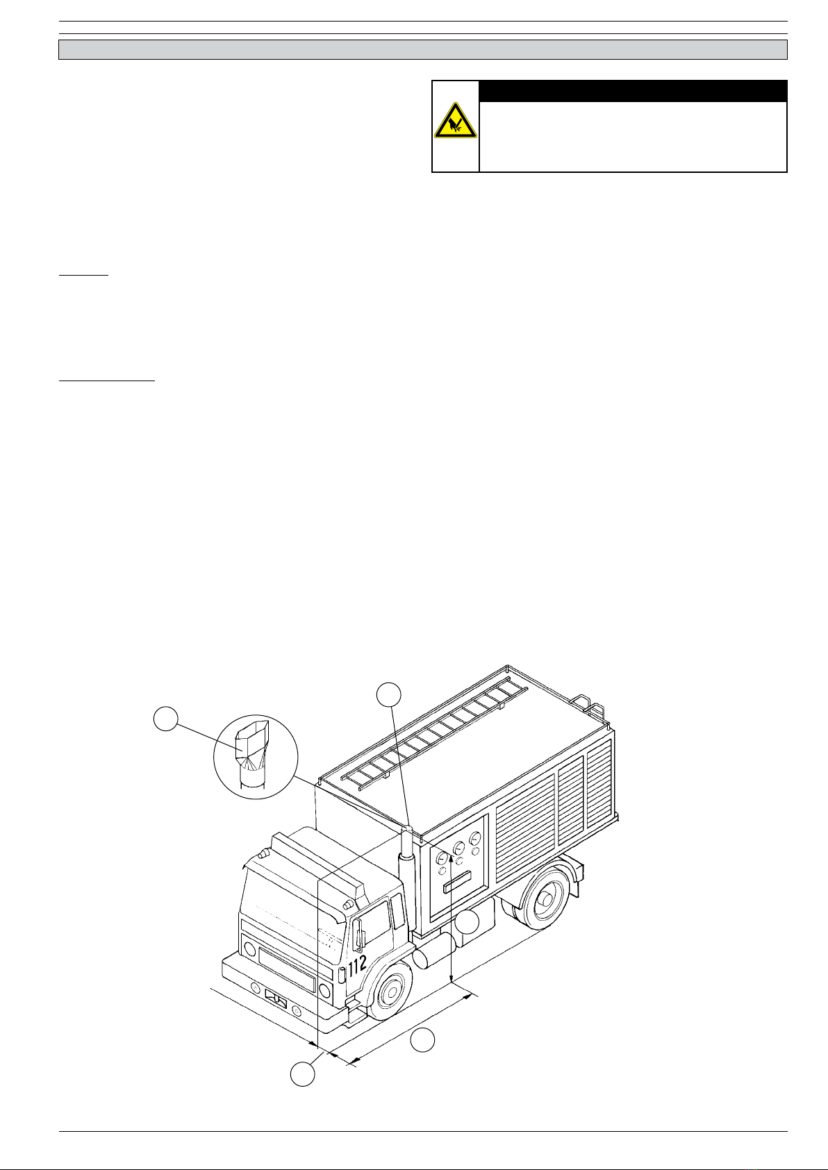
WARNING
Do not attempt installation of this system unless
you are familiar with the necessary tools, equipment,
utility connections and potential hazards. Installation
should be performed only by a qualied service
provider. Failure to do so could result in reduced
performance of the unit, serious personal injury or
death.
General information and installation
• Inspecttheproductandcheckfordamages.Verifythe
functioning of the safety features.
• Checktheworkingenvironment.Donotallowunauthori-
zed persons to enter the working environment.
• Protecttheproductagainstwaterandhumidity.
• Usecommonsense.Stayalertandkeepyourattentionto
your work. Do not use the product when you are under the
inuence of drugs, alcohol or medicine.
• Makesuretheroomisalwayssufcientlyventilated;this
applies especially to conned spaces.
• makesuretheproductdoesnotblockanyentrancesand
exits which must be used for emergency services.
• Makesurethattheworkshop,inthevicinityoftheproduct,
contains sufcient approved re extinguishers if any
elctronics, such as control boxes, are used.
Service, maintenance and repairs
• Observethemaintenanceintervalsgiveninthismanual.
Overdue maintenance can lead to high costs for repair and
revisions and can render the guarantee null and void.
• Alwaysusetools,materials,lubricantsandservicetechni-
ques which have been approved by the manufacturer.
Never use worn tools and do not leave any tools in or on
the product.
• Safetyfeatureswhichhavebeenremovedforservice,
maintenance or repairs, must be put back immediately after
nishing these jobs and it must be checked that they still
function properly.
ATTENTION!
Maintenance should only be performed by autho-
rized, qualied and trained persons (skilled) using
appropriate work practices.