9
567
LIMITED WARRANTY
SHORT SUMMARY OF LIMITED WARRANTY FOR WAYFINDER®V2020
For the Full Warranty and Limitation of Liability applicable to this
product, see our Website at www.pnicorp.com, select “Consumer
Products” and click “Download”.
PNI Corporation ("PNI") manufactures its products from parts and
components that are new or equivalent to new in performance, and
warrants to the original user that this product will be free of defects in
workmanship and materials for one (1) year from the date of purchase.
is warranty does not cover wear and tear due to normal use, or damage
to the product as the result of improper usage, neglect of care, alteration,
accident or unauthorized repair.
If the product is found by PNI to be defective, PNI will repair or replace
the product and return the product or its replacement to you at no charge,
provided that you ship the product to PNI at your expense with a
description of the defect and subject to the other conditions of this
warranty. Should the product prove to be irreparable, PNI may substitute
an equivalent product of the same or similar style and of a value not in
excess of the original purchase price of your unit.
PNI warrants the repaired or replacement product to be free from defects
in material and workmanship on the same terms as the product originally
purchased.
is warranty will be void if the products, serial number or other
identification marks have been defaced, damaged or removed. is
warranty does not apply to the battery necessary to operate the product.
is warranty is extended to the original retail purchaser only and may not
be transferred or assigned to subsequent owners. In order to validate your
warranty, you must provide proof of purchase acceptable to PNI together
with the product shipped for warranty repair/replacement.
Products returned to PNI must be pre-authorized by PNI with an RMA
(return material authorization) number marked on the outside of the
package. Please refer to the Service and Replacement section for PNI
Corporation contact information.
www.pnicorp.com
FCC COMPLIANCE
is device complies with Part 15 of the FCC Rules. Operation is subject
to the following two conditions:
(1) this device may not cause harmful interference, and
(2) this device must accept any interference received, including interfer-
ence that may cause undesired operation.
Warning: Changes or modifications to this unit not expressly approved by
the party responsible for compliance could void the user’s authority to
operate the equipment.
Note: is equipment has been tested and found to comply with the
limits for a Class B digital device, pursuant to part 15 of the FCC Rules.
ese limits are designed to provide reasonable protection against harmful
interference in a residential installation. is equipment generates, uses
and can radiate radio frequency energy and, if not installed and used in
accordance with the instructions, may cause harmful interference to radio
communications. However, there is no guarantee that interference will not
occur in a particular installation. If this equipment does cause harmful
interference to radio or television reception, which can be determined by
turning the equipment off and on, the user is encouraged to try to correct
the interference by one or more of the following measures:
• Reorient or relocate the receiving antenna.
• Increase the separation between the equipment and receiver.
• Connect the equipment into an outlet on a circuit different
from that to which the receiver is connected.
• Consult the dealer or an experienced radio/TV technician
for help.
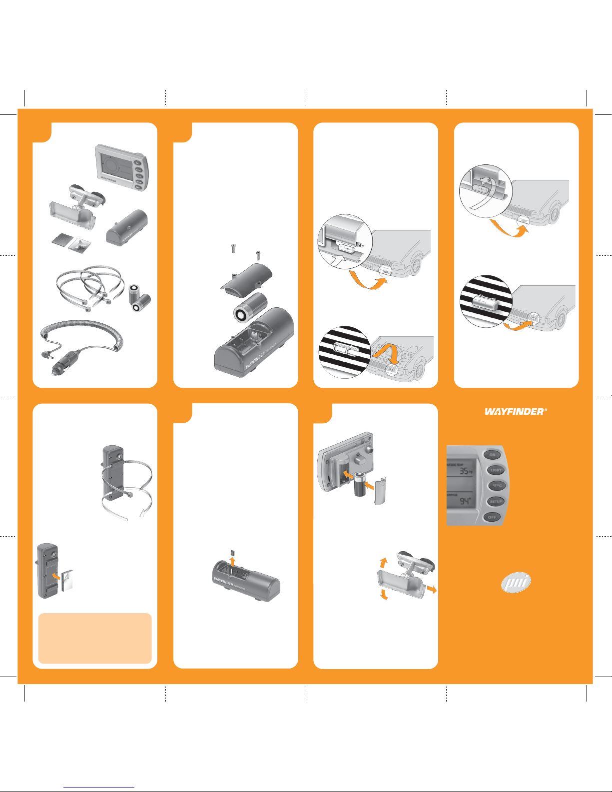
SETTING UP
THE COMPASS
e compass must be setup in order to provide accurate readings.
Always setup the compass AFTER the Wayfinder Display Unit
has been mounted on your windshield.
1) Drive to an area where you can easily turn your
vehicle in a small circle (such as an empty parking lot or
cul-de-sac).
2) Press the SETUP button.e screen will read
“PRESS SETUP FOR 2 SECS”.
3) Press and hold the SETUP button for 2 seconds.
e screen will begin displaying “TURN CAR IN
FULL CIRCLE.”
4) Drive your vehicle in one complete circle (any
direction). Once you’ve begun the maneuver, the screen
will display “PRESS SETUP WHEN DONE”.
5) When you’ve completed the circle, press SETUP.
e screen will display “SETUP DONE”.
6) Changing your bracket angle, the mounting location
or the battery will require you to setup the compass
again.
NOTE: For maximum accuracy, all compasses should be reset
every 3 months due to ongoing changes in magnetic fields.
C. Backlight
1) When battery operated:
a. Press the LIGHT button to turn the backlight on
for 30 seconds.
b. Press and HOLD the LIGHT button for 2 seconds
to keep the backlight on continuously.
i. In daylight conditions, the backlight will
automatically turn off after 2 minutes.
c. Press the LIGHT button again to turn off the
backlight.
2) When 12-volt operated:
If your unit is plugged into a 12V socket, the backlight
will automatically turn on in low-light conditions,
and turn off in daylight conditions.
D. Signal Strength
You may occasionally want to check your Sensor’s signal to be sure
you’re getting accurate readings.
1) Press and HOLD the oF/oC button for 2 seconds.
2) A number from 1 to 10 will appear in the Outside
Temp field.
3) A signal reading of “5”or above indicates your sensor
is working well.
4) Any number below “5”indicates your signal strength
is weak and you should adjust the location of your
sensor.
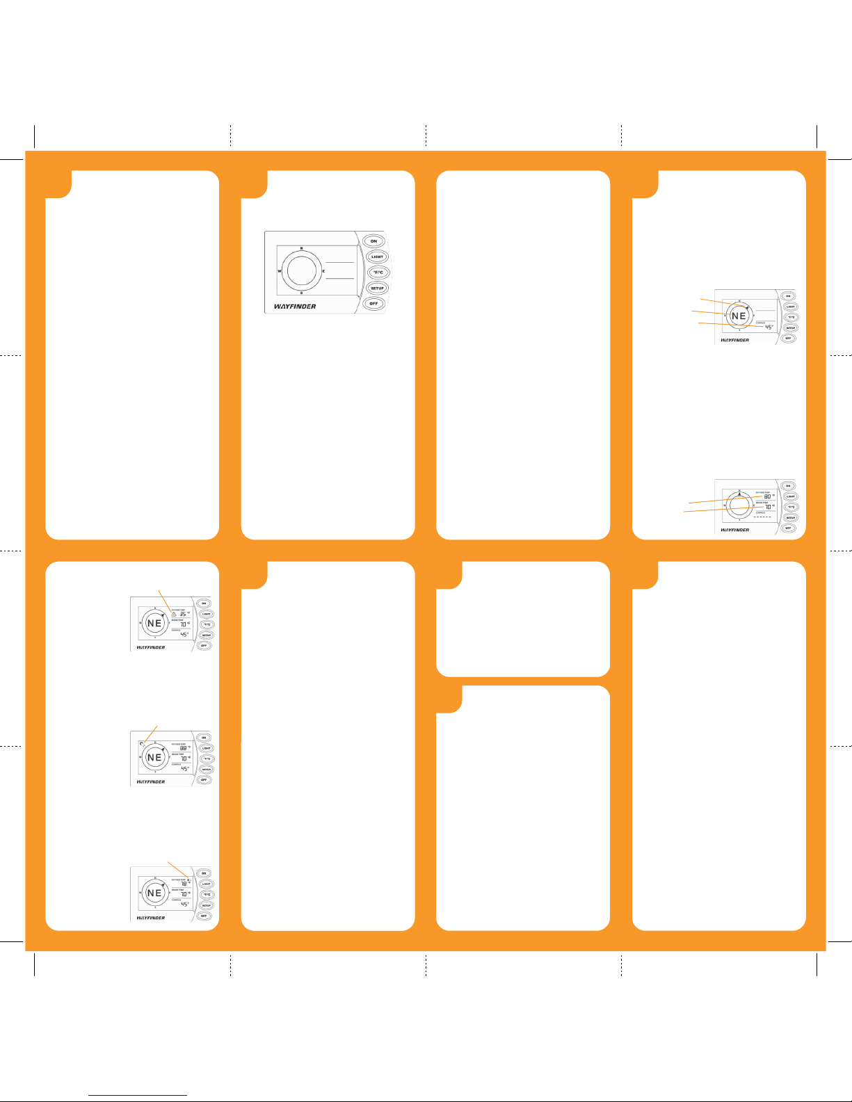
READING THE DISPLAY
A. Compass Directions
1) e compass rose provides an alpha readout of the
direction your vehicle is headed (N, NW, etc.)
2) An arrow revolves around the compass rose to the
appropriate directional heading as the vehicle changes
direction.
3) e Compass section of the screen provides a digital
numeric readout of your compass heading.
B. Temperature Signals
1) When first turned on, the OUTSIDE TEMP field
displays “---” for several minutes while the unit
acquires a signal from the Temp Sensor.
NOTE: e INSIDE TEMP field will not appear
on the display until you have installed an inside Temp
Sensor and a signal is detected. is can take several
minutes.
2) Temperature readings can be switched from oF to oC
(press the
oF/oC button to toggle).
NOTE: Temperature readings may be inaccurate
while the vehicle is parked, and for several minutes
after startup until airflow to the Sensor is established.
TROUBLESHOOTING
A. e temperature reading on the
display appears to be incorrect.
1) Check the Outside Temp Sensor’s signal strength,
following the instructions in section #6.
2) Adjust the Sensor location if needed. Try to ensure the
Sensor is:
ÿ
At least 3 to 4 inches away from the radiator so
that it doesn’t pick up residual engine heat
ÿ
Sitting away from direct sunlight (for instance, on
the inside of your vehicle bumper, rather than the
outside)
ÿ
Located in an area that allows airflow around the
sensor
3) Check the location of the Inside Temp Sensor, being
sure it is situated away from direct sunlight.
4) Remember that the temperature readings will be inac-
curate while the vehicle is parked, and for several
minutes after vehicle start-up until airflow to the
Sensor is established.
B. e compass reading on the display
appears to be inaccurate.
1) Be sure you’ve setup the compass using the instructions
in section #5.
2) Check to see that the batteries are still active, and
then setup the compass again.
3) Look to see whether the magnet icon is flashing in
the upper left corner. is indicates the compass has
encountered interference, and you will need to setup
the compass again.
4) If you’ve just moved the Wayfinder to a new location,
setup the compass again.
SERVICE
AND REPLACEMENT
If you wish to return your Wayfinder directly to PNI Corporation,
contact us between 8:00 a.m. and 5:00 p.m. (PST) Monday
through Friday at the following phone numbers or email address.
We’ll give you instructions for returning your Wayfinder for repair
or replacement.
Phone: (707) 566-2260
Fax: (707) 566-2261
USING THE BUTTONS
A. Button Functions
ON – turns the Display Unit on
LIGHT – turns the backlight on and off
oF/oC– switches between Fahrenheit
and Celsius readings
SETUP – begins compass setup
OFF – turns the Display Unit off
B. Automatic On and Off
1) When plugged into the 12V adapter, the Wayfinder
display unit will automatically turn on when your
vehicle engine is started.
2) e Wayfinder display unit will shut off automatically
after 10 minutes with no detectable change in vehicle
direction.
8
10
11
C. Ice Alert Warning
When the outside tem-
perature reaches 35oor
lower, an ice alert warning
icon appears next to the
OUTSIDE TEMP
reading.
D. Magnetic Distortion Warning
1) When the compass is temporarily unable to provide
accurate readings due to a disturbance in the magnetic
field (for instance, when you’re crossing railroad tracks),
a magnet icon will flash in the upper left corner of the
screen.
2) Once your vehicle
has moved away from
the source of interfe-
rence, the magnet
icon will disappear.
3) If the magnet icon
continues flashing,
setup the compass
again.
E. Battery Low Warning
When your Display Unit or Temp Sensor battery is low, a Battery
Low icon will appear on the display as follows:
1) In the OUTSIDE TEMP section when the outside
temp sensor battery is low;
2) In the INSIDE
TEMP section when
the inside temp sensor
battery is low;
3) In the COMPASS
section when the
Wayfinder display
unit battery is low.
Directional Arrow
Alpha Readout
Numeric Readout
Outside Temp
Inside Temp
Ice Alert Icon
Magnet Icon
Battery Low Icon