Poindus VariPOS 815 User manual

© Copyright Poindus Systems 2012 P1 / 54
User Manual
Version V2.1 Dec. 2012
VariPOS™815

© Copyright Poindus Systems 2012 P2 / 54
Contents
Contents------------------------------------------------------------------2
Notices----------------------------------------------------------------------------------------------------3
Safety information---------------------------------------------------------------------------------------4
CE verification--------------------------------------------------------------------------------------------5
FCC verification------------------------------------------------------------------------------------------6
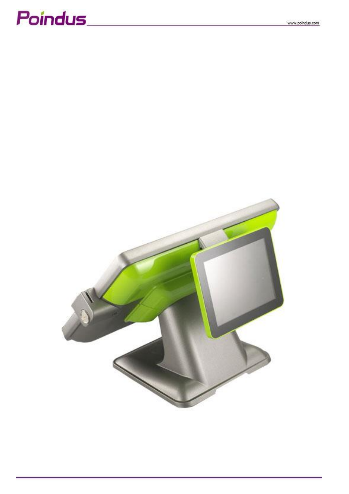
Welcome-----------------------------------------------------------------7
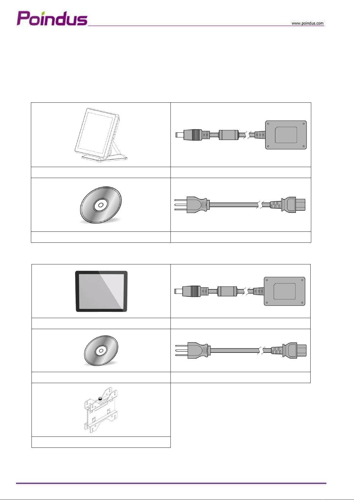
Package contents----------------------------------------------------------------------------------------7
Accessory items------------------------------------------------------------------------------------------8
Getting to know your VariPOS/VariPPC-------------------------------9
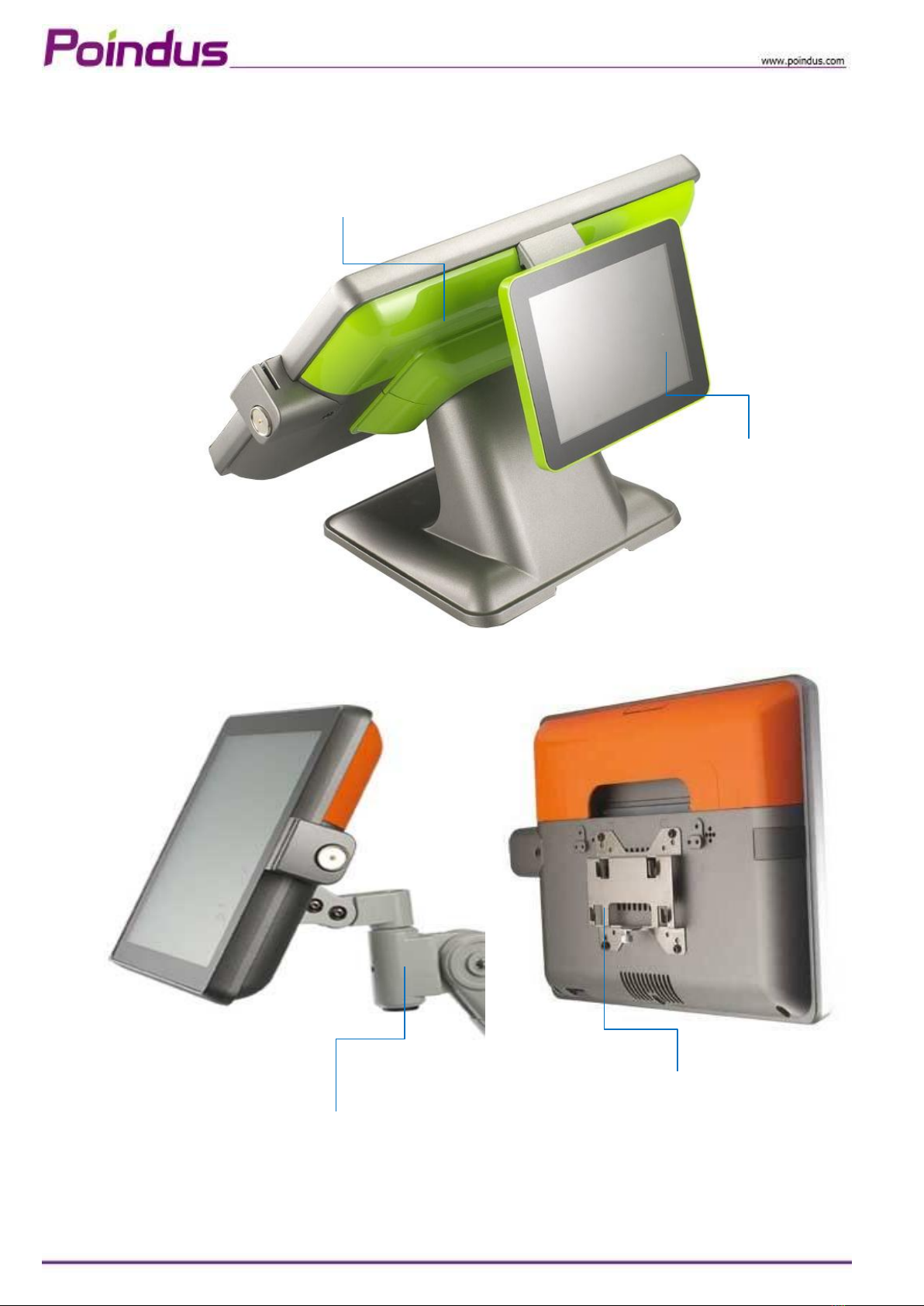
Front view------------------------------------------------------------------------------------------------9
Rear view------------------------------------------------------------------------------------------------10
Optional I/O interface---------------------------------------------------------------------------------11
Using the touch screen--------------------------------------------------------------------------------12
Specification------------------------------------------------------------15
System Assembly & Disassembly------------------------------------17
Open the system----------------------------------------------------------------------------------------17
Replace the HDD----------------------------------------------------------------------------------------19
Install the Customer display---------------------------------------------------------------------------21
Configure the Com3 Pin9 for customer display-----------------------------------------------------22
Install the second display------------------------------------------------------------------------------24
How to configure the 2nd display resolution---------------------------------------------------------27
Install the external monitor---------------------------------------------------------------------------29
Install the cash drawer---------------------------------------------------------------------------------30
Install the MSR & I-Button Reader--------------------------------------------------------------------32
Install the Die-casting aluminum base---------------------------------------------------------------33
Install the Wall Mount kits-----------------------------------------------------------------------------34
Motherboard information---------------------------------------------35
Motherboard Layout------------------------------------------------------------------------------------35
Connectors & Jumper Settings------------------------------------------------------------------------36
Spare parts list---------------------------------------------------------38
Version Change History-----------------------------------------------54

© Copyright Poindus Systems 2012 P3 / 54
Notices
The information contained in this document is subject to change without notice.
We make no warranty of any kind with regard to this material, including, but not limited to, the implied warranties of
merchantability and fitness for a particular purpose. We shall not be liable for errors contained herein or for incidental or
consequential damages in connection with the furnishing, performance, or use of this material.
Proprietary information contained in this document is copyright protected. Photocopying, producing or translating this
document or any part of it without obtaining a written consent from Poindus is prohibited. Changes in this document or
in the products described herein may be made without prior notice. Incidental or consequential damage/s related to the
use of this document is not Poindus liability.
Including but not limited to the implied warranties of merchantability or fitness for a particular purpose, POINDUS make
this publication available without warranty of any kind.
TRADEMARK
Poindus®/ VariPOS TM are registered trademarks of Poindus Systems.
Intel®/ Core i3/i5 are registered trademarks of Intel ® Corporation. Microsoft®and Windows®are registered trademarks
of Microsoft Corporation.
Other trademarks mentioned herein are the property of their respective owners.

© Copyright Poindus Systems 2012 P4 / 54
Safety information
IMPORTANT SAFETY INSTRUCTIONS
1) Carefully read and follow these instructions. Pay attention to the danger and caution labels displayed on the
product.
2) Only operate the product based on the type of power indicated on the label. Consult your dealer or local power
company if unsure of the type of power available.
3) Make sure the power cord is placed safely where it would not be walked on. Do not rest anything on the power
cord.
4) In disconnecting the machine from the electrical power supply, first switch off the power button, and then remove
the power plug from the wall socket.
5) This product must not be placed on an unstable platform such as a stand or table for its fall may cause serious
damage to the product.
6) Slots and openings are there to provide proper ventilation, prevent overheating and ensure reliable operation of
the product, thus must not be blocked or covered. Do not place the product on a bed, sofa, rug or the like so as to
avoid blocking the openings. Unless proper ventilation is provided, never place the product over or near a radiator,
heat register or a built-in installation.
7) Never insert any kind of objects through the openings/slots to avoid touching dangerous voltage points which
could cause electric shock or fire.
8) If there is smoke or strange smell, unplug the power cord from the power outlet immediately and request repair
from your dealer or POINDUS.
CE
This device complies with the requirements of the VariPOSTM directive 2004/108/EC with regard to
“Electromagnetic compatibility”.
FCC
This device complies with part 15 of the FCC rules. Operation is subject to the following two
conditions:
(1) This device may not cause harmful interference.
(2) This device must accept any interference received, including interference that may cause
undesired operation

© Copyright Poindus Systems 2012 P5 / 54

© Copyright Poindus Systems 2012 P6 / 54

© Copyright Poindus Systems 2012 P7 / 54
Welcome
Congratulations on your purchase of VariPOS/VariPPC. The following illustration displays the package contents of
your new product. If any of the following items is damaged or missing, please contact Poindus.
Package contents
【VariPOS 815™】
VariPOS
Power adapter
Driver bank CD
Power cord
【VariPPC 815TM 】
VariPPC
Power adapter
Driver bank CD
Power cord
Wall mount kit

© Copyright Poindus Systems 2012 P8 / 54
Accessory items
Part No
Description
Q’ty
1
3XCC00000010
Touch Screen Wipes ,20*15mm
1
2
3XPP00000010
SPIRAL WARPPING BANDS SWB-16,L15mm
1
3
*7P0000000030
*1SCREW PACK: security screws
1
Screw driver
1
4
3CMD9MJT0100
RJ-45 Cable
2
5
3CW000000190
VGA Cable*2
1
6
3CW000000550
PS/2 CABLE
1
*1: There are security screws and a screw driver for replacing the hard drive fixing screw. Customers can
use the security screws to ensure HDD security.
*2: VGA Cable is only for I/O interface with VGA port.

© Copyright Poindus Systems 2012 P9 / 54
Getting to know your VariPOS/VariPPC
Front view
*all peripherals are depends on customer’s demand
Customer display*
(VFD)
True flat touch panel
Resistive/PCT
Power LED
Peripheral
*(RFID/I-Button/MSR/FP)
Die-casting aluminum base

© Copyright Poindus Systems 2012 P10 / 54
Rear view
*all peripherals are depends on customer’s demand
Diverse colors I/O cover
7”2nd display*
ARM kit for VariPPC only*
Wall mount kit for VariPPC only

© Copyright Poindus Systems 2012 P11 / 54
Optional I/O interface
【Standard Version】
The last I/O is LPT port
【VGA Version】
The last I/O is VGA port

© Copyright Poindus Systems 2012 P12 / 54
Using the touch screen
Touch Driver Installation:
The shipping package includes a Driver CD. You can find every individual driver and utility that enables you to
install the drivers in the Driver CD.
Please insert the Driver CD into the drive and double click on the “autorun.exe” to pick up the models.
Notice:
1. If you use the Resistive touch panel, it is only showed COM6 after the installation.
2. If you use the PCT touch panel, it will show the below image, please remove COM6 icon.
3. At the Windows 7 Operation System environment, when customer want to use PCT touch multi-touch it is not
required to install the touch driver.
4. Resistive touch is RS232 interface (COM6) and the PCT touch is USB interface.

© Copyright Poindus Systems 2012 P13 / 54
5. Calibration with EETI touch utility: please into “tool” page and press “4 Points Calibration”.
6. Calibration in WIN7: Control panelHardware and SoundTablet PC settingCalibrate the screen from pen or
touch input

© Copyright Poindus Systems 2012 P14 / 54
With a finger to touch, you can make VariPOS/VariPPC work at your command.
Your touch functions like a mouse device:
• Touch = left-click on the mouse
• Touch and hold = right-click on the mouse
Cleaning the touch screen
The touch screen requires periodic cleaning to achieve the best touch sensitivity. Keep the screen clean from foreign
objects or excessive dust accumulation.
To clean the screen:
• Turn off the system and disconnect the power cord from the wall.
• Spray a small amount of a household glass cleaner onto the supplied cleaning cloth and gently wipe the screen
surface.
• Do not spray the cleaner directly on the screen. (Resistive touch panel only)
• Do not use an abrasive cleaner or a coarse cloth when cleaning the screen.

© Copyright Poindus Systems 2012 P15 / 54
Specification
Motherboard
CPU
Intel® Mobile Celeron B810 1.6GHz with L3 Cache 2MB
Intel® i3-2330E 2.2 GHz with L3 Cache 3MB
Intel® i5-2510E 2.5 GHz with L3 Cache 3MB
Chipset
HM65
System Memory
1 x SO-DIMM DDRIII 1333, up to 8GB
Display
TFT LCD
38.1cm (15”)
Brightness
250nits
Resolution
1024 x 768
Touch Screen
True Flat Projected Capacitive Technology / True Flat 5-Wire Resistive
Storage
HDD / SSD Type
1 x SATA 6.4cm (2.5”)HDD , SSD (optional)
Compact Flash Type
N/A
I/O Ports -External
DC Input
1 x Mini Din 4P (DC 12V only)
Cash Drawer
1 x RJ-11 (Power Pin 12V)
Network (LAN)
1 x Gigabit Ethernet by RJ-45
USB Port
4 x USB 2.0
Serial Port
4 x RS-232
COM1/2 : DB-9, RS-232, Pin9 w/RI/5V/12V Selectable by BIOS
COM3/4 : RJ-48 , RS-232, Pin10 w/RI/5V/12V Selectable by BIOS
Audio Port
1 x Line-out ; 1 x Mic-In
PS/2 Port
1 x PS/2 connector for Keyboard
LPT Port
1 x DB-25 Printer Port (Standard)
VGA Port
1 x DB-15 VGA Port (Optional)

© Copyright Poindus Systems 2012 P16 / 54
I/O Ports -Internal
Card Reader & I-Button
COM5 : Internal Pin header for Card Reader & I-Button
Audio
HD Audio, 2W Speaker x 2
Bus Expansion
1 x Mini-PCI-E Slot
Compliance
IP 66 on front panel
System Management
Desktop Management Interface (DMI)
Preboot Execution Environment (PXE)
Wake on LAN (WoL)
Advanced Configuration and Power Interface (ACPI)
OS Support
Windows 7 Professional for Embedded Systems, Windows Embedded Standard 7,
Windows Embedded POSReady 7, Ubuntu 12
Power Supply
External adapter, DC Model:120 Watts, Voltage:+12VDC 10 Amax
Material
Main Unit: Die-casting aluminum ; I/O Cover: Plastic
Color
Main Unit: Grey / White / Black *Customized color for plastic parts
Certifications
CE, FCC, Class-B, RoHS, WEEE
Dimension( W x H x D )
370 x 300 x 236 mm
Weight
5.96 Kg (Aluminum Base: 1 Kg )
VESA Mounting
100 x 100mm
Operating Temperature
0ºC ~ 40ºC, 10% ~ 90% RH, non-condensing
Storage Temperature
-20ºC ~ 60ºC, 10% ~ 90% RH, non-condensing
*Poindus reserves the right to change the specification without prior notice.

© Copyright Poindus Systems 2012 P17 / 54
System Assembly & Disassembly
Open the System
To access the inside system, you need to open the system first and the procedure of opening the system is as below:
1. Open the back IO cover
2. Release the screws of VFD
3. Release the screws of hinge cover
4. Remove the plastic hinge cover parts
5. Release the screws of base
6. Open the plastic cover from two sides
7. Release the screws of aluminium back frame

© Copyright Poindus Systems 2012 P18 / 54

© Copyright Poindus Systems 2012 P19 / 54
Replace the HDD
1. Open the IO back cover
2. Release the 1x screw from HDD tray
3. Remove the HDD tray.
4. Release the 4 x round screws on the HDD tray and replace HDD
5. Screw 4 x round screws on the HDD tray and insert the HDD tray into the whole system HDD slot
6. Fix HDD tray on the system with the 1x screw

© Copyright Poindus Systems 2012 P20 / 54
Screw Pack
Item
Part No.
Description
Q’ty
A
3SMFH30040N0
F-HEAD SCREW:M3*0.5-4mm,NI
5
B
3SMPH30062N0
P-HEAD SCREW:M3*0.5-6mm,NI(FLOWER)
2
C
3SLFR03651B0
Screwdriver(FLOWER)
1
D
3SMUH30061N0
ROUND WASHER HEAD SCREWS:m3*0.5-6MM,NI
3
* There are security screws and a screw driver enclosed in product carton.
* Customers can use the special security screws to ensure HDD security.
Security Screws*
This manual suits for next models
1
Table of contents
Other Poindus Touch Terminal manuals
Popular Touch Terminal manuals by other brands

Rockwell Automation
Rockwell Automation Allen-Bradley PanelView 800 user manual

Zircon
Zircon POP-950-D5 user manual

XAC
XAC xCE_E200I-15YXF installation guide

Mitsubishi
Mitsubishi GOT1000 Series Connection manual

Advanced Kiosks
Advanced Kiosks Free Standing Kiosk owner's manual

Unitech
Unitech TASHI MT180 Quick reference guide