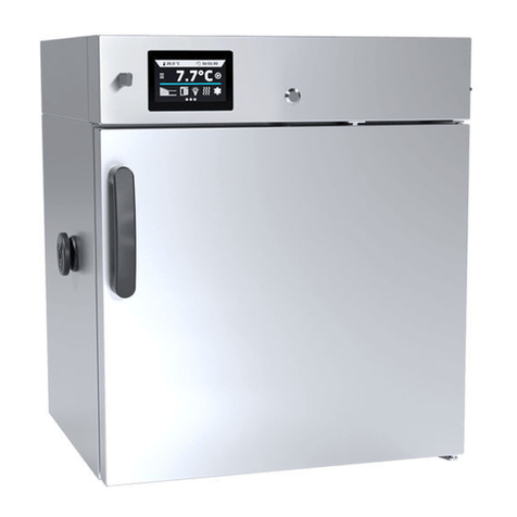
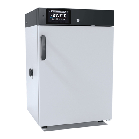
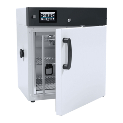
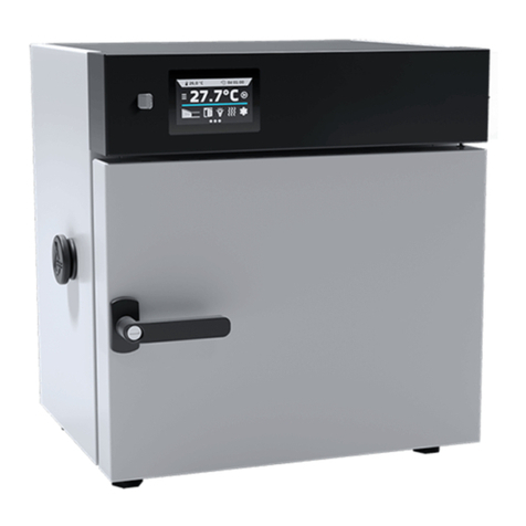
POL-EKO SMART PRO KKS 115 User manual

1
Climatic chambers
with ultrasonic humidifier
models: KK 115, KK 240, KK 350, KK 400, KK 500, KK 700,
KK 750, KK 1200, KK 1450
Climatic chambers
with steam humidifier
models: KKS 115, KKS 240, KKS 400, KKS 750
Before using the equipment, please read carefully this instruction manual!
Version 1.29
Issued 12.05.2022
Instruction manual SMART PRO

Instruction manual KK, KKS SMART PRO
2
Manufacturer's address:
POL-EKO-APARATURA sp. j.
ul. Kokoszycka 172 C
44-300 Wodzisław Śląski
Country of origin: Polska
As a manufacturer, we inform you that we took the necessary measures to ensure that this device fully meets your
expectations and is reliable for a long period of use. Due to the continuous improvement of our products, as well as the
expansion of our offer, any suggestions regarding additional functions and equipment functioning are welcome. Visit
our homepage www.pol-eko.com.pl/home-en/
Equipment disposal
This equipment is marked with the crossed out wheeled bin symbol to indicate that this equipment must not be dis-
posed of with unsorted waste. Instead it's your responsibility to correctly dispose of your equipment at lifecycle -end by
handling it over to an authorized facility for separate collection and recycling. It's also your responsibility to
decontaminate the equipment in case of biological, chemical and/or radiological contamination, so as to protect from
health hazards the persons involved in the disposal and recycling of the equipment. For more information about where
you can drop off your waste of equipment, please contact your local dealer from whom you originally purchased this
equipment.
By doing so, you will help to conserve natural and environmental resources and you will ensure that your equipment is
recycled in a manner that protects human health.
Thank you!

Instruction manual KK, KKS SMART PRO
3
Contents:
1. INTENDED USE AND IMPORTANT INFORMATION FOR THE USER.........................................................6
2. PACKAGE CONTENTS..................................................................................................................................7
3. BEFORE THE FIRST USE..............................................................................................................................8
3.1. Reverse osmosis system (standard for KKS) .......................................................................................10
3.1.1. Working conditions and requirements ..............................................................................................10
3.1.2. Delivery range..................................................................................................................................11
3.1.3. Preparing the system to work...........................................................................................................11
3.1.4. Connecting the system to the KKS chamber....................................................................................13
3.1.5. Consumables and service life of reverse osmosis system ..............................................................16
3.1.6. Filters replacement FCPS20, FCCBL and FCPS5 ...........................................................................16
3.1.7. Osmotic membrane replacement .....................................................................................................17
3.1.8. Linear cartridge replacement............................................................................................................18
3.1.9. Tank replacement.............................................................................................................................20
3.2. Installation of a water tank in the KK climatic chamber.........................................................................21
3.3. Installation of the condensate tray in KK climatic chamber...................................................................22
3.4. Installation of shelves ...........................................................................................................................25
3.5. Internal glass door (standard for KK and KKS).....................................................................................26
3.6. Condensation in the chamber...............................................................................................................26
3.7. Remarks on the placement of samples.................................................................................................27
3.8. Closing chamber door...........................................................................................................................27
4. DESCRIPTION OF THE DEVICE..................................................................................................................27
4.1. Design of KK / KKS devices .................................................................................................................28
5. DEVICE EQUIPMENT (standard and optional)..........................................................................................32
5.1. External door with viewing window (optionally for KK/KKS: 115, 240, 400, 750)..................................32
5.2. Door lock (standard for all units)...........................................................................................................32
5.3. Access port for external sensor (standard for all units).........................................................................32
5.4. Open door alarm (standard for all units) ...............................................................................................33
5.5. USB port (standard for all units)............................................................................................................33
5.6. Tank water level sensor (optionally for KK) ..........................................................................................34
5.7. Phytotron FIT (optionally for KK)...........................................................................................................34
5.8. Display battery backup (optionally for KK and KKS).............................................................................35
6. DEVICE OPERATION...................................................................................................................................35
6.1. External memory (USB flash drive).......................................................................................................35
6.2. First boot...............................................................................................................................................36
6.3. Using the keypad..................................................................................................................................36
6.4. User logging in......................................................................................................................................37
6.5. Main screen.................................................................................................................................37
6.5.1. Information panel..............................................................................................................................38
6.5.2. The meaning of icons and symbols..................................................................................................41
6.5.3. Upper expandable and configurable menu.......................................................................................43

Instruction manual KK, KKS SMART PRO
4
6.5.4. Quick Note –user’s message .................................................................................................45
6.5.5. Alarm bar..........................................................................................................................................45
6.6. Quick Program......................................................................................................................................46
6.7. Programs.....................................................................................................................................48
6.7.1. Creating / editing a program.............................................................................................................49
6.7.2. Segments edition..............................................................................................................................50
6.7.3. Phytotron FIT (optionally for KK)......................................................................................................52
6.7.4. Summary of segments......................................................................................................................54
6.7.5. Protection class................................................................................................................................55
6.7.6. Temperature protection....................................................................................................................55
6.7.7. Priority..............................................................................................................................................56
6.7.8. Loop .................................................................................................................................................56
6.8. Starting the program.............................................................................................................................56
6.8.1. The first way.....................................................................................................................................56
6.8.2. The second way...............................................................................................................................58
6.9. Quick change of parameters.................................................................................................................59
6.9.1. Quick change of set temperature .....................................................................................................59
6.9.2. Quick change of set humidity ...........................................................................................................60
6.9.3. Quick change of set time..................................................................................................................61
6.9.4. Quick change of fan efficiency..........................................................................................................62
6.10. Schedules...................................................................................................................................63
6.10.1. Creating / editing a schedule............................................................................................................64
6.10.2. Starting a schedule...........................................................................................................................66
6.11. Statistics ......................................................................................................................................68
6.12. Data record..................................................................................................................................69
6.12.1. Graph ...............................................................................................................................................70
6.12.2. Data storage directly on a USB flash drive.......................................................................................72
6.13. Event log .....................................................................................................................................73
6.14. Info ..............................................................................................................................................76
6.15. Users ...........................................................................................................................................78
6.15.1. Creating / editing a user ...................................................................................................................78
6.15.2. Account types and their limits...........................................................................................................79
6.16. User settings panel......................................................................................................................82
6.16.1. Unlocking the touch screen..............................................................................................................83
6.17. Time ............................................................................................................................................83
6.18. Alarms.........................................................................................................................................85
6.18.1. STM function....................................................................................................................................86
6.18.2. Mute option.............................................................................................................................87
6.19. Network.......................................................................................................................................87

Instruction manual KK, KKS SMART PRO
5
6.20. E-mail reports ..............................................................................................................................89
6.21. Automatic defrosting function (standard for KK and KKS)............................................................91
6.22. Temperature –additional temperature sensor Pt 100 (option).....................................................92
6.23. Corrections...................................................................................................................................93
7. INTERFACE..................................................................................................................................................94
7.1. MODBUS TCP......................................................................................................................................94
8. TEMPERATURE PROTECTION...................................................................................................................95
8.1. Temperature protection class ...............................................................................................................95
9. CONNECTING THE DEVICE TO A COMPUTER.........................................................................................95
10. OPERATION OF THE COOLING SYSTEM..................................................................................................95
11. CLEANING AND MAINTENANCE OF THE DEVICE...................................................................................96
11.1. Cleaning the housing, condensate tray and pump................................................................................96
11.2. Interior cleaning....................................................................................................................................97
11.3. Cleaning the touch screen....................................................................................................................98
12. ADVICE ON HOW TO SAFELY STORE THE DEVICE................................................................................99
13. TROUBLESHOOTING..................................................................................................................................99
13.1. Possible defects..................................................................................................................................100
13.2. Operation times of the UCAN ultrasonic humidifier components........................................................101
14. WARRANTY CONDITIONS........................................................................................................................101
15. RATING PLATE..........................................................................................................................................102
16. TECHNICAL DATA.....................................................................................................................................103
16.1. KK models ..........................................................................................................................................103
16.2. KKS models........................................................................................................................................105
17. DECLARATIONS OF CONFORMITY.........................................................................................................106

Instruction manual KK, KKS SMART PRO
6
1. INTENDED USE AND IMPORTANT INFORMATION FOR THE USER
KK and KKS climatic chambers are devices that allow you to control temperature, humidity and optionally illumination.
There are two series of chambers that differ in the temperature and humidity range and type of humidifier:
•climatic chambers KK: 0°C … +60°C, 30%-90% RH, ultrasonic humidifier
•climatic chambers KKS: 0°C … +100°C, 10%-90% RH, steam humidifier
Climatic chambers have both heating and cooling systems and forced air convection. All devices are controlled by a
precise SMART PRO controller, thanks to which the set temperature is maintained with good fluctuation and variation.
The meaning of information symbols
This symbol means that failure to follow the instructions could endanger people's health or life, or
damage the device. The manufacturer is not liable for damages resulting from non-compliance with
the instructions contained in the manual.
A flammable coolant is used in the cooling system. If the cooling system is damaged, ventilate the
room carefully and remove all open flames near the unit.
Warning for devices equipped with UV fluorescent lamps: take special care during work, avoid
exposure of the hands and eyes to ultraviolet radiation. This radiation can cause eye damage
(conjunctivitis) and skin changes (redness, cancer lesions, etc.). It is recommended not to open the device
chamber if UV light is on. The user should be equipped with personal protective equipment (protective
gloves, safety glasses).
This symbol indicates helpful tips.
To guarantee your security and the longevity of the unit, please comply with the following rules:
1.
The unit cannot be installed:
•outside,
•in damp places or places which can be easily flooded,
•near flammable or volatile substances,
•near acids or in corrosive environments.
2.
It is forbidden to:
•store inflammable or volatile substances inside the unit,
•touch live parts of the unit,
•operate the unit with wet hands,
•put water vessels on the unit,
•climb on the unit,
•overload the shelves (the maximum load is described in technical data).
3.
You should:
•place samples in such a way to provide proper air circulation in the chamber,
•open the door for the shortest period of time to reduce temperature fluctuations,
•secure samples from being blown out by the chamber fan e.g powdery samples,
•always check that the doors are closed correctly,
•use only mains with earth to avoid electric shocks,
•unplug the power cable holding the protective cover and not the cable itself,
•disconnect the unit from the mains before undertaking any repairs or maintenance work (in order to not
lose the warranty during its duration, all repairs should be carried out by an authorized service),
•protect the power cable and the plug from any damage,
•disconnect the power plug before moving the unit,
•disconnect the power plug if the device will not be used for a long period of time,
•disconnect the unit and protect it from reconnecting if it has any visual fault.

Instruction manual KK, KKS SMART PRO
7
Failure to comply with the above recommendations may result in damage to the device or deterioration of
technical parameters, as well as loss of warranty.
2. PACKAGE CONTENTS
KK SMART PRO climatic chambers are delivered with:
Device
KK (FIT)
Capacity
115
240
350
400
500
700
750
1200
1450
Shelves [pcs.]
2
3
3
3
3
3
5
2x3
2x3
Slides [pcs.]
4
6
6
6
6
6
10
12
12
Power cord [pcs.]
1
1
1
1
1
1
1
1
1
Rubber cap [pcs.]
2
2
2
2
2
2
2
2
2
Key for door lock [pcs.]
2
2
2
2
2
2
2
2
2
Ethernet cable [pcs.]
1
1
1
1
1
1
1
1
1
Lab Desk program (in the internal memory
of the equipment)
1
1
1
1
1
1
1
1
1
Wrench (13mm) for wheels adjustment [pcs.]
x
1
1
1
1
1
1
1
1
Container for deionised water
1
1
1
1
1
1
1
2
2
Shelf for deionised water container
1
1
1
1
1
1
1
2
2
Cuvette with pump for waste water
1
1
1
1
1
1
1
1
1
Drain hose
1
1
1
1
1
1
1
1
1
Inlet hose
1
1
1
1
1
1
1
1
1
Quality Control Certificate [pcs.]
1
1
1
1
1
1
1
1
1
KKS SMART PRO climatic chambers are delivered with:
Device
KKS
Capacity
115
240
400
750
Shelves [pcs.]
2
3
3
5
Slides [pcs.]
4
6
6
10
Rubber cap [pcs.]
2
2
2
2
Key for door lock [pcs.]
2
2
2
2
Ethernet cable [pcs.]
1
1
1
1
Lab Desk program (in the internal memory
of the equipment)
1
1
1
1
Drain hose
1
1
1
1
Reverse osmosis system
1
1
1
1
Quality Control Certificate [pcs.]
1
1
1
1

Instruction manual KK, KKS SMART PRO
8
3. BEFORE THE FIRST USE
The manufacturer sends the device protected by cardboard profiles and foil. The device should be transported in an
upright position and the package should be secured against sliding during transport.
While carrying the unit, do not tilt it to one side more than 45° from the upright position, as there is
a high probability of damaging the compressor. If it is necessary to tilt it to one side more than 45°,
then after placing it, please wait about 3 hours before connecting the unit to the mains.
After transporting the device at a temperature below 10°С, wait at least 2 hours before connecting it
to the mains.
On the surface of unit’s components made of stainless steel, slight discoloration may occur. It is a result of the
technologies used in the production of metal sheet in accordance with the requirements of PN-EN 10088-2 standard
and it is not a defect of the unit.
The place of installation of the unit should meet the following conditions:
•ambient temperature +10°C...+28°C, for models with glass door +10°C...+25°C,
•recommended relative humidity of the ambient air up to 60%,
•the unit has not been designed to work in highly dusty environments,
•ensure proper ventilation in the room,
•the device should be placed on a hard and stable surface,
•the unit should be placed at least 100mm away from the walls,
•the height of the room must be at least 300mm greater than the height of the unit,
•the unit is not designed to be built-in,
•the place of installation of the device should be equipped with a socket with parameters suitable for the
device,
•¾’’ water connection is required for KKS,
•water drainage into the sewage system is required for KKS,
•water drainage into the sewage system is recommended for KK - the cuvette for waste water is equipped with
a pump with a maximum lifting height of up to 2 m; the outflow from the pump is an 8 mm hose, which can be
connected to the sewage system drainage or a siphon under the sink.
If you don’t comply with the above recommendations, it may worsen the technical parameters and may result
in loss of warranty.
Level the device after positioning at the destination.
After receiving the device, visually assess its condition and equipment in the presence of the
person delivering the goods. A courier company is responsible for any damage caused during
transport.

Instruction manual KK, KKS SMART PRO
9
Wheels
The device has been equipped with leveling wheels. After placing the unit at its destination, secure
the device against movement by locking the wheels.
Each climatic chamber is equipped with wheels. They must be locked and leveled
AFTER placing the chamber in the place of use. For this purpose use the red knob
mounted in the wheel housing. At the beginning, the knob can be turned by hand, if it
encounters resistance, use a 13 size wrench.
Electric installation
The electrical installation should meet the following parameters:
• comply with applicable regulations and standards,
• correspond to the power supply parameters of the device (see Technical data or Rating plate section),
• have good grounding,
• the electric circuit should be protected by a fuse with time characteristics B, 16A and a residual current circuit
breaker.
Water and sewage installation for the KK climatic chamber with ultrasonic humidifier
The water which powers the ultrasonic humidifier in the chamber can be supplied in three ways: from the container
located at the back of the chamber (standard equipment, container assembly see Section 3.2.), from a deionizer
connected directly to the chamber and the water supplied from the network or from the technological line of
demineralized water.
The water and sewage installation should meet the following parameters:
•required water pressure in the installation supplied to the chamber 0.1 - 5 bar,
•the humidifier should be supplied with demineralized water with conductivity <= 1 S/cm,
•the water temperature should be between 5°C and 40°C,
•no organic pollution,
•the sewage system can be open (floor drain) or closed.
Before first use, check that the water inlet valve is open.
The KK climatic chamber is equipped with a pump for pumping out waste water from the cuvette. The drainage hose
should be placed in a drainage, a siphon or a sink.
Technical data of the pump:
•maximum pumping height - 2 [m],
•maximum pumping length - 5 [m] (min. 1% slope),
•maximum flow rate - 6 [l/h],
•the pump is equipped with a buffer tank.
Immediately after finishing work, the device cannot be turned off with the main switch. Wait at least
1h. Dripping water can fill the waste water container and get under the device.
Leveling wheels are ONLY for positioning the device at its destination. They can not be used to
transport the device!

Instruction manual KK, KKS SMART PRO
10
Water and sewage installation for the KKS climatic chamber with steam humidifier
The KKS climatic chamber is equipped with a pump for pumping out used water and with a reverse osmosis system,
see Section 3.1. Technical data of the pump:
•maximum pumping height - 2 [m],
•maximum pumping length - 10 [m] (min. 1% slope),
•maximum flow rate - 144 [l/h],
•the pump is equipped with a buffer tank.
Waste water from the KKS climatic chamber must be discharged directly to the floor drain.
3.1. Reverse osmosis system (standard for KKS)
Reverse osmosis system is an effective method of water purification. Reverse osmosis combined with a system of
sediment and active filters provides water free of up to 99% organic and inorganic impurities. The system is adapted to
cooperate with KKS climatic chambers.
3.1.1. Working conditions and requirements
The place of installation should meet the following conditions:
•recommended ambient temperature from + 5°C to + 30°C,
•the device should be placed on a hard and stable surface,
•the device shouldn’t be exposed to direct sunlight and must be away from heat sources,
•the place of installation of the device should be equipped with a water connection ¾ 'GZ and a drain to the
sewage system.
It is forbidden to install the device:
•outside,
•in damp places or places which can be easily flooded,
•near flammable or volatile substances,
•near acids or in corrosive environments.
After placing the device at the destination, it should be leveled.
Required parameters of water going to the reverse osmosis system:
•pressure from 3 bar to 6 bar,
•temperature from +4°C to +20°C,
•water pH from 6.5 to 8.5,
•maximum water salinity 2000 ppm (mg/l),
•maximum water hardness 400 ppm,
•maximum alkalinity 8 mval/l,
•maximum iron and manganese content 0,05 ppm.
It should be taken into account that the pressure of tap water at night can be much higher than during the
day. If the pressure in the installation is below the required minimum, i.e. 3 bar, you should consider
buying a pressure boosting pump. In the event of high pressure, use a pressure reducer on the water
supply installation.

Instruction manual KK, KKS SMART PRO
11
3.1.2. Delivery range
Item
Name
Quantity
Preview drawing
1
reverse osmosis system
1 pcs.
2
2m hose Ø6
4 pcs.
•WASTE
•FEED
•DEIONIZED
•TO OSMOSIS
3
2m hose Ø12
1 pcs.
•SEWAGE SYSTEM
4
filters key
1 pcs.
5
membrane housing wrench
1 pcs.
6
water connection 3/4"GZ
(+ blind cover) x 3/4"GW
(+hose ball valve Ø6)
1 pcs.
3.1.3. Preparing the system to work
When the reverse osmosis system is turned on for the first time or after the break for more than 2 weeks or after repla-
cing the filters, flush the filters.

Instruction manual KK, KKS SMART PRO
12
Figure 1 Connection scheme
Starting the system (connect according to the above scheme)
1. Connect the hose FEED Ø6 to the water connection and to the reverse osmosis system.
2. Connect the hose WASTE Ø6 to the drainage (sewage system) and to reverse osmosis system (check valve).
3. Connect the hose DEIONIZED Ø6 to the drainage (sewage system) and to reverse osmosis system.
4. Unscrew the tank valve.

Instruction manual KK, KKS SMART PRO
13
5. Unscrew the water supply ball valve.
6. To fill the water storage pressure tank, leave the system for about 2 hours.
Due to the carbon refill, the outflowing water may be cloudy and may have a dark color.
7. Close the water supply ball valve and wait until water stops flowing from the hose DEIONIZED.
8. Go to step 5 and perform the flushing procedure again - the system should be flushed twice.
No flushing of the reverse osmosis system in the case of: first use, break in operation for more than 2
weeks, change of filters leads to a deterioration in the effectiveness of water purification and as a result
may damage the KKS climatic chamber and void the warranty.
3.1.4. Connecting the system to the KKS chamber
3.1.4.1. Correct hose assembly
To correctly connect the hose to the quick coupler, please follow the drawing below:
Fig.2. Fig. 3.

Instruction manual KK, KKS SMART PRO
14
Connecting the hose:
1. Push the hose into the quick coupler (Fig.2).
Disconnecting the hose:
1. Press the quick coupling collar symmetrically and pull out the hose (Fig.3).
3.1.4.2. Connecting the system to the KKS chamber
Figure 4 Connection diagram

Instruction manual KK, KKS SMART PRO
15
Connection of reverse osmosis system to the KKS climatic chamber (connect it according to the diagram above)
1. Connect the hose FEED Ø6 to the KKS and to the water connection.
2. Connect the hose TO OSMOSIS Ø6 to the KKS and to reverse osmosis system.
3. Connect the hose WASTE Ø6 to the KKS and to the reverse osmosis system (check valve).
4. Connect the hose DEIONIZED Ø6 to the KKS and to the reverse osmosis system.
5. Connect the hose SEWAGE SYSTEM Ø12 to the KKS and to drainage (sewage system).
6. Unscrew the tank valve.
7. Unscrew the water supply ball valve.
8. Turn on the KKS climatic chamber (connect the power plug to the socket and turn the main switch to position
I),
9. KKS climatic chamber and reverse osmosis system are ready to be used.

Instruction manual KK, KKS SMART PRO
16
3.1.5. Consumables and service life of reverse osmosis system
The user is obliged to perform maintenance throughout the life of the equipment.
Consumable
Service life
(months)
Symbol
Preview drawing
mechanical
insert I
6
FCPS20
carbon cartridge
6
FCCBL
mechanical
insert II
6
FCPS5
linear cartridge
12
AICRO
buffer tank
48
PRO4000W
or
PRO3200P
osmotic mem-
brane
48
TFC-75 GPD
Aquafilter
The frequency of replacing consumables depends, among others, on water quality and the intensity of system
operation. For heavily polluted water, the life of all consumables should be reduced. Consumables are not subject to
warranty replacement.
3.1.6. Filters replacement FCPS20, FCCBL and FCPS5
Required tools and materials:
Key for filters
technical vaseline

Instruction manual KK, KKS SMART PRO
17
1. Turn off the equipment.
Note: Unplug the KKS climatic chamber from the power socket.
2. Close the water supply ball valve and tank valve.
3. Using a key for filters, unscrew the housings of filter refills and remove used refills.
Note: The housings are filled with water.
Note: Do not change the order of the refills –filters should be replaced in turn.
4. Wash the housings with water and a little of dishwashing liquid, then rinse thoroughly.
Do not use aggressive cleaning agents for cleaning the housings.
5. Insert a new refill into the filter housings, then tighten the housings to the system.
6. Rinse the system –see Section 3.1.3.
3.1.7. Osmotic membrane replacement
Required tools and materials:
membrane head wrench
technical vaseline
1. Turn off the equipment.
Note: Unplug the KKS climatic chamber from the power socket.
2. Close the water supply ball valve and tank valve.
3. Disconnect the hose from the housing head.
Note: Remove the blue safety clip before disconnecting the hose.
Note: Before bolting the components, grease the hosuing O-rings with technical vaseline.

Instruction manual KK, KKS SMART PRO
18
Note: The system may be under pressure. You should be particularly careful.
4. Use a membrane wrench or manually unscrew the housing head.
5. Remove the used membrane from the housing (Figure 5).
Figure 5
6. Lubricate with technical vaseline rubber seals (O-rings) of the new osmotic membrane and the gaskets in the
membrane housing.
7. Install a new osmotic membrane in the housing.
Note: Remove the foil packaging from the membrane.
8. Screw the housing and connect the hose.
Note: Secure the connection with a blue safety clip.
9. Open the water supply ball valve and the tank valve.
10. Turn on the KKS climatic chamber.
3.1.8. Linear cartridge replacement
Required tools and materials:
teflon tape
wrench 14mm
TFC-75 GPD Aquafilter
housing head
hose

Instruction manual KK, KKS SMART PRO
19
1. Turn off the equipment.
Note: Unplug the KKS climatic chamber from the power socket.
2. Close the water supply ball valve and tank valve.
3. Odłączyć wężyki od wkładu liniowego.
Note: Remove the blue safety clips before disconnecting the hoses.
Note: The system may be under pressure. You should be particularly careful.
4. Odkręcić złączki ze starego wkładu liniowego:
5. Remove the old tape from the connector thread. Wind a few layers of new teflon tape on the connector thread.
Wind the tape in the opposite direction of screwing the connector.
6. Screw the connectors into the new cartridge. Due to the teflon seal, do not pull back the connector when
screwing in - it may cause unsealing and water leakage.
7. Connect the hoses.

Instruction manual KK, KKS SMART PRO
20
Note: secure the connection with a blue securing clip.
8. Open the water supply ball valve and the tank valve.
9. Turn on the KKS climatic chamber.
3.1.9. Tank replacement
Required tools and materials:
teflon tape
wrench 10mm
cross screwdriver PH2
1. Turn off the equipment.
Note: Unplug the KKS climatic chamber from the power socket.
2. Close the water supply ball valve and tank valve.
3. Disconnect the hose from the tank and place it in an additional vessel (to reduce pressure in the system).
Note: Remove the blue safety clips before disconnecting the hoses.
Note: The system may be under pressure. You should be particularly careful.
This manual suits for next models
12
Table of contents
Other POL-EKO Laboratory Equipment manuals