POL-EKO SMART ST 1 User manual

1
Thermostatic cabinets
models: ST 1, ST 2, ST 3, ST 4, ST 5, ST 6,
ST 500, ST 700, ST 1200, ST 1450,
ST 500 M, ST 700 M, ST 1200 M, ST 1450 M
Laboratory refrigerators
models: CHL 1, CHL 2, CHL 3, CHL 4, CHL 5, CHL 6,
CHL 500, CHL 700, CHL 1200, CHL 1450
CHL 500 M, CHL 700 M, CHL 1200 M, CHL 1450 M
Multichamber devices
models: ST 1/1, ST 1/1/1, ST 2/2, ST 2/3
CHL 1/1, CHL 1/1/1, CHL 2/2, CHL 2/3
ST1/CHL1, ST2/CHL2, ST2/CHL3
Laboratory incubators
models: ILW 53, ILW 115, ILW 240, ILW 400, ILW 750
Before using the equipment, please read carefully this instruction manual!
Version 1.30
Issued 12.05.2022
Instruction manual SMART PRO

Instruction manual ST, CHL, ILW SMART PRO
2
Manufacturer's address:
POL-EKO-APARATURA sp. j.
ul. Kokoszycka 172 C
44-300 Wodzisław Śląski
Country of origin: Polska
As a manufacturer, we inform you that we took the necessary measures to ensure that this device fully meets your
expectations and is reliable for a long period of use. Due to the continuous improvement of our products, as well as the
expansion of our offer, any suggestions regarding additional functions and equipment functioning are welcome. Visit
our homepage www.pol-eko.com.pl/home-en/
Equipment disposal
This equipment is marked with the crossed out wheeled bin symbol to indicate that this equipment must not be dis-
posed of with unsorted waste. Instead it's your responsibility to correctly dispose of your equipment at lifecycle -end by
handling it over to an authorized facility for separate collection and recycling. It's also your responsibility to
decontaminate the equipment in case of biological, chemical and/or radiological contamination, so as to protect from
health hazards the persons involved in the disposal and recycling of the equipment. For more information about where
you can drop off your waste of equipment, please contact your local dealer from whom you originally purchased this
equipment.
By doing so, you will help to conserve natural and environmental resources and you will ensure that your equipment is
recycled in a manner that protects human health.
Thank you!

Instruction manual ST, CHL, ILW SMART PRO
3
Contents:
1. INTENDED USE AND IMPORTANT INFORMATION FOR THE USER.........................................................6
2. PACKAGE CONTENTS..................................................................................................................................7
3. BEFORE THE FIRST USE..............................................................................................................................8
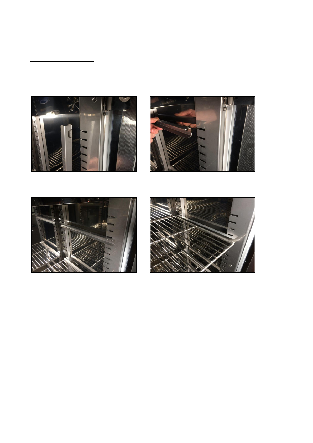
3.1. Installation of shelves ...........................................................................................................................10
3.2. Condensation in the chamber...............................................................................................................13
3.3. Remarks on the placement of samples.................................................................................................13
3.4. Closing chamber door...........................................................................................................................13
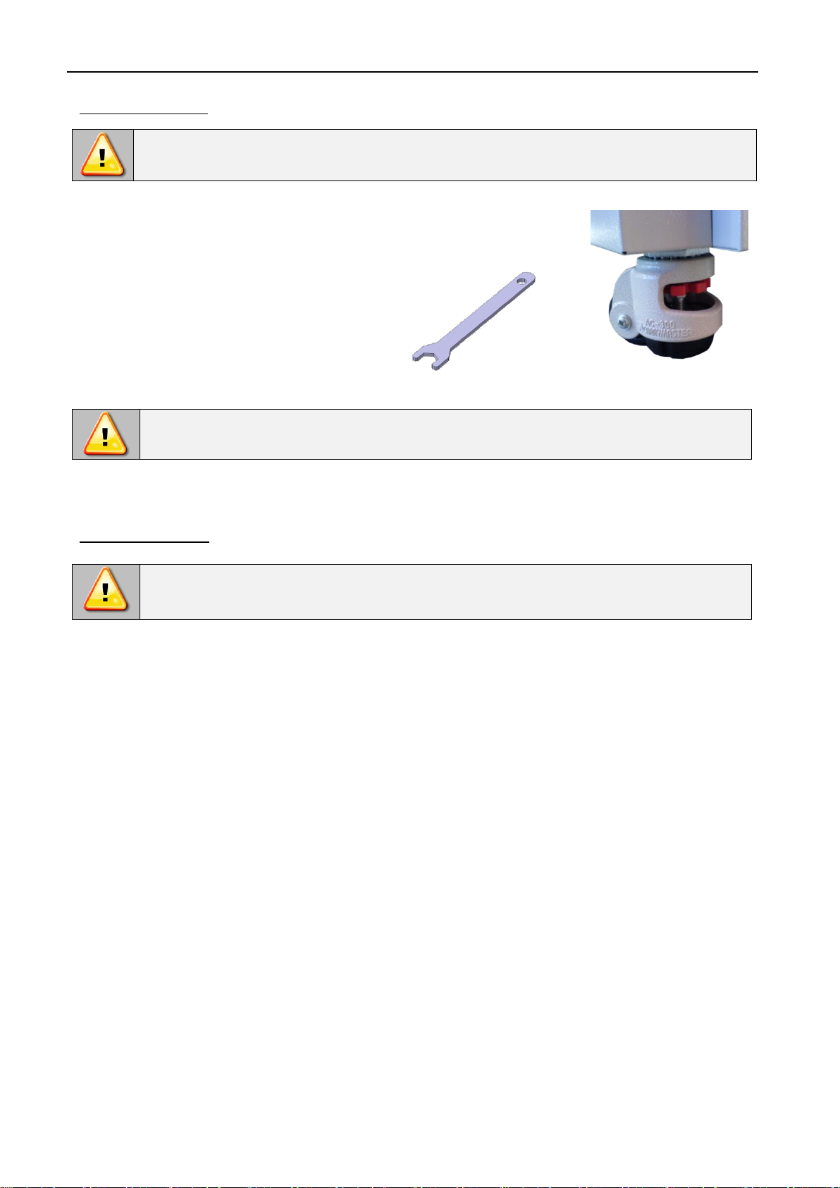
3.5. Anchoring of the equipment..................................................................................................................14
4. DESCRIPTION OF THE DEVICE..................................................................................................................15
4.1. Design of ST / CHL devices..................................................................................................................15
4.2. Design of ILW devices..........................................................................................................................18
5. DEVICE EQUIPMENT (standard and optional)..........................................................................................20
5.1. Internal glass door (optionally for ST / CHL, standard for ILW).............................................................20
5.2. External glass door (optionally for ST/CHL)..........................................................................................20
5.3. External door with viewing window (optionally for ILW)........................................................................20
5.4. Internal socket (optionally for ST, CHL, ILW)........................................................................................21
5.5. Door lock (standard for ST, CHL, ILW).................................................................................................21
5.6. Access port for external sensor (standard for ST, CHL, ILW)...............................................................21
5.7. Open door alarm (standard for ST, CHL, ILW) .....................................................................................22
5.8. Internal LED light (standard for ST, CHL, optionally for ILW) ...............................................................22
5.9. USB port (standard for ST, CHL, ILW)..................................................................................................22
5.10. Phytotron FIT (optionally for ST and ILW) ............................................................................................23
5.11. Display battery backup (optionally for ST, CHL, ILW)...........................................................................24
6. DEVICE OPERATION...................................................................................................................................25
6.1. External memory (USB flash drive).......................................................................................................25
6.2. First boot...............................................................................................................................................25
6.3. Using the keypad..................................................................................................................................25
6.4. User logging in......................................................................................................................................26
6.5. Main screen.................................................................................................................................27
6.5.1. Information panel..............................................................................................................................28
6.5.2. The meaning of icons and symbols..................................................................................................30
6.5.3. Upper expandable and configurable menu.......................................................................................32
6.5.4. Quick Note –user’s message .................................................................................................33
6.5.5. Alarm bar..........................................................................................................................................34
6.6. Quick Program......................................................................................................................................34
6.7. Programs.....................................................................................................................................36
6.7.1. Creating / editing a program.............................................................................................................37
6.7.2. Segments edition..............................................................................................................................38
6.7.3. Phytotron FIT (optionally for ST and ILW)*.......................................................................................40

Instruction manual ST, CHL, ILW SMART PRO
4
6.7.4. Summary of segments......................................................................................................................42
6.7.5. Protection class................................................................................................................................43
6.7.6. Temperature protection....................................................................................................................43
6.7.7. Priority..............................................................................................................................................44
6.7.8. Loop .................................................................................................................................................44
6.7.9. Defrosting program (only for CHL 1-6, CHL 500, CHL 700, CHL 1200, CHL 1450) 1,2.....................44
6.8. Starting the program.............................................................................................................................45
6.8.1. The first way.....................................................................................................................................45
6.8.2. The second way...............................................................................................................................47
6.9. Quick change of parameters.................................................................................................................48
6.9.1. Quick change of set temperature .....................................................................................................48
6.9.2. Quick change of set time..................................................................................................................49
6.9.3. Quick change of fan efficiency (only for ILW, ST 1-6, CHL 1-6).......................................................50
6.10. Schedules...................................................................................................................................51
6.10.1. Creating / editing a schedule............................................................................................................52
6.10.2. Starting a schedule...........................................................................................................................55
6.11. Statistics ......................................................................................................................................57
6.12. Data record..................................................................................................................................58
6.12.1. Graph ...............................................................................................................................................59
6.12.2. Data storage directly on a USB flash drive.......................................................................................60
6.13. Event log .....................................................................................................................................61
6.14. Info ..............................................................................................................................................64
6.15. Users ...........................................................................................................................................65
6.15.1. Creating / editing a user ...................................................................................................................65
6.15.2. Account types and their limits...........................................................................................................66
6.16. User settings panel......................................................................................................................68
6.16.1. Unlocking the touch screen..............................................................................................................69
6.17. Time ............................................................................................................................................70
6.18. Alarms.........................................................................................................................................71
6.18.1. STM function....................................................................................................................................72
6.18.2. Mute option.............................................................................................................................74
6.19. Network.......................................................................................................................................74
6.20. E-mail reports ..............................................................................................................................76
6.21. Automatic defrosting function (optionally for ST 1-6, ST 500-1450, CHL 1-6, CHL 500-1450, ILW,
standard for ST 500 M-1450 M i CHL 500 M-1450 M)*1....................................................................................78
6.22. Temperature –additional temperature sensor Pt 100 (option).....................................................79
6.23. Corrections...................................................................................................................................80

Instruction manual ST, CHL, ILW SMART PRO
5
7. INTERFACE..................................................................................................................................................81
7.1. MODBUS TCP......................................................................................................................................81
8. TEMPERATURE PROTECTION...................................................................................................................81
8.1. Temperature protection class ...............................................................................................................81
9. CONNECTING THE DEVICE TO A COMPUTER.........................................................................................82
10. OPERATION OF THE COOLING SYSTEM..................................................................................................82
11. CLEANING AND MAINTENANCE OF THE DEVICE...................................................................................83
11.1. Exterior cleaning...................................................................................................................................83
11.2. Interior cleaning....................................................................................................................................83
11.3. Cleaning the touch screen....................................................................................................................86
11.4. Consumables........................................................................................................................................87
12. ADVICE ON HOW TO SAFELY STORE THE DEVICE................................................................................87
13. TROUBLESHOOTING..................................................................................................................................87
13.1. Possible defects....................................................................................................................................88
14. WARRANTY CONDITIONS..........................................................................................................................89
15. RATING PLATE............................................................................................................................................90
16. TECHNICAL DATA.......................................................................................................................................91
16.1. ST, CHL devices...................................................................................................................................91
16.2. ST M, CHL M devices with monoblock.................................................................................................92
16.3. ST, CHL multi-chamber devices...........................................................................................................93
16.4. ILW devices..........................................................................................................................................96
17. DECLARATIONS OF CONFORMITY...........................................................................................................97

Instruction manual ST, CHL, ILW SMART PRO
6
1. INTENDED USE AND IMPORTANT INFORMATION FOR THE USER
ST thermostatic cabinets, CHL refrigerators and ILW cooled incubators are laboratory devices designed for incubation
and storage of samples at following temperature ranges:
•thermostatic cabinets ST: +3°C … +70°C
•laboratory refrigerators CHL: 0°C … +15°C
•laboratory incubators ILW: -10C (option)/0°C... +100°C
Thermostatic cabinets and incubators have both heating and cooling systems and forced air convection. Laboratory
refrigerators have only a cooling system. All devices are controlled by a precise SMART PRO controller, thanks to
which the set temperature is maintained with good fluctuation and variation. ST thermostatic cabinets and CHL
refrigerators are also available in multi-chamber versions, in which each chamber is independently controlled - this
manual also applies to devices of this type.
The meaning of information symbols
This symbol means that failure to follow the instructions could endanger people's health or life, or
damage the device. The manufacturer is not liable for damages resulting from non-compliance with
the instructions contained in the manual.
A flammable coolant is used in the cooling system. If the cooling system is damaged, ventilate the
room carefully and remove all open flames near the unit.
Warning for devices equipped with UV fluorescent lamps: take special care during work, avoid
exposure of the hands and eyes to ultraviolet radiation. This radiation can cause eye damage
(conjunctivitis) and skin changes (redness, cancer lesions, etc.). It is recommended not to open the device
chamber if UV light is on. The user should be equipped with personal protective equipment (protective
gloves, safety glasses).
This symbol indicates helpful tips.
To guarantee your security and the longevity of the unit, please comply with the following rules:
1.
The unit cannot be installed:
•outside,
•in damp places or places which can be easily flooded,
•near flammable or volatile substances,
•near acids or in corrosive environments.
2.
It is forbidden to:
•store inflammable or volatile substances inside the unit,
•touch live parts of the unit,
•operate the unit with wet hands,
•put water vessels on the unit,
•climb on the unit,
•overload the shelves (the maximum load is described in technical data).
3.
You should:
•place samples in such a way to provide proper air circulation in the chamber,
•open the door for the shortest period of time to reduce temperature fluctuations,
•secure samples from being blown out by the chamber fan e.g powdery samples,
•always check that the doors are closed correctly,
•use only mains with earth to avoid electric shocks,
•unplug the power cable holding the protective cover and not the cable itself,

Instruction manual ST, CHL, ILW SMART PRO
7
•disconnect the unit from the mains before undertaking any repairs or maintenance work (in order to not
lose the warranty during its duration, all repairs should be carried out by an authorized service),
•protect the power cable and the plug from any damage,
•disconnect the power plug before moving the unit,
•disconnect the power plug if the device will not be used for a long period of time,
•disconnect the unit and protect it from reconnecting if it has any visual fault.
Failure to comply with the above recommendations may result in damage to the device or deterioration of
technical parameters, as well as loss of warranty.
2. PACKAGE CONTENTS
Thermostatic cabinets (ST) and laboratory refrigerators (CHL) in SMART PRO version are delivered with:
Device
ST/CHL
Capacity
1
2
3
4
5
6
500
700
1200
1450
Shelves [pcs.]
2
2
2
3
3
3
3
3
6
6
Slides [pcs.]
4
4
4
6
6
6
6
6
12
12
Bottom shelves [pcs.]
x
1
1
1
1
1
x
x
x
x
Slides for bottom shelves [pcs.]
x
2
2
2
2
2
x
x
x
x
Power cord [pcs.]
1
1
1
1
1
1
INTEGRATED
Rubber cap [pcs.]
1
1
1
1
1
1
1
1
1
1
Key for door lock [pcs.]
2
2
2
2
2
2
2
2
4
4
Ethernet cable [pcs.]
1
1
1
1
1
1
1
1
1
1
Lab Desk program (in the internal memory
of the equipment)
1
1
1
1
1
1
1
1
1
1
Wrench (13mm) for wheels adjustment
[pcs.]
x
x
x
x
x
x
x
x
1
1
Quality Control Certificate [pcs.]
1
1
1
1
1
1
1
1
1
1
Cooled incubators (ILW) in SMART PRO version are delivered with:
Device
ILW
Capacity
53
115
240
400
750
Shelves [pcs.]
2
2
3
3
5
Slides [pcs.]
4
4
6
6
10
Power cord [pcs.]
1
1
1
1
1
Rubber cap [pcs.]
1
1
1
1
1
Key for door lock [pcs.]
2
2
2
2
2
Ethernet cable [pcs.]
1
1
1
1
1
Lab Desk program (in the internal memory
of the equipment)
1
1
1
1
1
Wrench (13mm) for wheels adjustment [pcs.]
x
x
x
1
1
Quality Control Certificate [pcs.]
1
1
1
1
1

Instruction manual ST, CHL, ILW SMART PRO
8
3. BEFORE THE FIRST USE
The manufacturer sends the device protected by cardboard profiles and foil. The device should be transported in an
upright position and the package should be secured against sliding during transport.
While carrying the unit, do not tilt it to one side more than 45° from the upright position, as there is
a high probability of damaging the compressor. If it is necessary to tilt it to one side more than 45°,
then after placing it, please wait about 3 hours before connecting the unit to the mains.
After transporting the device at a temperature below 10°С, wait at least 2 hours before connecting it
to the mains.
On the surface of unit’s components made of stainless steel, slight discoloration may occur. It is a result of the
technologies used in the production of metal sheet in accordance with the requirements of PN-EN 10088-2 standard
and it is not a defect of the unit.
The place of installation of the unit should meet the following conditions:
•ambient temperature +10°C...+28°C, for models with glass door +10°C...+25°C,
•recommended relative humidity of the ambient air up to 60%,
•the unit has not been designed to work in highly dusty environments,
•ensure proper ventilation in the room,
•the device should be placed on a hard and stable surface,
•the unit should be placed at least 100mm away from the walls,
•the height of the room must be at least 300mm greater than the height of the unit,
•the unit is not designed to be built-in,
•the place of installation of the device should be equipped with a socket with parameters suitable for the
device.
If you don’t comply with the above recommendations, the unit may get broken or it may worsen the technical
parameters such as:
•temperature fluctuation,
•temperature variation,
•power consumption,
•icing of evaporator
and may result in loss of warranty.
After receiving the device, visually assess its condition and equipment in the presence of the
person delivering the goods. A courier company is responsible for any damage caused during
transport.

Instruction manual ST, CHL, ILW SMART PRO
9
Wheels / leveling feet
The device has been equipped with wheels or leveling feet. After placing the unit at its destination,
secure the device against movement by locking the wheels. In the case of feet, after placing the
device in the destination, they should be leveled.
If the device is equipped with wheels, they must be locked and leveled (wheels in ST
1200 M, ST 1450 M, CHL 1200 M, CHL 1450 M, ILW 750 cannot be leveled). For this
purpose use the red knob mounted in the wheel housing. At the beginning, the knob can
be turned by hand, if it encounters resistance, use a 13 size wrench.
If the device is to be placed on a table (option) or frame (option) which is equipped with the wheels with a lock, the
wheels MUST be locked after placing the table / frame in its final destination.
Electric installation
Power supply of the equipment is indicated on a rating plate on the unit. Connect the device to a
socket with ground in order to avoid electric shocks in case of the unit’s failure.
The installation should be protected by a 16A slow-blow fuse and equipped with a residual current device.
Leveling wheels are ONLY for positioning the device at its destination. They can not be used to
transport the device!

Instruction manual ST, CHL, ILW SMART PRO
10
3.1. Installation of shelves
In the ST 1-6, CHL 1-6 models
To install the shelf or to change its position, follow these steps:
Install the shelf slide at the selected height by inserting it into proper slots on the wall of the device. Do the same with
the slide on the opposite wall.
Slide the shelf into the installed shelf slides. Now, the shelf is correctly installed!
To remove a shelf, perform the above steps in reverse order. To remove the shelf slide from the slots, lift it up and slide
it towards the rear of the chamber.

Instruction manual ST, CHL, ILW SMART PRO
11
In the ST 500 - 1450, ST 500 M - 1450 M, CHL 500 –1450, CHL 500 M - 1450 M models
To install the shelf or to change its position, follow these steps:
Install the shelf slide at the selected height by inserting it into proper slots on the wall of the device. Do the same with
the slide on the opposite wall.
Slide the shelf into the installed shelf slides. Now, the shelf is correctly installed!
To remove a shelf, perform the above steps in reverse order.

Instruction manual ST, CHL, ILW SMART PRO
12
In the ILW models
To install the shelf or to change its position, follow these steps:
Install the shelf slide at the selected height by inserting it into perforations on the wall of the device. Do the same with
the slide on the opposite wall.
Slide the shelf into the installed shelf slides. Now, the shelf is correctly installed!
To remove a shelf, perform the above steps in reverse order.

Instruction manual ST, CHL, ILW SMART PRO
13
3.2. Condensation in the chamber
If the set temperature is much lower than the ambient temperature, condensation may occur, which will cause
accumulation of the water at the bottom of the chamber. The amount of accumulated water depends on the following
factors:
•the difference between the ambient temperature and the temperature in the chamber,
•frequency of door openings,
•temperature of the samples.
Too high relative humidity in the chamber can cause icing of the cooling element, and thus reduce the
cooling efficiency and increase power consumption.
Cartons, sponges and other hygroscopic materials should not be used to store samples, as they may increase the
humidity in the chamber.
3.3. Remarks on the placement of samples
To provide proper air circulation and stable conditions in which the samples are stored in the chamber, it is necessary
to keep the following rules:
•the max height of the samples should not exceed 1/3 of the space between the shelves,
•approx. 1/3 of the width and depth of the shelf should remain empty, while the distances between the
samples, as well as between the samples and the wall should be approximately equal.
The picture below is an example of the placement of samples in the chamber.
Hmax
H
Hmax
a
uv w
xy z
b
u+v+w > 1/3 a
x+y+z > 1/3 b
Hmax = 2/3H
u v w
x y z
H
≅
≅ ≅
≅
Front view
Top view
Shelf
Following the above rules will provide best optimal parameters of temperature fluctuation and variation.
3.4. Closing chamber door
All units have been equipped with a gasket and open door sensor. If the door has not been closed properly, an audible
and visual alarm will start. You can set delay door alarm by: 30s, 1 min, 2 min, 5 min or 10 min (see Section 6.18).
If water accumulates at the bottom of the chamber, wipe the bottom of the chamber with a dry cloth.

Instruction manual ST, CHL, ILW SMART PRO
14
3.5. Anchoring of the equipment
In the case of high equipment (ST 500, ST 500 M, CHL 500, CHL 500 M, ST 700, ST 700 M, CHL 700,
CHL 700 M, ST 1200, ST 1200 M, CHL 1200, CHL 1200 M, ST 1450, ST 1450 M, CHL 1450, CHL 1450
M) and multi-chamber units they must be anchored to the wall with suitable fixings (the anchoring kit is
supplied with the device). This prevents the unit from falling over. Lack of anchoring may result in
damage to the device and in extreme cases may endanger the health or life of the person who
using the device.
Rear view
1. Install the mounting brackets (2) to the holes mar-
ked (1) on the back of the device using the sup-
plied screws and nuts. Handles can be set up or
sideways.
2. Place the equipment at the destination.
3. Use the 6 mm wall plugs adapted to the
anchoring point to attach the holders. Elongated
mounting hole in the bracket 10x10.
2
1

Instruction manual ST, CHL, ILW SMART PRO
15
1
10
9
8
2
4
3
5
6
7
11
4. DESCRIPTION OF THE DEVICE
SMART PRO models are equipped with a PID microprocessor temperature controller and a 7 inch colour touch screen
with a resolution of 800x480.
4.1. Design of ST / CHL devices
Below there’s a picture of ST model (exemplary photo) with a description of the important components of the device.
CHL model looks identical.
Front view
1) rating plate
2) temperature sensors
3) shelf
4) access port ø30mm for external
sensor
5) adjustable feet
6) external solid door
7) fan
8) key lock
9) touch control panel
10) USB port
11) open door sensor

Instruction manual ST, CHL, ILW SMART PRO
16
1
5
4
2
3
6
Rear view
1) main switch
2) condenser
3) cooling system
4) fuse
5) main power socket C14
6) LAN port

Instruction manual ST, CHL, ILW SMART PRO
17
2
1
5
4
3
Rear view (ST/CHL 500 M - 1450 M models)
1) anchoring handle
2) integrated power cable
3) fuse
4) main switch
5) LAN port

Instruction manual ST, CHL, ILW SMART PRO
18
1
8
2
7
3
4
6
9
5
12
11
10
4.2. Design of ILW devices
Below there’s a picture of ILW 115 model (exemplary photo) with a description of the important components of the
device.
Front view
1) rating plate
2) access port ø30mm for external
sensor
3) internal glass door
4) shelf
5) condenser housing
6) external solid door
7) temperature sensor
8) fan
9) open door sensor
10) touch control panel
11) USB port
12) handle door with key

Instruction manual ST, CHL, ILW SMART PRO
19
1
5
4
3
2
Rear view
1) main switch
2) adjustable feet
3) LAN port
4) fuse
5) main power socket C20

Instruction manual ST, CHL, ILW SMART PRO
20
5. DEVICE EQUIPMENT (STANDARD AND OPTIONAL)
5.1. Internal glass door (optionally for ST / CHL, standard for ILW)
Internal glass door is an optional equipment in ST thermostatic cabinets and CHL
laboratory refrigerators. For ILW cooled incubators it’s a standard equipment. To open and
close the door use the plastic handle attached to the glass.
During operation, when the temperature inside the chamber is high, do not touch the internal
components and glass doors, as there is a risk of burns. Use protective gloves to protect yourself
against the effects of burns from hot components.
5.2. External glass door (optionally for ST/CHL)
External glass door is an optional equipment in ST thermostatic cabinets and CHL laboratory refrigerators.
Due to external glass door the temperature range in ST thermostatic cabinets in SMART PRO
version is reduced from 70°C to 40°C.
5.3. External door with viewing window (optionally for ILW)
The external door with a viewing window is an optional equipment for ILW cooled cincubators.
We do not recommend installing and removing internal glass door. Incorrect assembly or disassembly may
result in damage to the glass and injury to the user.
Other manuals for SMART ST 1
1
This manual suits for next models
44
Table of contents
Other POL-EKO Laboratory Equipment manuals
Popular Laboratory Equipment manuals by other brands

WILKINS
WILKINS ZW209 Installation, Troubleshooting, Maintenance Instructions

Phihong
Phihong POE20D-1AF-R quick guide

Siemens
Siemens ADVIA 2400 Maintenance procedures

Thermo Scientific
Thermo Scientific 3960 Operating and maintenance manual

IKA
IKA HRC 2 basic operating instructions

EIJKELKAMP
EIJKELKAMP 08.02 SAND / KAOLIN BOX operating instructions