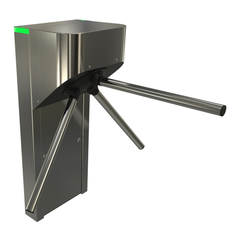
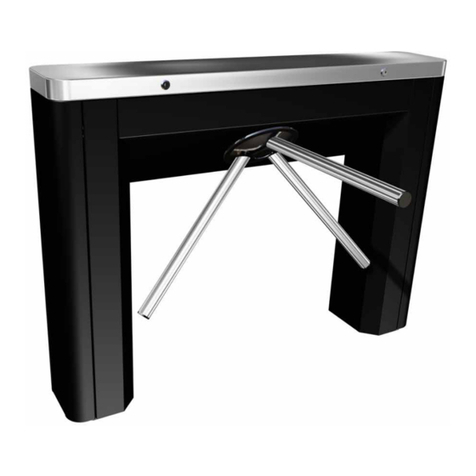
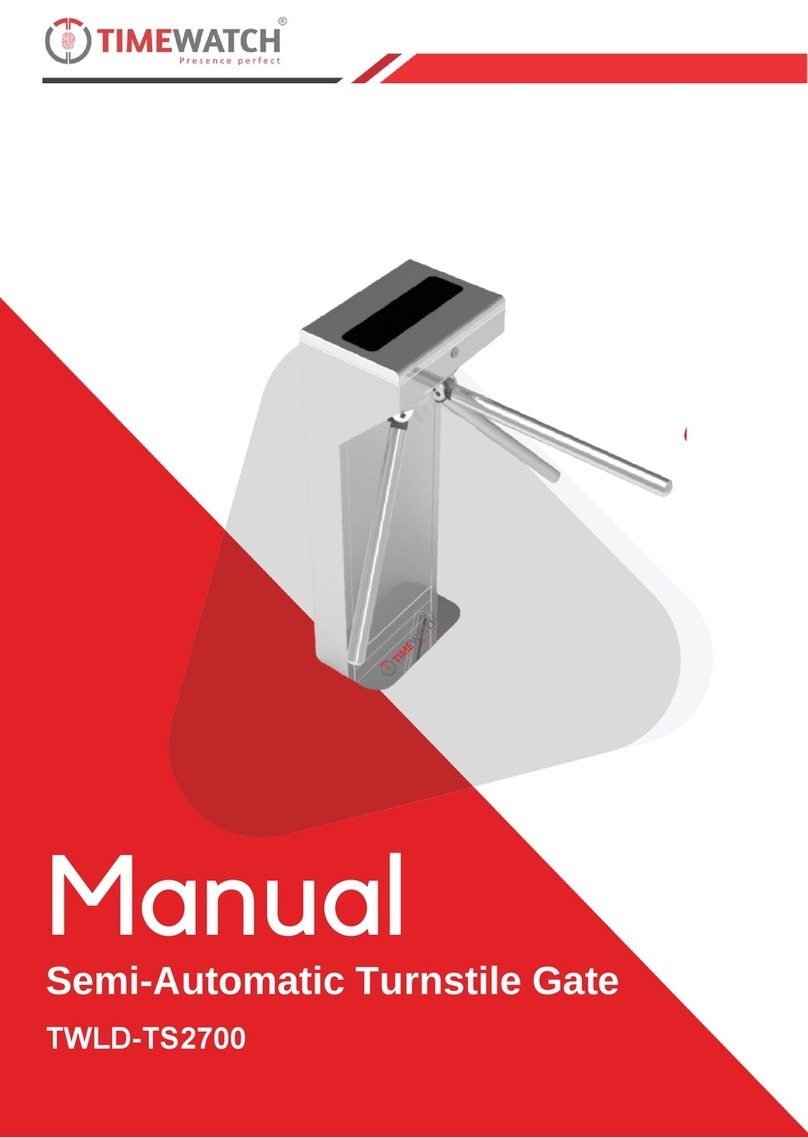
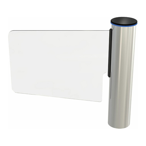
Automatic Systems SL930 User manual

The information contained in this document is the property of Automatic Systems and is confidential. The recipient is forbidd en to use it for any purpose other
than for the use of the products or the execution of the project to which they refer or to communicate it to third parties without the prior written consent of
Automatic Systems. Document subject to change without advance notification.
SL93x + PPV323 + TBV327-MT-EN p. 1/40
USER MANUAL
Rev 7
(Translated from French original notice)
GLASS SWING GATE
SL930 –SL931 –SL932
PPV323
GLASS
LOW-HEIGHT
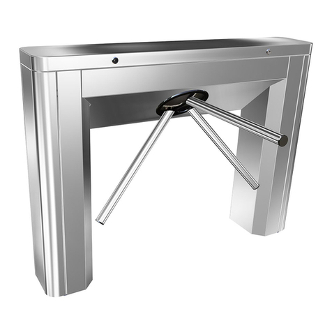
TURNSTILE
TBV327

The information contained in this document is the property of Automatic Systems and is confidential. The recipient is forbidd en to use it for any purpose other
than for the use of the products or the execution of the project to which they refer or to communicate it to third parties without the prior written consent of
Automatic Systems. Document subject to change without advance notification.
SL93x + PPV323 + TBV327-MT-EN p. 2/40
Document changes
Change
No.
Date
Written
by
Checked by
Subject
00
Dec. 12,
2006
MFy
RWK + JB
Initial version
01
April 23,
2007
MFy
- Page 16 (locking): "locked under voltage".
- Page 27 (parameter 60°, 90°, rotating): add
range and default value.
- Page 31 (Input 2): "Pitch of encoder 80".
- Page 26 (point 3): "remove the screws
(31)".
- Page 5 (1st point): "Folded and soldered
stainless steel plate housing".
02
Jun 25, 2007
MFy
- Pages 11, 13, 15, 19: replace the terms
"suction device" and "suction mechanism"
by "hold magnet".
- Pages 15 & 36: translate electric diagrams
in English.
03
2010-06-11
MFy
RWK+HB+DL
- Complete revision for adaptation to the
modification realized on the equipment.
04
2010-07-01
MFy
- Tec. Spec: replace flow by opening time of
the obstacles.
- Non-return lock option for TBV only.
05
2010-07-02
MFy
RH
- Installation: Last points of the Fixing
procedure transferred to Electrical
connections and Commissioning chapters.
- Preventive maintenance: check power
leakage and evacuation.
06
2011-01-17
MFy
- SL932 added in:
·Title p1,
·Table ch.2.1,
·Installation plan ch.3.2,
·Spare parts ch.5.4,
·EC certificate ch.7.
07
2012-01-09
MFy
- Ch. 2.1: MCBF, IP, CE, DAS added.

The information contained in this document is the property of Automatic Systems and is confidential. The recipient is forbidd en to use it for any purpose other
than for the use of the products or the execution of the project to which they refer or to communicate it to third parties without the prior written consent of
Automatic Systems. Document subject to change without advance notification.
SL93x + PPV323 + TBV327-MT-EN p. 3/40
Table of Contents
1. SAFETY INSTRUCTIONS 4
2. DESCRIPTION 5
2.1. Technical Specifications 5
2.2. Location of the components 6
3. INSTALLATION 7
3.1. Storage 7
3.2. Installation plans 8
3.3. Fixing the equipment to the floor 11
3.4. Electrical connections 12
3.5. Commissioning 14
4. PRINCIPLE OF OPERATION 15
4.1. Locking 16
4.2. Position encoder 17
4.3. Safety 17
5. MAINTENANCE 18
5.1. Removing the housing 18
5.2. Turning the equipment ON/OFF 19
5.3. Preventive maintenance 19
5.4. Spare parts 20
5.5. Adjusting the locking sensor 21
5.6. Adjusting the obstacle closed point 22
5.7. Setting the movement limit stops (5, p7) 22
5.8. Fitting and adjusting the locking mechanism 23
5.9. Replacing an obstacle 26
5.10. Control UNIT 27
5.11. Error messages 33
5.12. Trouble shooting 34
5.13. Disposal / Destruction 35
6. ELECTRICAL DIAGRAMS 36
7. DECLARATION OF CONFORMITY 39

The information contained in this document is the property of Automatic Systems and is confidential. The recipient is forbidd en to use it for any purpose other
than for the use of the products or the execution of the project to which they refer or to communicate it to third parties without the prior written consent of
Automatic Systems. Document subject to change without advance notification.
SL93x + PPV323 + TBV327-MT-EN p. 4/40
1. SAFETY INSTRUCTIONS
The SL93x, PPV323 and TBV327 gates and turnstiles are intended for the access control
of users and cannot be otherwise used without risk for the user or for the integrity of the
equipment.
They are intended for light traffic applications (cf. technical specifications, ch.2.1. )
It is mandatory to let the equipment complete its opening and closing cycles
automatically (without pushing the obstacle) to avoid untimely out of order.
All operations on the equipment must be carried out by qualified personnel. Any
unauthorized operation, or operation carried out by a technician not qualified on this
product, voids the manufacturer’s guarantee automatically.
Access to the mechanism must be limited to personnel aware of the electrical and
mechanical risks that are incurred by negligent action.
If possible, disconnect the electrical supply before opening the enclosure.
Otherwise, turn the power off by means of the circuit breaker located on the power board
(ch.5.2. ).
WARNING: In both cases, wait 5 minutes before working inside the equipment
(capacitors discharge)!
Any internal element likely to be put under voltage or to move must be handled with
caution.
The equipment is configured in a “minimal risk” mode for its users. Any changes to the
parameters must be carried out with full knowledge of the facts by qualified personnel
and are not the responsibility of Automatic Systems.

The information contained in this document is the property of Automatic Systems and is confidential. The recipient is forbidd en to use it for any purpose other
than for the use of the products or the execution of the project to which they refer or to communicate it to third parties without the prior written consent of
Automatic Systems. Document subject to change without advance notification.
SL93x + PPV323 + TBV327-MT-EN p. 5/40
2. DESCRIPTION
2.1. Technical Specifications
Folded and welded AISI 304 stainless steel sheet housing.
Internal frame protected with epoxy coating.
Passage obstacle in clear toughened glass, thickness: 10 mm.
Electrical supply: single phase, 230 VAC, 50 Hz (not to be connected to a floating network or to high
impedance earthed industrial distribution network).
Consumption: 0.12 A in closed and locked position,
0.50 A when turning,
0.90 A while locking.
Automatic obstacle unlocking on power failure.
Variable speed controller ensures rapid obstacle movements at the start of movement and
deceleration at end of movement.
Obstacle position determined by position encoder.
Operating temperature: -20(*) to +50°C (*Thanks to the heat generated by the powered
internal equipment).
RH < 95%, without condensation.
Minimum opening time of the obstacles (adjustable): 2.5 seconds.
Net weight (kg):
MCBF (Mean Cycles Between Failures), when respecting recommended maintenance:
1,000,000 cycles
IP 43
EC compliant.
DAS Certified (Powered Security Device) in accordance with Fire Safety NF S 61-937
standard
Gates and turnstiles control pedestrian access in both directions.
By definition, Direction A is the direction in which the controls are located on the right of the
user (=> obstacle opening in the clockwise direction).
PPV323
SL930
1 m
SL930
1.2 m
SL931
1.4 m
SL931
1.7 m
SL931
1.9 m
SL932
0.9m
TBV327
Column
62
62
62
77
77
77
62
77
Panels
17
19
24
29
36
40
17
3 x 8.4
Total
79
81
86
106
113
117
79
102
Direction A = clockwise

The information contained in this document is the property of Automatic Systems and is confidential. The recipient is forbidd en to use it for any purpose other
than for the use of the products or the execution of the project to which they refer or to communicate it to third parties without the prior written consent of
Automatic Systems. Document subject to change without advance notification.
SL93x + PPV323 + TBV327-MT-EN p. 6/40
2.2. Location of the components
1
11
15
10 (behind)
2
7
5
4
12
13
3
9
8
14
6
1. Mounting base (attached to the floor)
2. Main chassis (= equipment without obstacle)
3. Obstacle (= glass panel)
4. Conical coupling of the rotor to the motor
5. Movement limit stop (not on TBV)
6. Variable speed controller
7. Locking system
8. Position encoder
9. Power supply board
10. Control board
11. Regulated power supply
12. Obstacle support rotor
13. Additional obstacle support (for SL931 only)
14. Motor
15. Serial number

The information contained in this document is the property of Automatic Systems and is confidential. The recipient is forbidd en to use it for any purpose other
than for the use of the products or the execution of the project to which they refer or to communicate it to third parties without the prior written consent of
Automatic Systems. Document subject to change without advance notification.
SL93x + PPV323 + TBV327-MT-EN p. 7/40
3. INSTALLATION
The installation must be carried out in accordance with the safety instructions (p 4) and the
installation plan (p3.2. ).
3.1. Storage
Before installation, avoid all shocks to the equipment and place it in its original packing in a
dry place, protected from dust, heat and bad weather.
Storage temperature limits: -30 to +80°C

The information contained in this document is the property of Automatic Systems and is confidential. The recipient is forbidd en to use it for any purpose other
than for the use of the products or the execution of the project to which they refer or to communicate it to third parties without the prior written consent of
Automatic Systems. Document subject to change without advance notification.
SL93x + PPV323 + TBV327-MT-EN p. 8/40
3.2. Installation plans

The information contained in this document is the property of Automatic Systems and is confidential. The recipient is forbidd en to use it for any purpose other
than for the use of the products or the execution of the project to which they refer or to communicate it to third parties without the prior written consent of
Automatic Systems. Document subject to change without advance notification.
SL93x + PPV323 + TBV327-MT-EN p. 9/40

The information contained in this document is the property of Automatic Systems and is confidential. The recipient is forbidd en to use it for any purpose other
than for the use of the products or the execution of the project to which they refer or to communicate it to third parties without the prior written consent of
Automatic Systems. Document subject to change without advance notification.
SL93x + PPV323 + TBV327-MT-EN p. 10/40

The information contained in this document is the property of Automatic Systems and is confidential. The recipient is forbidd en to use it for any purpose other
than for the use of the products or the execution of the project to which they refer or to communicate it to third parties without the prior written consent of
Automatic Systems. Document subject to change without advance notification.
SL93x + PPV323 + TBV327-MT-EN p. 11/40
3.3. Fixing the equipment to the floor
1. Remove the 2 covers by removing the screws (50, p 26).
2. Unscrew the base (1, p 6) from the main chassis and secure it to the floor with the 3
expanding bolts supplied (Liebig B15/30 (A)). First drill 3 x 15 mm diameter holes to a
depth of 85 mm.
WARNING: It is essential to adapt the fastening hardware and the installation procedure to the
environment and the nature of the floor on which the gate will be positioned.
Installation must be validated by certified civil engineers.
The gate must be fastened to the floor before it is made available to the users!
Automatic Systems cannot be held responsible for any accident or damage to the gate due to the
fact that the gate was not adequately fastened to the floor.
3. Position the main chassis (2, p 6) over the base (1), with the sticker COTE DU
PASSAGE (= Passageway side) aligned as shown below, so that the control board (10,
p 6) remains accessible.
4. Fit the obstacle(s) to the frame (see ch.5.9. ).
5. Adjust the vertical alignment of the main chassis with the 3 bolts (B).
6. Tighten the 3 locknuts (C) to secure the main chassis to the base.
7. Cut the cable tie securing the locking mechanism (7, p 6).
A
C
B
A
C
V
B
1
2

The information contained in this document is the property of Automatic Systems and is confidential. The recipient is forbidd en to use it for any purpose other
than for the use of the products or the execution of the project to which they refer or to communicate it to third parties without the prior written consent of
Automatic Systems. Document subject to change without advance notification.
SL93x + PPV323 + TBV327-MT-EN p. 12/40
3.4. Electrical connections
WARNING: The operations must be undertaken in accordance with the safety warnings, ch.1.
In particular, the mains must be shut down before any of the work described below is begun.
Connections must be executed in accordance with the wiring diagrams provided inside the equipment,
which remain the reference.
Type of
cable
Connections
3G2.5²
Electrical power supply of
each equipment (230 V
single phase + ground +
differential breaker 30 mA
min for each equipment).
WARNING: High leakage
current.
=> Connection to the
ground imperative with a
1-mm² cable before
connecting the mains.
=> Do not connect
several equipments to the
same differential breaker.
2.5²
If the gates are powered
through long cables,
ensure the equipotential
bonding between the
gates forming a bank by
connecting them with a
1-mm² ground wire.
Δ 30
mA
Δ 30
mA
230 VAC - 50 Hz

The information contained in this document is the property of Automatic Systems and is confidential. The recipient is forbidd en to use it for any purpose other
than for the use of the products or the execution of the project to which they refer or to communicate it to third parties without the prior written consent of
Automatic Systems. Document subject to change without advance notification.
SL93x + PPV323 + TBV327-MT-EN p. 13/40
Type of
cable
Connections
Evacuation
command
(Fire):
If through a dry contact:
connect lower
connectors (Fire link)
with a Normally Closed
switch
AND
put the jumper in the
lower position.
Note: if there is no
evacuation command,
shunt these connectors.
If through a 24 V DC
command:
connect upper
connectors (0V and
+24")
AND
put the jumper in the
upper position.
Network
cable
Connect the opening
commands and eventual
Inputs/Outputs.
Refer to the electrical diagrams.
0 V
+ 24 V

The information contained in this document is the property of Automatic Systems and is confidential. The recipient is forbidd en to use it for any purpose other
than for the use of the products or the execution of the project to which they refer or to communicate it to third parties without the prior written consent of
Automatic Systems. Document subject to change without advance notification.
SL93x + PPV323 + TBV327-MT-EN p. 14/40
3.5. Commissioning
1. Connect the power supply to the equipment.
The obstacle will move, seeking its starting point.
2. Adjust the obstacle position (ch.5.6. ).
3. Check the control unit parameters (ch.5.10. ), in particular the speeds and opening angles.
4. Check the locking by pushing the obstacle.
5. Give a clockwise opening command.
6. Give a counter-clockwise opening command.
7. Check the mechanical stops in the clockwise and anti-clockwise directions.
8. Trigger a FIRE command and check if the obstacle opens.
9. Turn off the power and check that the obstacle unlocks.
10. Replace the covers.

The information contained in this document is the property of Automatic Systems and is confidential. The recipient is forbidd en to use it for any purpose other
than for the use of the products or the execution of the project to which they refer or to communicate it to third parties without the prior written consent of
Automatic Systems. Document subject to change without advance notification.
SL93x + PPV323 + TBV327-MT-EN p. 15/40
4. PRINCIPLE OF OPERATION
The references in this chapter refer to the illustrations on ch.2.2.
The Swing Gates and Turnstiles (named hereafter "Gates") are bidirectional pivoting access
control units that allow passage in both directions.
They have a steel central column (2) fixed to the floor containing the control board (10) and
the drive unit. The central column is equipped with 1 or 3 glass obstacles (3).
The gate is unlocked by an external command (pushbutton, card readers, etc.). According to the
selected mode, the obstacle then starts to turn automatically (in the authorized direction of
passage) or on light pressure.
The movement of the obstacle is transmitted by a geared motor driven by a variable speed
controller (6), which allows the opening and closing speed to be adjusted.
The opening angle can be set to 60° or 90° (SL93x) and 120° (TBV) in both directions.
The direction of rotation and the position of the obstacle are determined by a position encoder
(8).
The obstacle stays open for a period set by a parameter and then closes again automatically.
Movement sequence:
The obstacle opens at high speed (HS) from the starting point (= passage closed).
From an angle set by a parameter (parameter "HSP > LSP angle opening"), the
obstacle completes its movement at low speed (LSP).
The obstacle registers a stopping time (set by parameter) in the open position (the
opening angle can also be set by parameter).
The obstacle is maintained at low speed against the limit stop.
The obstacle closes again at high speed.
From a chosen angle (parameter "HSP > LSP angle closing", the obstacle completes its
movement at low speed (LSP).
When the obstacle reaches its closed position, the bolt is engaged.
Speed and angle parameters
Speeds, angles and delays are adjustable
and are identical for clockwise and counter-clockwise opening directions.
HSP > LSP angle opening
HSP > LSP angle closing
Opening angle clockwise
Closed
(= 0°)
Stop time
LSP
LSP
HSP
HSP
Direction A

The information contained in this document is the property of Automatic Systems and is confidential. The recipient is forbidd en to use it for any purpose other
than for the use of the products or the execution of the project to which they refer or to communicate it to third parties without the prior written consent of
Automatic Systems. Document subject to change without advance notification.
SL93x + PPV323 + TBV327-MT-EN p. 16/40
4.1. Locking
The locking mechanism (70) is activated by an electromagnet (71) with positive security
(locked under voltage).
When the obstacle reaches its closed position, the locking sensor (75) is activated by
detection of a vane (76). The electromagnet then moves the bolt into hole (77a) of plate (77),
locking the rotor (12). Locking is maintained by the electrical circuit between the hold magnet
(72) and the contact plate (73).
NON-RETURN OPTION (for TBV model only): During the opening in one direction, if the
obstacle is forced to open in the other direction, the electromagnet (68) moves the non-return
bolt (69) into hole (77b) of plate (77), locking the rotor (12).
The correct movement continues as soon as this reverse force is removed (without putting the
equipment out of service).
70
71
72
73
75
76
77
77a
77b
77
69
68
69

The information contained in this document is the property of Automatic Systems and is confidential. The recipient is forbidd en to use it for any purpose other
than for the use of the products or the execution of the project to which they refer or to communicate it to third parties without the prior written consent of
Automatic Systems. Document subject to change without advance notification.
SL93x + PPV323 + TBV327-MT-EN p. 17/40
4.2. Position encoder
The direction of rotation and the position of the obstacle are determined by a position
encoder (80), consisting of a vaned disk that turns with the motor shaft and passes through
2 sensors (81 and 82). This encoder does not need any adjustment.
4.3. Safety
During rotation, if the obstacle encounters an obstruction limiting its movement, it will
make several attempts to complete the current movement, after which the motor will be
powered off automatically if the resistance is still present (see parameter "Faults
numbers").
As long as the open command is maintained, the obstacle will not close.
When a second opening command is received in the same direction while the obstacle
is closing, it will re-open immediately.
When a Fire Detection (“FIRE”) command is received, the gate opens automatically (the
direction of opening is set by parameter "Opening CW/CCW in case of fire").
When there is a power failure, the gate is unlocked automatically and can then be
opened manually.
80
81
82

The information contained in this document is the property of Automatic Systems and is confidential. The recipient is forbidd en to use it for any purpose other
than for the use of the products or the execution of the project to which they refer or to communicate it to third parties without the prior written consent of
Automatic Systems. Document subject to change without advance notification.
SL93x + PPV323 + TBV327-MT-EN p. 18/40
5. MAINTENANCE
WARNING: The adjustment operations must be carried out in accordance with the safety
instructions (p 4).
5.1. Removing the housing
1. Remove all the screws (50).
2. Remove both elements of the housing.
50

The information contained in this document is the property of Automatic Systems and is confidential. The recipient is forbidd en to use it for any purpose other
than for the use of the products or the execution of the project to which they refer or to communicate it to third parties without the prior written consent of
Automatic Systems. Document subject to change without advance notification.
SL93x + PPV323 + TBV327-MT-EN p. 19/40
5.2. Turning the equipment ON/OFF
5.3. Preventive maintenance
Every 100,000 operations, or every 6 months, whichever comes first, check the following
points:
The security of all components (attachment to the floor, obstacle, motor, conical coupling
(4, p 6), etc.).
The state of the ground cable on the rotor (Fig. A).
The control signals.
The opening and closing speeds.
The obstacle opening and closing angles and positions.
The activation of the locking mechanism in the closed position.
The operation during a power outage (unlocking) and an evacuation order (opening).
Any output signals to optional peripheral equipment.
Clean the stainless steel surfaces and glasses by means of an appropriate product.
Fig. A: connection of the rotor to the ground
ON
OFF

The information contained in this document is the property of Automatic Systems and is confidential. The recipient is forbidd en to use it for any purpose other
than for the use of the products or the execution of the project to which they refer or to communicate it to third parties without the prior written consent of
Automatic Systems. Document subject to change without advance notification.
SL93x + PPV323 + TBV327-MT-EN p. 20/40
5.4. Spare parts
DESIGNATION
CODE
VALIDITY
PPV323
SL930
SL931
SL932
TBV327
Power supply 230V / 24VDC 2.5A (11, p 6)
E/6980/536
> 01/2007
x
x
x
x
x
Stainless steel hood
CRA-E01107
< 01/2007
x
x
x
Stainless steel hood
0/6980/549
> 01/2007
x
x
x
x
x
Fork sensor (75, p16 & 82, p17)
E/6980/531
> 01/2007
x
x
x
x
x
CPU board (10, p6)
E/6980/530
> 01/2007
x
x
x
x
x
Power supply board V3 (9, p 6)
E/6980/537
< 10/2009
x
x
x
x
x
Power supply board V5
0/6982/064
> 10/2009
x
x
x
x
x
Locking disc
0/6980/583
> 01/2007
x
x
x
x
x
Short locking finger in stainless steel
0/6982/069
> 08/2008
x
x
x
x
x
Long locking finger in aluminium
0/6982/068
< 08/2008
x
x
x
x
x
Electromagnet (71, p 16)
E/6980/540
> 01/2007
x
x
x
x
x
Motor assembly with encoder
E/6980/541
< 12/2008
x
x
x
x
x
Motor assembly with encoder
0/6982/065
> 12/2008
x
x
x
x
x
Brake
0/6980/386
< 01/2007
x
x
x
x
Control unit 240V without microprocessor
0/7000/855
< 01/2007
x
x
x
x
Microprocessor for CPU card
E/6980/546
< 01/2007
x
x
x
x
Mobile obstacle 1230 x 850 mm
OBV-E07050
> 01/2007
x
Mobile obstacle 1530 x 850 mm
OBV-E07030
> 01/2007
x
Mobile obstacle 1730 x 850 mm
OBV-E07049
> 01/2007
x
Mobile obstacle 480 x 640 mm
OBV-E07054
> 01/2007
x
Mobile obstacle 830 x 850 mm
OBV-E07014
> 01/2007
x
Mobile obstacle 1030 x 850 mm
OBV-E07047
> 01/2007
x
Mobile obstacle 960 x 640 mm
OBV-E02405
< 01/2007
x
Mobile obstacle 640 x 950 mm
OBV-E07052
> 01/2007
x
Obstacle mobile 740 x 850 mm
E/0875/023
>01/2007
x
Optocoupler
E/6980/539
> 01/2007
x
x
x
x
x
Stainless steel sheet
0/6980/542
> 01/2007
x
Stainless steel sheet with cutting
CRA-E01122
< 01/2007
x
x
x
Stainless steel sheet with cutting
0/6980/545
> 01/2007
x
x
x
Stainless steel sheet with cutting
0/6980/547
> 01/2007
x
Stainless steel sheet without cutting
CRA-E01124
< 01/2007
x
x
x
Stainless steel sheet without cutting
0/6980/546
> 01/2007
x
x
x
Stainless steel sheet without cutting
0/6980/548
> 01/2007
x
Transformer 240V/24V
0/6980/388
< 01/2007
x
x
x
x
Drive unit
0/7000/850
< 01/2007
x
x
x
x
Frequency inverter 230V (6, p 6)
E/6980/538
< 12/2008
x
x
x
x
x
Frequency inverter 230V
0/6982/066
> 12/2008
x
x
x
x
x
Suction disc (72, p 16)
E/6980/520
> 01/2007
x
x
x
x
x
No return bolt
0/6980/658
> 01/2007
x
Bolt assembly (p 23)
E/6980/542
> 01/2007
x
x
x
x
x
This manual suits for next models
4
Table of contents
Other Automatic Systems Turnstile manuals
Automatic Systems
Automatic Systems SmartLane User manual

Automatic Systems
Automatic Systems TriLane TL1 User manual

Automatic Systems
Automatic Systems TR491 User manual

Automatic Systems
Automatic Systems SMARTLANE SL 90X User manual

Automatic Systems
Automatic Systems TriLane TL2 User manual

Automatic Systems
Automatic Systems TriLane TL Series User manual
Automatic Systems
Automatic Systems SMARTLANE SL 90 Series User manual

Automatic Systems
Automatic Systems TR450 User manual