Dormakaba ALVARADO SUPERVISOR 5000 User manual

Alvarado Manufacturing Company, Inc.
12660 Colony Street, Chino, CA 91710
Phone: +1 (909) 591-8431
Fax: +1 (909) 628-1403
www.alvaradomfg.com
PUD3668R2-0
SUPERVISOR 5000
(SU5000)
Optical Turnstile with Bi-directional Motorized Barriers
User Guide

This page intentionally left blank.

Supervisor 5000 User Guide
Contents. ........................................................................................................................................................ 3
ETL Certi cation. ............................................................................................................................................ 3
Safety Precautions. ........................................................................................................................................ 4
Purpose Of This User Guide. ......................................................................................................................... 5
Intended Users. ........................................................................................................................................ 5
User Responsibilities. ............................................................................................................................... 5
SU5000 Overview........................................................................................................................................... 6
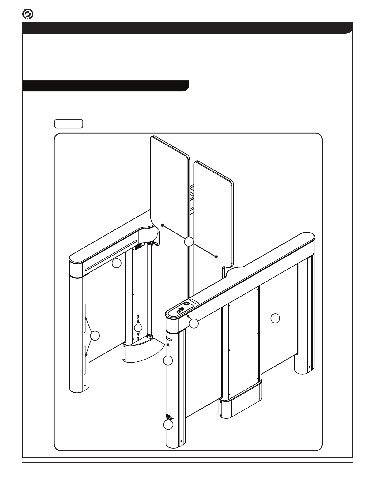
SU5000 Components - Exterior View. ...................................................................................................... 6
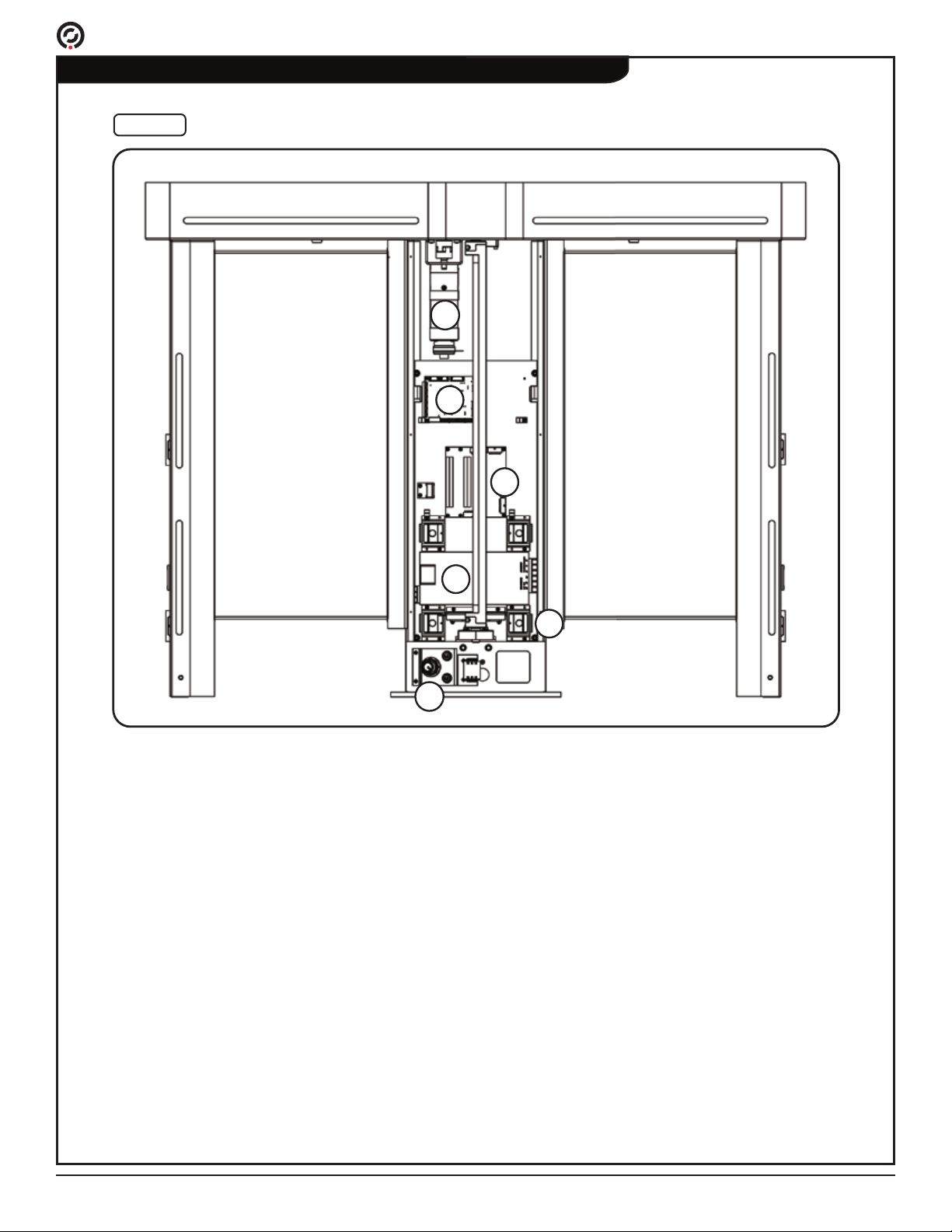
SU5000 Components - Center Portion Interior View. ............................................................................... 8
SU5000 Cabinets. .................................................................................................................................. 10
SU5000 Options. .................................................................................................................................... 13
Access Control Integration. .................................................................................................................... 14
SU5000 Functionality.................................................................................................................................... 15
Passage Modes...................................................................................................................................... 15
Setting Passage Modes.......................................................................................................................... 16
Bi-directional Traf c and Smart Use of Passage Modes. ....................................................................... 16
User Status Display. ............................................................................................................................... 18
Open / Close Status Light....................................................................................................................... 19
Operational Sounds................................................................................................................................ 20
SU5000 Operation........................................................................................................................................ 22
Powering On / Off. .................................................................................................................................. 22
Lane Key Control (Option)...................................................................................................................... 23
User Instructions..................................................................................................................................... 24
Turnstile Operations. .............................................................................................................................. 26
I/O Control. ................................................................................................................................................... 32
Inputs...................................................................................................................................................... 32
Outputs. .................................................................................................................................................. 35
SU5000 Con guration Preparation............................................................................................................... 38
Overview................................................................................................................................................. 38
New Installation Con guration Checklist. ............................................................................................... 38
Installing the Con guration Tools............................................................................................................ 39
Connecting a Laptop Directly to the Turnstile......................................................................................... 40
Operating System Con guration. ................................................................................................................. 41
Setting the Local System Time. .............................................................................................................. 43
Setting the Turnstile IP Address. ............................................................................................................ 44
Maintenance................................................................................................................................................. 46
Weekly Safety Check. .................................................................................................................................. 47
Troubleshooting............................................................................................................................................ 48
Revision History............................................................................................................................................ 50
Contents
This product is fully certi ed by a nationally recognized testing laboratory to UL 2593 and
CSA C22.2 #247. Unauthorized modi cation to this product in any way is prohibited.
ETL Certi cation

Supervisor 5000 User Guide
• For indoor use only.
• Use only skilled individuals to install and service the turnstile.
• DO NOT operate the turnstile if it has been damaged in any manner. If damaged, have the unit
repaired or adjusted by a skilled service person before use.
• DO NOT modify or alter the turnstile.
• Have skilled individuals maintain the turnstile according to a proper maintenance schedule.
• In access control applications, train all personnel that will be using the turnstile in the proper
method of operation. In addition, properly train new users as they are added to the system.
• DO NOT use non-Alvarado parts to repair a damaged turnstile.
• Power off the turnstile before connecting or disconnecting any communication or power wiring
to the turnstile.
• This turnstile can be used by children aged 12 and above, inexperienced persons, or
persons with reduced physical, sensory, or mental conditions, if such children or persons are
supervised, or have been provided instruction regarding the safe and proper usage. Children
shall not play with or around the turnstile.
• The turnstile shall be disconnected from its power source during service and when replacing
parts. The turnstile shall be disconnected from its power source before connecting or
disconnecting any communication or other activation/feedback control wires. If it is not possible
that the technician can check from any point to which he has access that the main power is
removed, a disconnection with a locking system in the isolated position shall be provided.
• Pour utilisation à l'intérieur seulement.
• Utilisez uniquement des personnes qualiées pour installer et entretenir le tourniquet.
• NE PAS faire fonctionner le tourniquet s'il a été endommagé de quelque façon. S'il est
endommagé, faire réparer ou ajuster l'unité avant l'utilisation par un(e) préposé(e) à l'entretien
qualié(e).
• NE PAS modier ou altérer le tourniquet.
• Le tourniquet doit être maintenu selon un calendrier d'entretien adéquat par des personnes
qualiées.
• Dans les applications de contrôle d'accès, former tout le personnel qui utilisera le tourniquet
selon la bonne méthode de fonctionnement. De plus, bien former les nouveaux utilisateurs à
leur intégration au système.
• NE PAS utiliser des pièces ne provenant pas du Alvarado pour réparer un tourniquet
endommagé.
• Suivez strictement les instructions de manutention pour déplacer ou soulever le tourniquet lors
de l'installation
• Éteignez le tourniquet avant de brancher ou de débrancher le câblage de communication ou le
câblage d'electricité.
Safety Precautions
WARNING The Supervisor 5000 may present a risk to persons and property if it is not
operated correctly. Therefore, this manual must be read in its entirety and
all safety and operations information must be adhered to. Note the following
precautions:

Supervisor 5000 User Guide
Purpose Of This User Guide
The Supervisor 5000 (“SU5000”) User Guide is an operational manual which describes the operational
features of Alvarado SU5000 optical turnstile product.
The manual is intended for use by owners, facility operators, and system integrators responsible for the
product, the facility access system and the employees, vendors and invitees that will use the equipment on
a day-to-day basis.
As owner or caretaker of the equipment, it is essential that you maintain your SU5000s and ensure safe
product use by the employees, vendors, and invitees that will be utilizing the product.
The operation of the SU5000s should be tested weekly to ensure the product is operating correctly. This
User Guide provides instructions for a Weekly Safety Check.
Intended Users
User Responsibilities

Supervisor 5000 User Guide
SU5000 Components - Exterior View
An overview of the major turnstile components is presented below [Fig. 1 & Fig. 2]. More information on
these components can be found later in the User Guide.
Fig. 1Fig. 1 SU5000 Components - Exterior ViewSU5000 Components - Exterior View
H
A
B
C
D
E
F
G
SU5000 Overview
The SU5000 is an optical turnstile that provides bi-directional access control in conjunction with a facility
access control system. The SU5000 utilizes tandem motorized barriers and integrated optical sensors to
control access. The optical sensors detect patrons, determine the direction of patron movement, and detect
both authorized and unauthorized users.

Supervisor 5000 User Guide
SU5000 Components - Exterior View (cont.)
A
B
C
D
User Status Display / Card Reader Location
The user status display provides visual instructions to users regarding the status of presented
credentials (based on data from the access control system) and visual notication of alarm
conditions.
Card readers are normally installed underneath the lid directly below the user status display.
Open / Closed Status Light
Open / closed status lights are mounted to the right-hand leg for each direction of entry. The lights
function similar toll booth lights, and notify the user of turnstile availability status.
Free Passage Sensors
Free passage sensors are located on both ends of the turnstile in the area indicated. Infrared
transmitters are on the secondary side of the turnstile. Infrared receiver sensors are on the Main side
of the turnstile.
In Free Pass mode, these sensors detect users as soon as they enter the turnstile, triggering the
barriers to open away from the user.
Operational Sensors
Operational sensors are located inside the top channel of the cabinet, running horizontally the length
of the cabinet. Infrared transmitters are on the secondary side of the turnstile. Infrared receiver
sensors are on the Main side of the turnstile.
Operational sensors have multiple purposes. These include the detection and monitoring of users
as they enter, pass through and exit the turnstile, and the detection of objects in the path of opening
barriers.
Safety Sensors
Safety Sensors are located in the center portion of the cabinet on both the entry and exit side of the
turnstile. Infrared transmitters are on the secondary side of the turnstile. Infrared receiver sensors
are on the Main side of the turnstile. Safety sensors are used to prevent the barriers from opening
and closing on a user.
Motorized Barriers
The motorized moving barriers are acrylic with a special abrasion resistant coating. Barriers are
offered in three heights: 35”, 46” or 69”. The barriers operate bi-directionally. Movement of the
barriers is accomplished through the integration of brushless DC motors, digital position encoders,
motor controllers and motor control software using closed loop position control.
Speaker
A speaker is mounted to each leg of Main and center cabinets. The speaker is used to play auditory
sounds and alarms.
Side Panels
Side Panels are acrylic with a special abrasion resistant coating.
E
F
G
H

Supervisor 5000 User Guide
I
J
K
M
L
N
Fig. 2Fig. 2 Center Portion Interior (Main Cabinet)Center Portion Interior (Main Cabinet)
SU5000 Components - Center Portion Interior View

Supervisor 5000 User Guide
Main Turnstile Controller & I/O Control Board
There is one CPU and one I/O control board per turnstile. The two boards are stacked inside the
Main cabinet. The I/O control board is the outward most accessible board and is the interface point
between the turnstile and the facility access control system. Passage activation and the various
other inputs and outputs available from the turnstile are accessed through the I/O control board
terminal strips. The main turnstile controller houses the CPU unit and various hardware ports, such
as USB, Ethernet, and HDMI.
Motor Controller Board
Each turnstile has two motor controller boards. Each motor controller board controls one of the
two turnstile motors. Low-voltage power and various data signals are also routed through motor
controller boards.
Motors
Each turnstile has two brushless DC motors (combined with planetary gearbox and electro-
mechanical brake) that operate the drive system moving the barriers.
Power Supply
There is a single 24V power supply installed in the Main / Center cabinet. This supply converts
primary power to 24V low-voltage power for motor operation. Motor controller boards reduce the 24V
power to 5V and 12V for main turnstile controller, optical sensor, and light operation.
Power Switch
There is one power switch installed per turnstile. The power switch is installed in the base of the
Main / Center cabinet on the secured side.
Safety Sensors
There are four safety sensors per cabinet.
I
J
K
M
L
N
SU5000 Components - Center Portion Interior View (cont.)

Supervisor 5000 User Guide
SU5000 Cabinets
There are three types of SU5000 cabinets used to create passage lanes: a Main Cabinet, a Secondary
Cabinet, and a Center (Expansion) cabinet. A single passage lane consists of a Main cabinet and a
Secondary cabinet [Fig. 3]. The Center cabinet is used to create additional passage lanes with the addition
of a single cabinet [Fig. 4].
Each cabinet has an unsecured and secured side. Alvarado follows what we call the “right-hand rule." User
status lights and card readers are always installed on the right-hand side as you enter the turnstile.
The center portion of the Main Cabinet contains
the turnstile CPU, I/O control board, motor and
motor controller board, power supply, safety
sensor receivers, one moving barrier, and a power
switch located at the base on the secured side.
The top channel of the Main Cabinet contains the
operational sensor receivers, a drive system, and
a User Status Display that communicates turnstile
status to the user. A card reader is normally
installed during installation underneath the lid
below the User Status Display.
Main Cabinet
Fig. 3Fig. 3 Single Lane CongurationSingle Lane Conguration
Secured
Side
Unsecured
Side
Secondary
Cabinet
Main
Cabinet
Power
Key
Switch
The center portion of the Secondary Cabinet
contains a motor and motor controller board,
safety sensor transmitters, and one moving barrier.
The top channel of the Secondary Cabinet
contains the sensor transmitters, a drive system,
and a User Status Display that communicates
turnstile status to the user. A card reader is
normally installed during installation underneath
the lid below the User Status Display.
Secondary Cabinet
*
*
*Normal positions for card readers
located under the user status display.

Supervisor 5000 User Guide
SU5000 Cabinets (cont.)
Center cabinets contain both Main and Secondary components. Center cabinets are extension cabinets
used in multi-lane applications. An unlimited number of center cabinets can be added.
The center portion of the center cabinet contains the CPU, I/O control board, two motors and two motor
controller boards, power supply, safety sensors for both the Main and Secondary side of the center
cabinet, two moving barriers, and a power switch located at the base on the secured side of the Main side.
The top channel of the center cabinet contains Main and Secondary side operational sensors, two drive
systems, and two user status displays that communicate turnstile status to the user. Two card readers are
normally installed during installation underneath the lid below the user status display on both sides of the
center cabinet top channel.
Center Cabinet (Multi-Lane Conguration)
Secured Side
Unsecured Side
Secondary
Cabinet Center
Cabinet
Main
Cabinet
Power
Key
Switch
Main
Side
Secondary
Side
Fig. 4Fig. 4 Multi-Lane CongurationMulti-Lane Conguration
**
**
*Normal positions for card readers located under the user status display.
Power
Key
Switch

Supervisor 5000 User Guide
SU5000 Cabinets (cont.)
SU5000 cabinets can be equipped with different sized barrier widths to create both 28" and 36" lanes.
[Fig. 5] shows a multi-lane conguration with a 36” passage width on left and 28” passage width on
right.
Center Cabinet (Combination 36" & 28" Widths)
Secured Side
Unsecured Side
Secondary
Cabinet
Center
Cabinet Main
Cabinet
36" Lane 28" Lane
Fig. 5Fig. 5 Multi-Lane Conguration (36" & 28" Widths)Multi-Lane Conguration (36" & 28" Widths)

Supervisor 5000 User Guide
SU5000 Options
There are various SU5000 options. Options relating to turnstile operation are listed below:
Alternate Lid Colors and Materials
Lids can be provided in any available solid surface color. Lids with a laser cut stainless steel inlay with a
solid surface frame can be provided. Select alternate materials are also available.
Alternate Power Supply
A 220 - 240 VAC, 50 Hz power supply and appropriately rated key switch are utilized.
Automatic Barrier Opening on Loss of Power
An enclosure houses the turnstile UL listed power supply and power buffer. On loss of power, the power
buffer retains power to automatically open the barriers in the exit direction.
Barcode Reader for Visitor Identication
A 1D/2D barcode reader is installed on either or both sides of the turnstile. The barcode reader is installed
into the right-hand leg of the turnstile (scanner facing down). Users present credentials into a recessed
area located below the open / close status light. Barcode readers are generally used for visitor identication
in conjunction with an access control or visitor management solution. Barcode readers are supplied with an
RS232 serial or Wiegand output (using an RS232 serial to Wiegand converter).
Barrier Height
Moving barriers are available in low (35"), mid (46") and high (69") heights. Low and mid-height barriers are
0.5" (13mm) thick. High (69") barriers are 0.75" (19mm) thick.
Barrier & Side Panel Etching
Customer's choice of logo / artwork may be etched on the clear moving barriers and / or clear side panels.
Baseplate
A baseplate for either single lane or multi-lane congurations is available. The baseplate is powder coated
black with a black non-slip coating in the passageway area. The baseplate includes enclosed cable runs
and eliminates the need for trenching or stubbing up conduit from the oor.
Card Reader Integration
Card readers up to 1.75" H x 3.6" W x 6.7" L (44mm x 91mm x 170mm) can be used with the SU5000.
Custom reader integration is available. If you are utilizing larger sized readers, this will have been
addressed during the ordering and product checklist process.
Climb Over Detection
Load cells are installed underneath the lid to detect an unauthorized user attempting to climb on the lid to
gain entry.

Supervisor 5000 User Guide
SU5000 Options (cont.)
Custom Cabinets
External cabinet materials may be powder coated or plated in a variety of nishes.
Longer Interconnect Cables
Among the cabling requirements for the SU5000 is an “interconnect cable" that runs through conduit
between the two turnstile cabinets. The standard interconnect cable length is 8’. Longer interconnect
cables, available in 13', 20’ and 40’ lengths, are available on a custom order basis.
Power Supply - External Enclosure
A portable enclosure houses the Supervisor 5000s' primary power supply. The enclosure house up to three
(3) power supplies (one power supply is required per Supervisor 5000 turnstile). Conduit entry / exit ports
are provided for connecting 110 / 220VAC primary power to the power supplies and running 24VDC power
to the turnstiles. The low-voltage wire run should not exceed 100' using the specied wire guage (contact
Alvarado for additional information).
Side Panel Illumination (Static)
Side panels may be illuminated via low-voltage LEDs in one of the following colors: white, green, blue, and
red. The panels are constantly illuminated with the selected color when the turnstile is powered.
Side Panel Illumination (Dynamic)
Dynamic Side Panel Illumination combines static side panel Illumination with dynamic changes to the
lighting of the side panel on the right-hand side of the turnstile (directly underneath the user status display).
Depending on the turnstile status, the side panel changes color in coordination with the user status display.
The dynamic side panel Illumination option allows an attendant to visually identify the status of a presented
credential and quickly identify a turnstile with an alarm condition. Colors used with dynamic side panel
illumination are blue (static), green ("good" card) and red ("bad" card and alarm conditions).
Split Crossover Cable
A crossover cable meant for situations were the standard 1.5" conduit cannot be used. This cable allows
the use of a 3/4" conduit for the crossover cable.
Turnstile Lane Key Control
Two 3-position key switches are installed on the turnstile to control passage modes for both directions
of travel. Turning the key to one of three positions overrides all existing settings, placing the turnstile in
Controlled Passage, Free Passage, or No Passage modes depending on the orientation of the key.
GateKeeper
GateKeeper is an optional web-based application that allows Alvarado optical turnstiles installed to be
controlled from multiple devices including desktops, tablets, mobile devices, and integrated touch screens.
GateKeeper allows the control and scheduling of most day-to-day operating functions including designating
a turnstile as entry or exit only, opening or closing a turnstile, and allowing single passage overrides for
guests or personnel that have forgotten their access card. The application also includes various other
functions. These functions include an emergency “open all turnstiles” capability that is in addition to the
emergency override / re alarm capabilities of the SU5000. The application has tiered login levels with
three levels of security (Operator, Supervisor, and Administrator).

Supervisor 5000 User Guide
SU5000 Functionality
Passage Modes
Entry and exit directions can be individually congured to different passage modes to suit facility
requirements. For example, a turnstile can be congured for Controlled Passage mode in the entry and exit
directions, or Controlled Passage mode in the entry direction and Free Passage mode in the exit direction.
The turnstile may also be congured to any combination of the passage modes listed below.
The various passage modes are described below.
Controlled Passage Mode
In Controlled Passage mode, the barriers are closed, securing the turnstile. Upon receipt of an
authorization signal from an access control system the barriers move away from the user to the open
position, allowing a single passage in the authorized direction. The barriers will close after the user has
passed through the turnstile, or if no passage occurs after activation, after the entry access time (6 second
default) has expired.
Free Passage Mode
In Free Passage mode, an access control authorization signal is not required for a user to pass through the
turnstile. Barriers are closed until a user enters the turnstile in the Free Passage mode direction, at which
time the barriers automatically open in the direction of travel. The barriers will close after the user has
passed through the turnstile, or if no passage occurs after activation, after the entry access time (6 second
default) has expired.
No Passage Mode
No passage is allowed. The barriers are closed and remain closed. Valid electronic credentials are ignored
and passage is not allowed. The barriers will still open in the exit direction (toward the unsecured side) if a
re alarm input is received.
Visitor Passage Mode
Visitor Passage mode places the turnstile in Free Passage mode and disables the barriers in both the entry
and exit directions. The purpose if this mode is to allow a group of non-credentialed visitors to enter and
leave the facility without requiring an attendant to enter individual authorizations for each person. Typically,
Visitor Passage mode is enabled / disabled with the use of a toggle button at a security desk.
There are two types of interfaces to allow an access control system to operate with the SU5000:
Dry Contacts
Single passage activation and the various other inputs and outputs available to / from the SU5000 are
accessed through the I/O control board located in the Main cabinet. The required system input to the
SU5000 is a voltage free, momentary dry contact (unless otherwise indicated). Outputs to the SU5000
are also voltage-free, momentary dry contacts. In rare cases, depending on the access control system, it
may be desirable to utilize isolation relays to ensure proper system signaling. Additional information on I/O
interfacing is provided later in this manual.
TCP/IP
For select projects, a TCP/IP interface is available. This interface allows a third party access system to
communicate to / from the SU5000 using a dened TCP/IP command structure. There is an additional
charge for use of the TCP/IP interface and implementation requires programming efforts on the part of the
access system provider. Instructions pertaining to the TCP/IP interface is outside the scope of this manual.
Access Control Integration

Supervisor 5000 User Guide
Bi-directional Trafc and Smart Use of Passage Modes
Setting Passage Modes
Bi-directional trafc passage modes are: (1) controlled entry / controlled exit [Fig. 6], (2) controlled entry
/ free passage exit [Fig. 7]. Either of these congurations require users to wait for oncoming users to
complete their passage before entering the turnstile.
Turnstile Passage Modes can be set in one of three ways:
Turnstile Lane Key Control
If this option has been ordered for your turnstiles, two 3-position key switches are installed on the turnstile.
Turning the key to one of the three positions allows each turnstile direction to be placed in any of the
passage modes. Instructions on using lane key control are provided on Page 23.
I/O Control Board
Passage Modes are set via wiring to the I/O control board inputs. This method is ideal for facilities that
do not require changing passage mode congurations throughout the day. This is the most common
method used by our customers. Instructions for wiring to the I/O control board are provided in the SU5000
Installation Instructions.
GateKeeper
GateKeeper is an optional web-based application. GateKeeper, along with other functionality, allows the
passage modes for both the entry and exit side of the turnstiles to be changed. Instructions on conguring
passage modes using GateKeeper is outside the scope of this manual.
CONTROLLED
ENTRY
FREE PASSAGE
EXIT
CONTROLLED
EXIT
Fig. 6Fig. 6 Controlled Entry / Controlled ExitControlled Entry / Controlled Exit Fig. 7Fig. 7 Controlled Entry / Free-Passage ExitControlled Entry / Free-Passage Exit
CONTROLLED
ENTRY

Supervisor 5000 User Guide
Bi-directional Traf c and Smart Use of Passage Modes (cont.)
Bi-directional passage modes are generally suitable for low to medium volume applications. Traf c is
generally heavy in only one direction at a time (arriving in the a.m. or leaving in the p.m.) and users
naturally work out a protocol similar to drivers at a four-way stop.
For higher-level traf c applications, and where there are multiple turnstiles at an entry point, faster
throughput can often be achieved by closing one direction of passage on select turnstiles as shown in [Fig.
8 & Fig. 9].
Fig. 8Fig. 8 Morning / Return from LunchMorning / Return from Lunch
Fig. 9Fig. 9 Evening / Leave to Lunch
Evening / Leave to Lunch
Secured Side
Unsecured Side
LANE 1
ENTRY OPEN
LANE 2
ENTRY OPEN
LANE 3
EXIT OPEN
LANE 3
ENTRY CLOSED
LANE 2
EXIT CLOSED
LANE 1
EXIT CLOSED
LANE 1
ENTRY OPEN
LANE 2
ENTRY CLOSED
LANE 3
ENTRY CLOSED
LANE 1
EXIT CLOSED
LANE 3
EXIT OPEN
LANE 2
EXIT OPEN
Secured Side
Unsecured Side

Supervisor 5000 User Guide
The user status display is used to communicate turnstile and credential status to the user. There is one
user status display located on the right-hand side of the turnstile lid for each direction of travel. The user
status display functions as follows:
Card Presentation Area (Flashing)
User Status Icon Indicates:
10A
An illuminated yellow LED
means the turnstile is ready for
card presentation.
10B
An illuminated green LED
indicates passage is allowed
after valid credentials have been
presented.
10C
An illuminated red LED indicates
passage is prohibited.
10D
A ashing green LED indicates
the turnstile is in Free Passage
mode.
10E
A ashing red LED indicates the
turnstile has an alarm condition
and / or invalid credentials have
been presented.
User Status Display
Fig. 10Fig. 10 User Status DisplayUser Status Display
(Flashing)

Supervisor 5000 User Guide
Open / Close Status Light
Open / Closed Status Lights are mounted to the right-hand leg for each direction of entry. The lights
function similar toll booth lights, and perform in the following manner:
Status Light Indicates:
11A
An illuminated green bar indicates the turnstile
is open for use. The bar remains green when a
valid card input is received.
11B
An illuminated red bar indicates the turnstile is
closed for use. The barrier will not open in the
direction of travel unless a re alarm input is
received.
11C
A ashing red bar indicates the turnstile has an
alarm condition.
(Flashing)
Fig. 11Fig. 11 Open / Closed Status LightOpen / Closed Status Light

Supervisor 5000 User Guide
Operational Sounds
The SU5000 comes pre-congured with operational sounds to alert users and attendants of turnstile activity
and alarm conditions. The sounds and alarms are played from the speakers mounted to each leg of Main
and center cabinets.
The default operational sounds can be replaced with custom sounds using LaneCong. Information on
conguring operational sounds can be found in the LaneCong User Guide located on the included
File Management Utility USB drive.
Operational Sound /
Alarm
Description Alarm Sound
File Name
Access Granted (Entry
Direction)
Good card / access granted in the entry direction. entgranted.wav
Access Denied (Entry
Direction)
Bad card / access denied in the entry direction. entdenied.wav
Access Granted (Exit
Direction)
Good card / access granted in the exit direction. extgranted.wav
Access Denied (Exit
Direction)
Bad card / access denied in the exit direction. extdenied.wav
Unauthorized Presence
(Entry Direction)
User entered the turnstile in the entry direction
without presenting card.
entuauth.wav
Unauthorized Presence
(Exit Direction)
User entered the turnstile in the exit direction
without presenting card.
extuauth.wav
Blocked Sensor
(Entry Direction)
An operational sensor is blocked on the entry side
of the turnstile.
entblk.wav
Blocked Sensor
(Exit Direction)
An operational sensor is blocked on the exit side
of the turnstile.
extblk.wav
Unsafe to Open
(Entry Direction)
Barriers are not opening in the entry direction
because an object is detected in the barrier swing
path.
entunsafeopen.wav
Unsafe to Open
(Exit Direction)
Barriers are not opening in the exit direction
because an object is detected in the barrier swing
path.
extunsafeopen.wav
Tailgating (Entry Direction) Tailgating / unauthorized passage has been
detected in the entry direction.
enttail.wav
Tailgating (Exit Direction) Tailgating / unauthorized passage has been
detected in the exit direction.
extail.wav
Table 1Table 1 Operational SoundsOperational Sounds
This manual suits for next models
1
Table of contents
Other Dormakaba Turnstile manuals
Popular Turnstile manuals by other brands

polimek
polimek BT 312 S INSTALLATION AND MAINTENANCE HANDBOOK

Automatic Systems
Automatic Systems TR491 installation manual

VOZROZHDENIE
VOZROZHDENIE OXGARD CUBE C-05 installation manual

PERCo
PERCo RTD-03S Operation manual

Locinox
Locinox TURNITEC 3 user guide

Oxgard
Oxgard Praktika T-01 Installation guidelines