POLIURS CV4.04 User manual

Saules iela 8, Ozolnieki, Ozolnieku pagasts, Ozolnieku novads, LV 3018
Тel. 630 50600, 630 26033, fax 630 50230
www.poliurs.lv e-mail: info@poliurs.lv
HEATING MAIN
MONTAGE INSTRUCTION
CV4.04
2014

HEATING MAIN MONTAGE INSTRUCTIONS CV4.04
CONTENT
INTRODUCTION
1. PREINSULATED PIPE TRANSPORTATION AND STORAGE
2. TRENCH EXCAVATION AND PIPE PLACEMENT
3. CUTTING OF THE PREINSULATED PIPE
4. FIXED ANCHOR MONTAGE
5. PREINSULATED VALVE MONTAGE
6. HYDRAULIC TESTING
7. ALARM SYSTEM ASSEMBLING
8. INSTALLATION OF PREINSULATED PIPE JOINTS
8.1. Connection montage type 1.
8.2. Connection montage type 2.
8.3. Connection montage type 3.
8.4. Connection montage type 4.
9. END CAP AND ELASTIC SEAL MONTAGE
10. BACKFILLING OF THE TRENCH
11. WARRANTY OBLIGATIONS
ADDITIONS:
Addition Nr. 1. POLYOL. Extract from Safety data files.
Addition Nr. 2. IZOCYATE. Extract from Safety data files.
Addition Nr. 3. Security alarm montage inspection report.
Addition Nr. 4. Security alarm wire statement of acceptance.
Addition Nr. 5. Component norms for pipe connection.
0.1.

HEATING MAIN MONTAGE INSTRUCTIONS CV4.04
INTRODUCTION
These instructions define basic regulations of "POLIURS" Ltd. industrially produced
preinsulated pipes and its fittings for transportation, storage and heating main montage.
Industrially preinsulated heating main construction shall be performed with accordance to
project documentation. Montage work personnel shall be certified and familiarized with
this instruction.
While transporting, storing and performing montage on industrially preinsulated pipes and
its fittings, take into account existing safety requirements, and also what is described in
this instruction.
Heating main connection insulation shall consist of chemical material polyol (component A)
and izocyate (component B). Information about possible harm and action in case of direct
contact with the material is provided in Addition Nr. 1 and Nr. 2.
„POLIURS” Ltd. consults and train about industrially preinsulated heating main montage.
Individuals that successfully complete training upon the completion receive a completion
certificate.
"POLIURS" Ltd. Quality and Environment management system is certified with accordance
to LVS ISO 9001 and LVS ISO 14001 requirements that ensures produced product
compliance with European standards:
LVS EN 253. District heating pipes. Preinsulated bonded pipe systems for
directly buried hot water networks. Pipe assembly of steel service pipe, polyurethane
thermal insulation and outer casing of polyethylene.
LVS EN 448. District heating pipes. Preinsulated bonded pipe systems for
directly buried hot water networks. Fitting assemblies of steel service pipes, polyurethane
thermal insulation and outer casing of polyethylene.
LVS EN 488. District heating pipes. Preinsulated bonded pipe systems for
directly buried hot water networks. Steel valve assembly for steel service pipes,
polyurethane thermal insulation and outer casing of polyethylene.
LVS EN 489.District heating pipes. Preinsulated bonded pipe systems for
directly buried hot water networks. Joint assembly for steel service pipes, polyurethane
thermal insulation and outer casing of polyethylene.
0.2.

HEATING MAIN MONTAGE INSTRUCTIONS CV4.04
1. PREINSULATED PIPE TRANSPORTATION AND STORAGE
Lifting straps must be at least 60 mm wide.
Preinsulated pipes should be stored in trapezoid or square shapes.
To prevent the polyethylene casing pipes from damage:
- during the piling works any wire ropes, chains, wires etc. should not be used;
- pipes should be stacked on the even surface;
Fittings and small parts: couplings, foam pads, heat-shrinkable materials, components "A"
and "B", wall entry rings etc. are stored separately in a place protected from direct sunlight.
Containers, where the components "A" and "B" are stored, are opened just before use.
Before welding ends of the service pipes, they should be kept closed with caps. If no end
caps are available for example after the pipe cutting, end of the pipe should be closed with
PE coat (diaphragm, film) or any other suitable material.
1.1.
wedge
Sand or wooden sleepers
pillar

HEATING MAIN MONTAGE INSTRUCTIONS CV4.04
2. TRENCH EXCAVATION AND PIPE PLACEMENT
Industrially coated heating main construction works should be carried out according to
design documentation and ”Poliurs” Ltd. heating main assembling direction CV4.04.
Installation work personnel should be trained and certified, according to existing safety
requirements.
A. Trench cross section of two-way pipe system B. Double pipe trench
Two-way pipe system trench cross section suggested dimensions:
PE c
asing
øD, mm
Distance between
pipes
е, mm
Trench base
width
А
min
, m
Trench depth
Н, m
90
150
0.7
0.65
110
150
0.7
0.65
125
150
0.7
0.65
140
150
0.8
0.65
160
150
0.8
0.70
180
150
0.9
0.70
200
150
0.9
0.75
225
200
1.0
0.80
250
200
1.1
0.80
280
200
1.1
0.85
315
200
1.2
0.90
355
20
0
1.3
0.90
400
200
1.4
1.00
450
200
1.5
1.00
500
200
1.6
1.10
560
200
1.8
1.20
630
200
2.0
1.30
710
250
2.2
1.40
800
250
2.4
1.50
900
300
2.7
1.70
1000
300
3.0
1.80
Pipe depth shall be chosen depending on surface loads, construction technology and
public utility network location, possible ground agricultural cultivation etc.
2.1.

HEATING MAIN MONTAGE INSTRUCTIONS CV4.04
In case of major external top loads (for example when it is located underneath or is
crossing auto road) over the pipes is placed reinforced concrete plate for better load
distribution. Another possible protection for preinsulated pipes is putting protectors onto
the pipe and pushing it through already existing corrosion resistant pipe. Protectors are
base relief on PE casing, which protect the casing from damages while moving axially.
The length of the load distributor should exceed the length of the pipe section to be
protected at least 1 m.
Pipes before welding can be place directly in the trench or on supports above the trench.
Pipes in the trench are placed on supports or on sand cushion.
If pipes are located above the trench
then after the welding, hydraulic
testing and placement of connecting
sleeve pipes should be lowered into
the trench using lifting straps.
2.2.

HEATING MAIN MONTAGE INSTRUCTIONS CV4.04
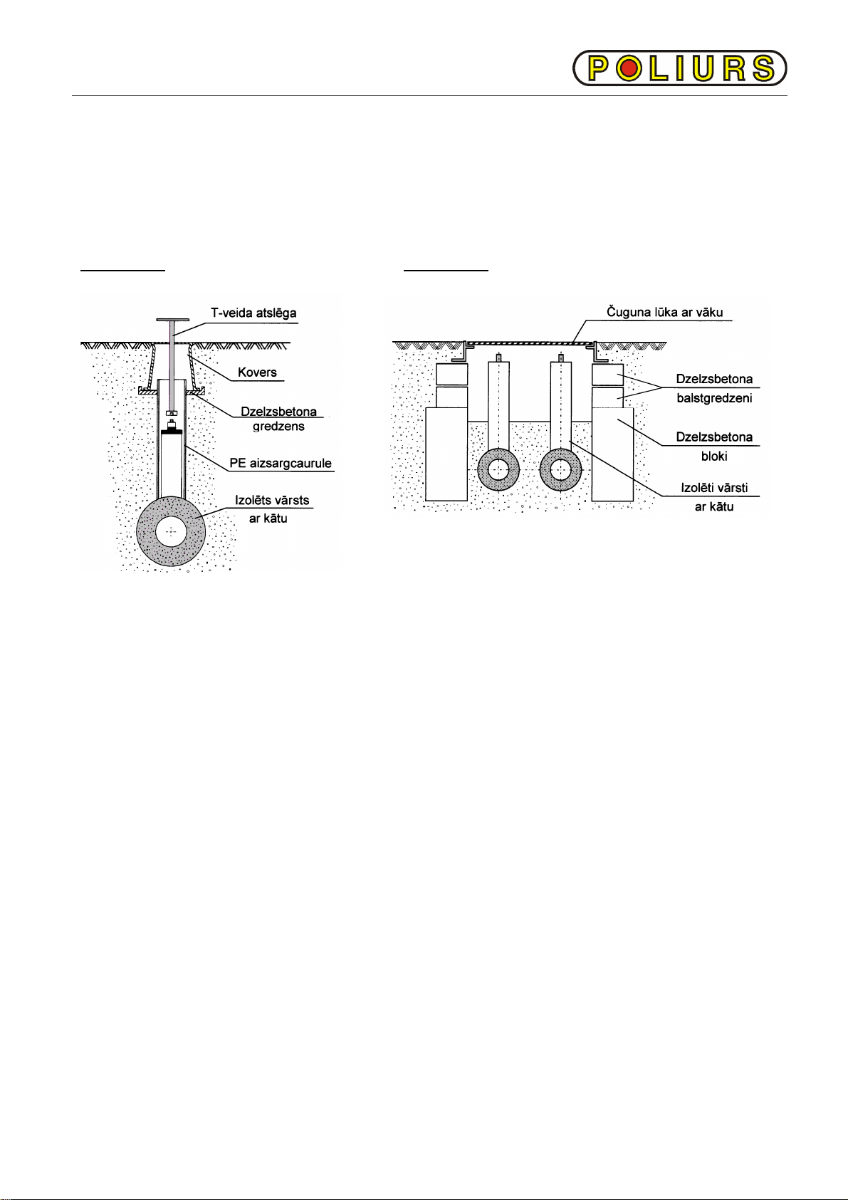
If main heating pipeline is deep enough,
then fitting branch can be placed with an
uplift and then trench will be deeper by H:
H = D + h,
If the depth of the main heating pipeline is
not deep enough, then T-piece should be
diverted to the bottom and piece trench
should be deeper then H.
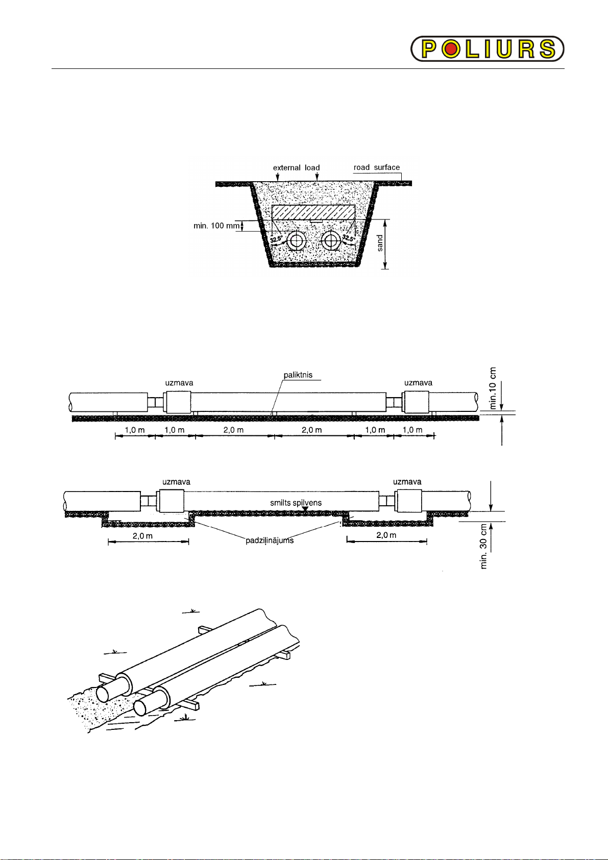
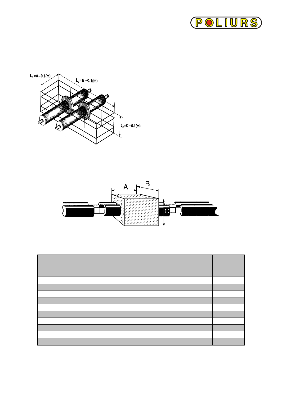
In places where compensation pillows are
placed, trench width should be increased,
depending on pillow amounts and location.
Trench widening shall comply with
compensation pillow length and thickness.
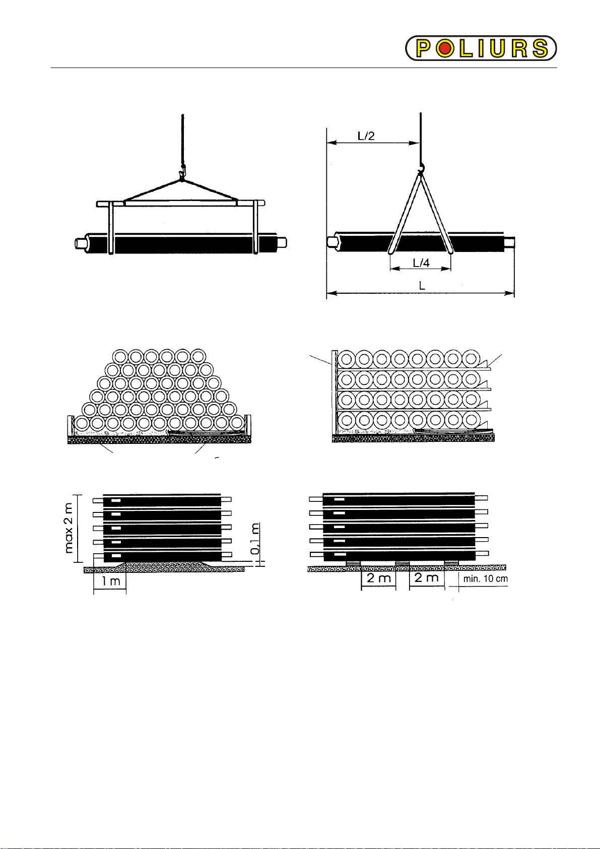
For above ground main pipeline is from
galvanized iron. During montage process
pipes are held together by sliding support.
Pipe is fixed to the sliding support with help
of clamp and non-metallic padding.
The welder should be certified according to the LVS EN 287 standard and according to
technology, which corresponds to LVS EN ISO 15607 demands.
Before steel pipe welding, on cover pipe should be put on cylindrical polyethylene (PE)
sleeves, which are use for connection montage.
To avoid damage of burning of the isolation material, ends of the pipe should be covered
or protected, for example with aluminum protectors. Protective materials should be
removed right after the welding is done and sleeve should get moved over the joining line.
After welding of the steel pipe check PE sleeve before placing it over the joining line.
Before montage, while performing montage and after, it is required so that pipes from
inside would be clean, dry and would not contain any foreign materials.
If after performing montage pipes require cleaning, then rinse them with water.
2.3.

HEATING MAIN MONTAGE INSTRUCTIONS CV4.04
3. CUTTING OF THE PREINSULATED PIPE
If it is required to shorten the length of the preinsulated pipe or is required to have fixed
length pieces, proceed accordingly:
1. On polyethylene casing mark
cutting place and from it on both
ends (distance of 150 to 180 mm)
clean section from insulation.
2. Cut the pipe in the marked place
along pipe circumference. With
sloped ring cut the casing
removable portion. Remove cut out
casing section.
3. Remove carefully the foam from
the middle section with the knife so
that wires stay untouched. Cut
alarm system wires. Clean all foam
insulation up to pipe casing. It is
unacceptable to have any sort of
damage done to the wires while
cutting, pulling, etc.
Cut main heating pipe. Cutting with gas torch, it is required to protect casing pipe and
polypropylene (PUR) isolation from over heating. Clean ends of the heating pipe from
foam leftovers. Cut pipe at the designated spot.
3.1.
cut line
cut
cleaning section
perpendicular
cut

HEATING MAIN MONTAGE INSTRUCTIONS CV4.04
4. FIXED ANCHOR MONTAGE
Industrially produced fixed anchor consists from 2-3 m long preinsulated pipes, where in
the middle, next to the work pipe, montages steel flap (cap, facing).
During montage procedure set up an
anchor block from reinforced
concrete around fixed support facing
(flange, top). Concrete anchor
strength secures montage steel
frame
The fixed anchor undergo the great
load during the pipeline lifetime,
therefore it is needed to install them
in the dense rammed soil.
For concrete placement use concrete kl. B25
Suggested anchor block sizes:
Steel
pipe
∅d, mm
Anchor size, m
AxBxC
Armature
diameter,
mm
Steel
pipe
∅d, mm
Anchor size, m
AxBxC
Armature
diameter,
mm
42
0,5 x 0,7 x 0,5
8 168
1,0 x 2,0 x 1,2
20
48
0,5 x 0,7 x 0,6
8 219
1,0 x 2,3 x 1,4
20
60
0,7 x 1,0 x 0,6
12 273
1,2 x 2,7 x 1,4
20
76
0,7 x 1,0 x 0,6
12 324
1,2 x 3,0 x 1,4
20
89
0,7 x 1,0 x 0,6
12
355 1,2 x 3,3 x 1,5
20
108
0,8 x 1,2 x 0,7
12
406 1,2 x 3,5 x 1,5
20
114
0,8 x 1,5 x 1,1
12
426 1,2 x 3,6 x 1,6 20
133
1,0 x 1,5 x 1,1
12
457 1,2 x 3,8 x 1,7 20
139
1,0 x 1,5 x 1,2
12
508 1,2 x 4,0 x 1,8 20
159
1,0 x 2,0 x 1,2
20
530 1,2 x 4,0 x 1,8 20
Pipeline operation could only begin after complete concrete solidification.
4.1.

HEATING MAIN MONTAGE INSTRUCTIONS CV4.04
5. PREINSULATED VALVE MONTAGE
Isolated spherical valves, isolated valves with air or drain release/ drainage are installed
into heat main the same as other fittings or straight pipe sections-after welding of the work
pipe and isolating joining places. Assembling (fitting) diagram must insure convenient
access to valve operating mechanism and safety against damages of the mechanism
while operating.
Version A. Version B.
Isolated valve montage is chosen from taking into account surface loads, engineering
works, municipal network location, etc.
Example A is used when surface loads are minimal (for example sidewalk, green territory),
example B - at greater surface loads, for example road or freeway.
While performing montage works valves must be in open position, in that way minimizing
probability of sealing damages.
From the ground surface valve is opened and closed using T-shaped key, which come in
the package. Reinforced concrete products and iron manhole covers „Poliurs” Ltd. does
not provide.
After assembly of the line and rinsing of the valve it is recommended to perform first
closing of the valve by turning T-shaped key in counterclockwise direction for 90°,
afterwards closing the valve by turning the key in opposite direction.
5.1.

HEATING MAIN MONTAGE INSTRUCTIONS CV4.04
6. HYDRAULIC TESTING
After the non-destructive testing of the welding; pipeline undergoes the hydraulic control,
recommended in several steps, with pressure that exceeds maximum service pressure 1.3
times but not less than 16 bar.
Testing should be made with costumer presence and supervision. About testing results
should be composed record (protocol).
Cold water should be used for hydraulic testing. The control pressure duration should take
at least 15 minutes.
Testing pressure can not be decreased for more than 5% from initial testing pressure.
During testing, montage stitch cannot show any moisture.
If the leak is found, then appropriate welding place should be cut out and repeatedly
welded. Hydraulic testing should be repeated.
Testing section should be disconnected from already working pipeline using seals.
The hydraulic testing should be carried out after welding of all connecting units, but before
montage of the sleeves.
6.1.

HEATING MAIN MONTAGE INSTRUCTIONS CV4.04
7. ALARM SYSTEM ASSEMBLING
If the casing pipe or the service pipe is damaged, there is a danger of humidity getting into
the heat insulation layer, which could destroy the heat insulation of the pipes, as well as
the untimely corrosion of the steel pipes.
The alarm system is installed in the preinsulated pipes and the joints, which enables to
recognize the humidity in the heat insulation layer.
Two copper not isolated wires are installed in the heat insulation layer of the pipe on
opposite sides of the pipe.
Place pipes in such way that alarm copper wires are located parallel to each other.
Free wire ends that are not isolated should be protected against any damage.
According to project scheme, alarm system montage should be performed before isolation
of the connection is pored between pipes. Montage of alarm system wires in unfavorable
weather is forbidden.
1. Begin montage of alarm wires from one
end, at the same time check resistance
in already connected segments.
Before connecting to the united alarm
circuit should check with megohmmeter
each pipes and joints isolation resistance
and resistance of the alarm system
wires. The resistance of the insulation
should be greater than 100 MΩ
2. Connect wires in the loop in such way
that they don’t come in contact with steel
pipe and check it for resistance. Results
should be registered in the montage
journal. Journal example is available in
the Addition Nr. 3.
7.1.

HEATING MAIN MONTAGE INSTRUCTIONS CV4.04
3. Continue checking wire resistance as
you connect more and more pipes into
the loop. Continue recording your
results in the journal.
4. In article 1 mentions insulation
resistance should be greater than 100
MΩ.
5. After checking for resistance connection of alarm system wires is performed in such
steps:
Cut straightened wire ends so that after
connection they are not hanging. Wire
ends of approximately 1-2 cm should be
cleaned carefully with sand paper.
Insert one end of the wire into the splicing
pliers and compress it with special tongs.
Insert and compress the other wire end.
Connection is brazes with the special
splicing sleeve.
Connect wires at the other end of the pipe
the same way.
For wires not to touch steel pipes they are
secured with special wire holder.
Place wire holders symmetrically and
attach them to steel pipe with duct tape.
7.2.

HEATING MAIN MONTAGE INSTRUCTIONS CV4.04
6. Insulation, wire loop resistance and wire
connection check should be performed
at every pipe connection. Record all
readings taken in the journal.
100 m long wire resistance should be
1,3 Ω±15%.
Assembled pipe network should not
have resistance of less than 200 kΩ.
7. At the end of the pipe network where
pipes are not going to be connected to
further connected pipes should be
connected in a loop and should be
secured to the insulation, eliminating
any chance of contact with steel pipe.
8. Control and measurement of alarm
system wires is possible by connecting
wires to the alarm box with the help of 3
lead connection cables. Cable main wire
should be connected to the steel pipe
with help of screw M8 and a wrench.
Alarm boxes are installed close to the
pipes entry in the house and/or heating
chamber.
It is advised to place shrinkable cap at
the end of the pipe to protect PUR
insulation and alarm wires. Also,
connect joining cable to alarm wires
underneath the cap.
Alarm system should be supervised at all time with acquired CWA 6000 systems (Sweden)
or other similar type equipment. Impulse reflection method is used for specific incident
place determination. Such equipment is available at „Poliurs” Ltd.
After alarm system montage and testing the supervisory alarm acceptance act should be
filled out (for act example see Addition Nr. 4). Keep in storage installation act and journals.
7.3.

HEATING MAIN MONTAGE INSTRUCTIONS CV4.04
8. INSTALLATION OF PREINSULATED PIPE JOINTS
After service pipe welding, alarm system montage and performed work inspection,
preinsulated pipe and/or joint connection montage are left these main stages:
- casing pipe end connection with sleeves;
- sleeve tightness and testing;
- Polyurethane (PUR) foam thermal insulation creation.
These stages may vary with different connection types.
Type 1 – simplest method for buried pipeline joining montage. Cover joint area with a PE
sleeve, cover the sleeve and casing pipe with heat-shrinkable tape, check sleeve tightness
(if it is required), pour in PUR mixed components.
Type 2 – technique, that insures double insulation for buried pipeline joint montage. Cover
joint area with heat-shrinkable PE sleeve, additionally secure ends with shrinkable tapes.
Insulate with pouring PUR components inside the sleeve or use PUR half casings.
Type 3 – use for pipeline connection above ground montage. Connection area cover with
aluminum foil and removable PE casing, pour in PUR components, remove casing and
seal insulation foam with one wide heat-shrinkable tape. Cover connection area with
casing - aluminum foil sheet.
Type 4 – this method is used in case joint needs to get fixed, PE casing is not placed on
before welding, or free space for PE casing is not long enough to move aside it from the
connection. It is similar to Type 3, only for below ground pipelines do not use galvanized
casing.
While performing montage connection it is required to take into account general safety
requirements. It is required to work with appropriate work instruments, in proper work
clothes, with protective eye wear and appropriate work gloves.
Components "A" and "B" until they are used should be kept in protected from sunlight
space at the temperature +20°±5°C. It is advised to use electronic mixer for mixing the
components together. If PUR component come in direct contact with unprotected areas of
skin then that area needs to be immediately rinsed with warm water (please view attached
safety procedures).
If joining montage is made during bad weather conditions, then work place should be
covered with water proof cover.
Joining montage is not recommended at the temperatures lower than +5°C. In special
cases, if the surrounding temperature is lover than critical temperature, it is possible with
use of technical methods to insure proper foam forming, for example:
- supply hot water through pipeline;
- preheat installation area with electric heaters or soft gas flame;
- store for a long time components in room temperature and act fast not letting it to
cool down until filling in moment.
In case of unfavorable weather it is advised to try the foaming of the components before
using them to see how well and how fast the foaming is and if it will do the job of filling of
the needed diameter sleeve.
8.1.

HEATING MAIN MONTAGE INSTRUCTIONS CV4.04
8.1. CONNECTION MONTAGE. TYPE 1.
Necessary materials:
- PE sleeve,
- heat-shrinkable tape - 2 pieces,
- seal patch - 2 pieces;
- PUR foam components "A" and "B";
- round (FOPS) patch - 2 pieces;
- cork for air release -1 pieces;
- materials for alarm system installation, if planned.
Montage equipment and instruments:
- gas torch;
- soldering burner (for alarm wires);
- measuring bowl – 2 pieces;
- bowl for mixing and filling of components;
- mixer;
- sand paper (rough on fabric base);
- degreasing liquid (for example: acetone);
- brush or rag;
- goggles, gloves;
- hand drilling machine;
- drills: Ø25 mm, Ø3 mm;
- megahommeter for alarm testing.
If the joint seal check is scheduled, then additional tools are needed:
- tightness control device (manometer);
- Air-pump (tire pump can be used).
Montage sequence:
1. If pipe end insulation is damaged, cut damaged part. Check and connect alarm wires.
2. PE casing that is located on one of the preinsulated pipe, symmetrically push onto the
connection area.
3. Drill a hole in PE casing at the distance of
Ø25mm ~50 mm from end of insulation.
4. Drill another hole in PE casing in 3 mm
diameter
(for air release) at the distance of
~50 mm from the other side of
end
insulation.
8.1.1.

HEATING MAIN MONTAGE INSTRUCTIONS CV4.04
5. Make sure that sleeve and insulation
ends are dry, clean and not greasy. If
necessary, dry, clean and remove all
grease at the distance of B+50+50 mm
(B – length of heat-shrinkable tape) and
polish with sand paper. Clean the rest
of the polyethylene particles.
6. With every casing pipe diameter Dcut heat-shrinking tape with length Laccording to
the table:
D,mm
90 110
125
140
160
180
200
225
250
280
315
355
400
450
500
560
630
L, m 0,39
0,45
0,50
0,55
0,61
0,68
0,75
0,84
0,92
1,02
1,14
1,27
1,43
1,59
1,77
1,97
2,20
At one end of the tape cut sloped
corners.
7. Using propane-butane flame, preheat
up to 60°C area that was previously
treated with sand paper.
8. Removing protective film from the
heat-shrinkable tape place cut side on
the sleeve end in a way that 40% from
tape width would be located on the
preinsulated pipe and 60% would be
on the sleeve.
8.1.2

HEATING MAIN MONTAGE INSTRUCTIONS CV4.04
If "DualSeal" heat-shrinkable tape is
used, then it should be placed
according to the marking on it. Place
tape at the connection area exactly at
the connection joint, so the distance
covered would be the same on the pipe
and on the sleeve.
Heat up tape end with a gas torch for
about 1-3 seconds and press against
PE surface.
Without pulling, place tape along
circumference of the pipe and at the
same time removing protective film.
Heat up the end of the tape for about 1-
3 sec. and press it against the surface
at the distance of ~50 mm on to the
tape.
9. Place patch on the tape stitch (with
crossings on the surface). Heat it up
with weak flame and press hard on it,
starting from one end and moving to
the opposite side.
8.1.3.
Marking

HEATING MAIN MONTAGE INSTRUCTIONS CV4.04
10. Begin shrinking of the tape from the
middle towards one end, towards sleeve
end. Heating up with weak flame along
circumference of the tape, shrinking one
half of the tape. Let it cool down for
approximately 2-3 minutes. At this time
place tape at the other end of the sleeve,
and performing steps 7-10.
"DualSeal" heat-shrinkable tape does not
need any time for cooling.
Next, heat other side of the tape that is
located on the preinsulated pipe.
That way there won’t be any air trapped
underneath the tape.
Melt glue is an indication when tape
temperature is sufficient.
If "Dual Seal" heat-shrinkable tape is
used then heat it up until green indication
vanishes.
It is recommended to perform checks,
push tape with finger in such way, that
wrinkles form, that after heating up
vanish, forming smooth surface.
Perform same technique in shrinking
tape at the other end of the sleeve.
Tape shrinking is performed acceptable,
if after correct pipe surface preparation
and heating of the tape, it is pressed tight
around joint circumference; glue got
uniformly squeezed out from the tape.
No bubble can be seen nor not enough
heated areas.
8.1.4.

HEATING MAIN MONTAGE INSTRUCTIONS CV4.04
Fill sleeve with PUR foam components
only after cooling of the sleeve down to
the surrounding temperature.
11. In separate containers pour components “A" and "B" in quantities that are specified in
Addition Nr 5 tables.
Pour component "A" and then component "B" in one container and for not longer than
15 minutes mix rapidly the component.
Within 30 seconds pour mixed component in the drilled hole, Ø 25 mm in diameter.
If components "A" and "B" are in separate containers and are for only one connection,
then pour component "B" into the container with component "A", mix rapidly and pour
into the drilled hole with diameter of Ø 25 mm.
12. Close drilled hole with PE cork.
13. After PUR foam hardening (not earlier
than in 2,5 hours) cut cork top part,
clean PE sleeve surface from dust and
foam remains around drilled holes ( ~70
mm in radius). Heat up to 60°C using
weak flame area around cork for the
FOPS patch.
14. Heat sticky side of the patch for about 1-
3 sec. and press it against the cork.
Heat the patch with weak flame until
green indicator on the patch is gone.
It is not allowable for glued patch to
have any air entrapped underneath it or
have corners bent up. Around the patch
side wide region of glue should be
seen.
8.1.5.
Table of contents
Popular Heating System manuals by other brands

aoyue
aoyue Int883 instruction manual

Girafus
Girafus V-15 manual

OSTBERG
OSTBERG HERU K Series Assembly and installation instructions

Ducasa
Ducasa Easy Control instruction manual

Hitachi
Hitachi UTOPIA R32 Series Installation & operation manual

Ducasa
Ducasa AVANT-DGi+ 350 Operating and installation instructions

Carrier
Carrier Z6 user manual

Toyotomi
Toyotomi OM-22 Type A Installation and operation instructions

Iloxair
Iloxair ILOX 129 Installation, operation and maintenance guide

SIC
SIC CFR micro E Series Installation, use and maintenance manual

Könighaus
Könighaus E Series Original instruction manual

Myson
Myson 7-4 Installation & maintenance manual