Introduction
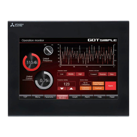
Thank you for purchasing the Mitsubishi Graphic Operation Terminal.
Before using the equipment, please read this manual carefully to develop full familiarity with the functions and
performance of the graphic operation terminal you have purchased, so as to ensure correct use.
Please forward a copy of this manual to the end user.
Table of Contents
1. OVERVIEW 1-1
1.1 Features............................................................................................................................................................ 1- 1
2. SYSTEM CONFIGURATION 2-1 to 2-2
2.1 Overall Configuration ........................................................................................................................................ 2- 1
2.2 Applicable System ............................................................................................................................................ 2- 2
3. SPECIFICATIONS 3-1 to 3-24
3.1 General Specification........................................................................................................................................ 3- 1
3.2 Performance Specifications .............................................................................................................................. 3- 2
3.3 Temperature/Digital Conversion Characteristics............................................................................................... 3- 4
3.4 Maximum Transmission Distance over the CC-Link System ............................................................................ 3- 4
3.5 Data Link Processing Time. .............................................................................................................................. 3- 5
3.6 Twisted Cable Specifications ............................................................................................................................ 3- 6
3.7 Function List...................................................................................................................................................... 3- 7
3.8 I/O Signals in Respect to the Master Module.................................................................................................... 3- 8
3.8.1 I/O signal list .......................................................................................................................................... 3- 8
3.8.2 I/O signal functions ................................................................................................................................ 3-11
3.8.3 Wire breakage detection........................................................................................................................ 3-16
3.8.4 Conversion enable/disable designation ................................................................................................. 3-17
3.8.5 Sampling processing/travel average processing designation................................................................ 3-18
3.8.6 Thermocouple type selection................................................................................................................. 3-20
3.8.7 Pt100 cold junction compensation enable/disable designation ............................................................. 3-21
3.9 Remote Register ............................................................................................................................................... 3-22
3.9.1 Remote register assignment.................................................................................................................. 3-22
3.9.2 High and low limit settings ..................................................................................................................... 3-23
3.9.3 Detected temperature value .................................................................................................................. 3-24
3.9.4 Scaling value ......................................................................................................................................... 3-24
4. SETTING AND PROCEDURE BEFORE OPERATION 4-1 to 4-10
4.1 Procedure before Operation ............................................................................................................................. 4- 1
4.2 Handling Precautions........................................................................................................................................ 4- 2
4.3 Part Identification and Setting ........................................................................................................................... 4- 3
4.4 Error Compensation by the Offset Value/Gain Value Setting ........................................................................... 4- 5
4.4.1 Initial settings for error compensation.................................................................................................... 4- 6
4.4.2 Error compensation procedure .............................................................................................................. 4- 7
4.5 Station Number Setting..................................................................................................................................... 4- 8
4.6 Orientation of Module Installation ..................................................................................................................... 4- 8
4.7 Wiring................................................................................................................................................................ 4- 9
4.7.1 Wiring example with CC-Link modules .................................................................................................. 4- 9
4.7.2 Precautions when wiring to a thermocouple .......................................................................................... 4-10
4.7.3 Wiring example with thermocouple........................................................................................................ 4-10
Downloaded from ManualsNet.com search engine


