
documentation [https://www.microchip.com/wwwproducts/en/ATmega32u4].
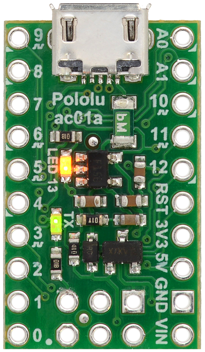
Printed on the A* circuit board are indicators that you can use to quickly identify each pin’s capabilities:
a triangle next to the pin means it can be used as an analog input, and a square wave symbol under
the pin number means it can be used as a PWM output.
LEDs
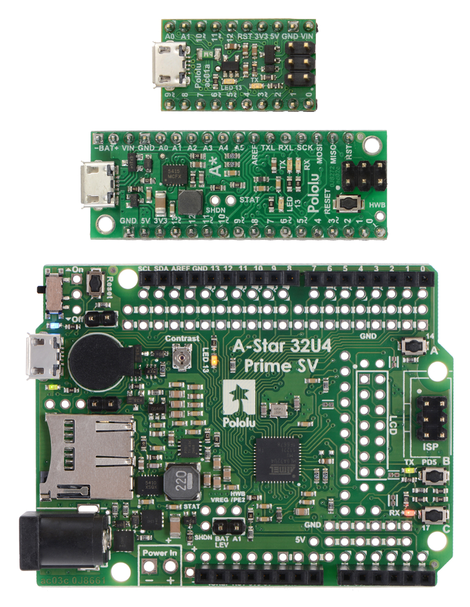
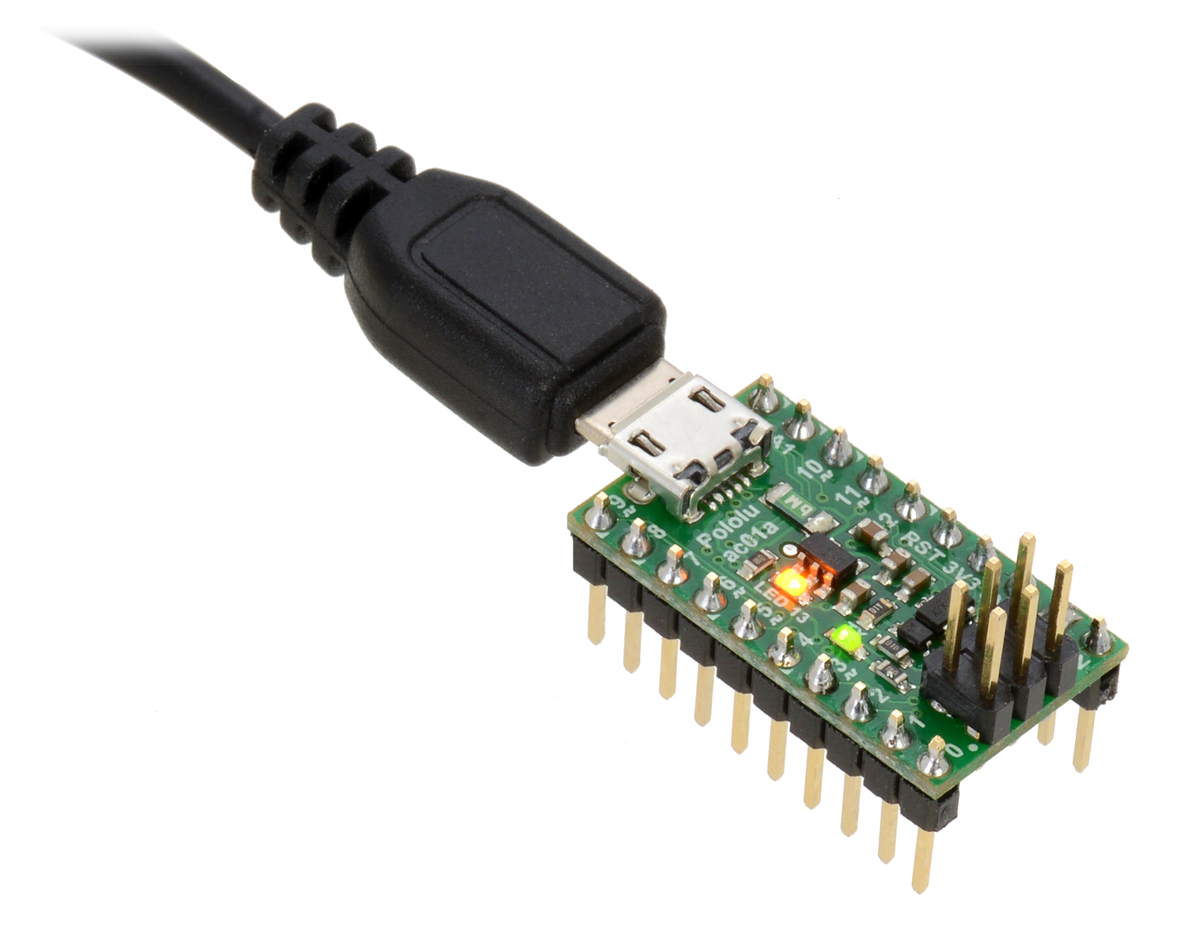
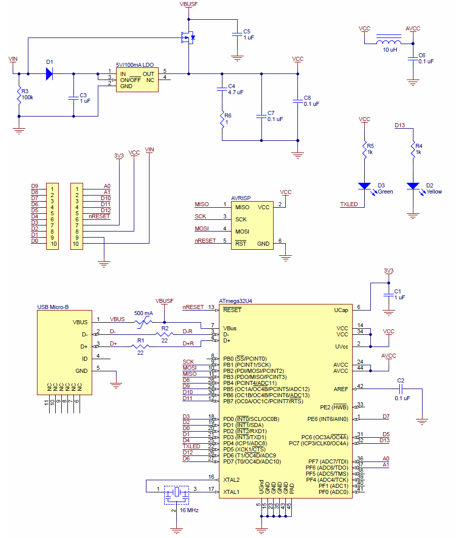
The A-Star 32U4 Micro has two indicator LEDs.
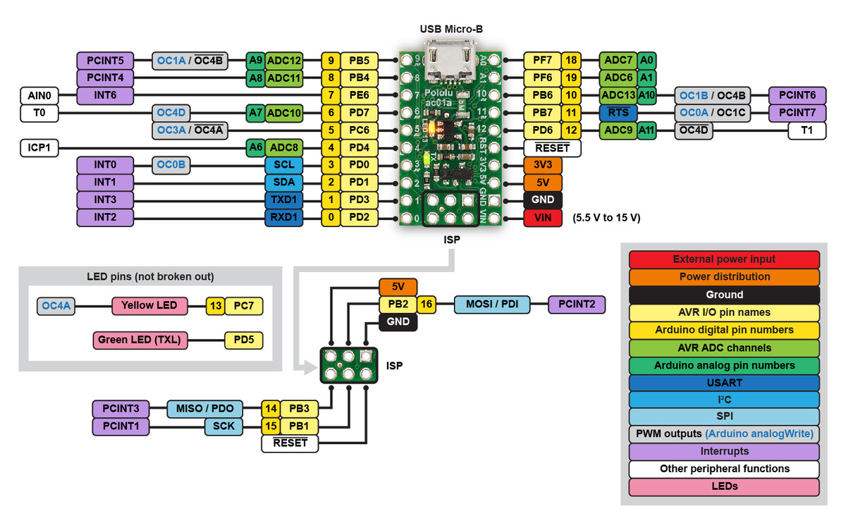
The yellow LED is connected to Arduino pin 13, or PC7. You can drive this pin high in a user program
to turn this LED on. The A-Star 32U4 Bootloader [https://www.pololu.com/docs/0 61/9] fades this LED on
and off while it is waiting for a sketch to be loaded.
The green LED is connected to PD5 and lights when the pin is driven low. While the board is running
the A-Star 32U4 Bootloader or a program compiled in the Arduino environment, it will flash this LED
when it is transmitting data via the USB connection.
Connectors
The A-Star 32U4 includes a USB Micro-B connector that can be used to connect to a computer’s
USB port via a USB A to Micro-B cable [https://www.pololu.com/product/2072] (not included). The USB
connection can be used to transmit and receive data from the computer, and a preloaded USB
bootloader makes it possible to program the board over USB. The USB connection can also provide
power to the A-Star.
The board also has a 6-pin ISP header that allows it to be programmed with an external programmer,
such as our USB AVR programmer v2.1 [https://www.pololu.com/product/3172]. Pin 1 of the header is
indicated with a small white dot and has an octagonal shape. Three of the pins on this header can
be used as an SPI interface or as general-purpose digital I/O, as shown in the pinout diagram. In
the Arduino environment, you can refer to these three pins using either their pin numbers or the
names of their SPI functions (which are defined as aliases); for example, digitalRead(15) and
digitalRead(SCK) are equivalent.
Power
The A-Star 32U4 Micro can either be powered directly from the USB 5 V supply or from a separate
source on the VIN pin. The board features a power selection circuit that allows both USB and VIN to
be connected at the same time; if this is done, the A-Star will draw power from VIN.
USB power input: The A-Star can be powered from the USB 5 V bus voltage (VBUS) if it is connected
to a USB cable. It will draw power from USB only if VIN is disconnected. A resettable PTC fuse on
VBUS makes it less likely for the A-Star (and the connected computer or other device) to be damaged
Pololu A-Star 32U4 User’s Guide © 2001–2018 Pololu Corporation
3. A-Star 32U4 Micro Page 8 of 59


