Polon-Alfa POLON 4000 Series Manual

POLON 4000
INTERACTIVE FIRE DETECTION AND ALARM SYSTEM
ROP-4001M & ROP-4001MH
FIRE MANUAL CALL POINTS
Installation and Maintenance Manual
IK-E325-001GB
IIC Edition

2 IK-E325-001GB
The ROP-4001M and ROP-4001M manual call points, covered by the present manual, complies with
the requirements of the following European Union directives:
CPD 89/106/EWG on electric construction materials;
EMC 2004/108/WE on electromagnetic compatibility.
The ROP-4001M and ROP-4001M manual call points have been attested with the EC-Certificate of
Conformity No. 1438/CPD/0090 issued by the Scientific and Research Centre for Fire Protection
(CNBOP) Józefów, Poland, a EU notified authority No. 1438, confirming its compliance with the
requirements of the PN-EN 54-11:2004 standard.
The certificate may be downloaded from www.polon-alfa.pl web site.
The ROP-4001M and ROP-4001M call points have been approved by the CNBOP with the Allowance
Certificate No. 0345/2008.
1438
Polon-Alfa Spółka z ograniczoną odpowiedzialnością Sp. k.
155, Glinki Street, PL 85-861 Bydgoszcz, POLAND
07
1438/CPD/0090
EN 54-11
ROP-4001M & ROP-4001MH manual all points (addressable, B type)
Application – fire safety
Technical data - IK- E325-001GB manual
Read the manual carefully before assembling and operation. Any nonconformity with the instructions
contained in the manual may be harmful or may cause a violation of the law in force.
POLON-ALFA bears no responsibility for any damage resulting from any usage inconsistent with the
manual.
The waste product, unsuitable for further use, shall be passed to
a waste electric and electronic equipment collection point.
NOTE: The manufacturer reserves a right to change specifications of the products at any time
without a prior notice.

IK-E325-001GB 3
1 PURPOSE
The ROP-4001M and ROP-4001M manual call points are designated for operation in addressable
loops of the POLON 4000 system detecting lines. They are addressable devices installed in order to
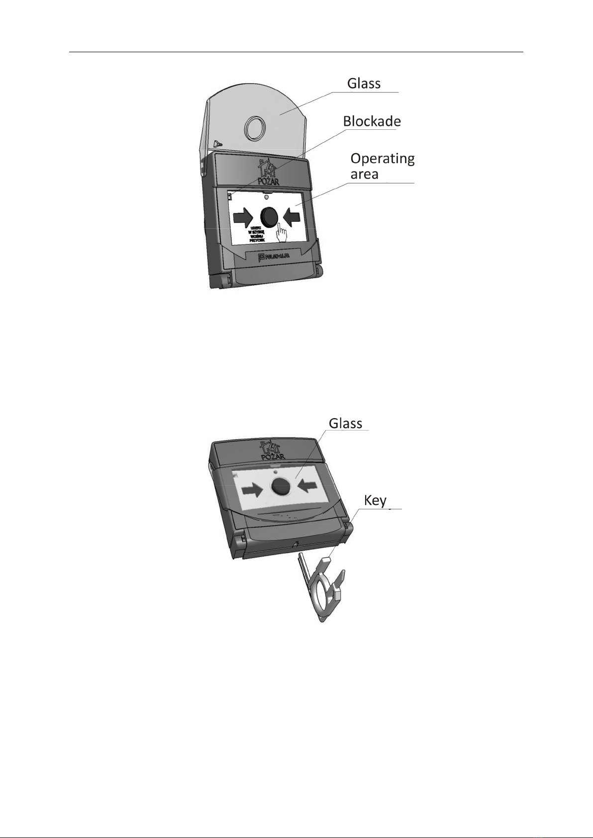
transfer information about a noticed fire by their manual actuation.
The ROP-4001M manual call point in the standard execution is intended for indoor installation.
The ROP-4001M manual call point (with a higher ingress protection level) is intended for outdoor
installation.
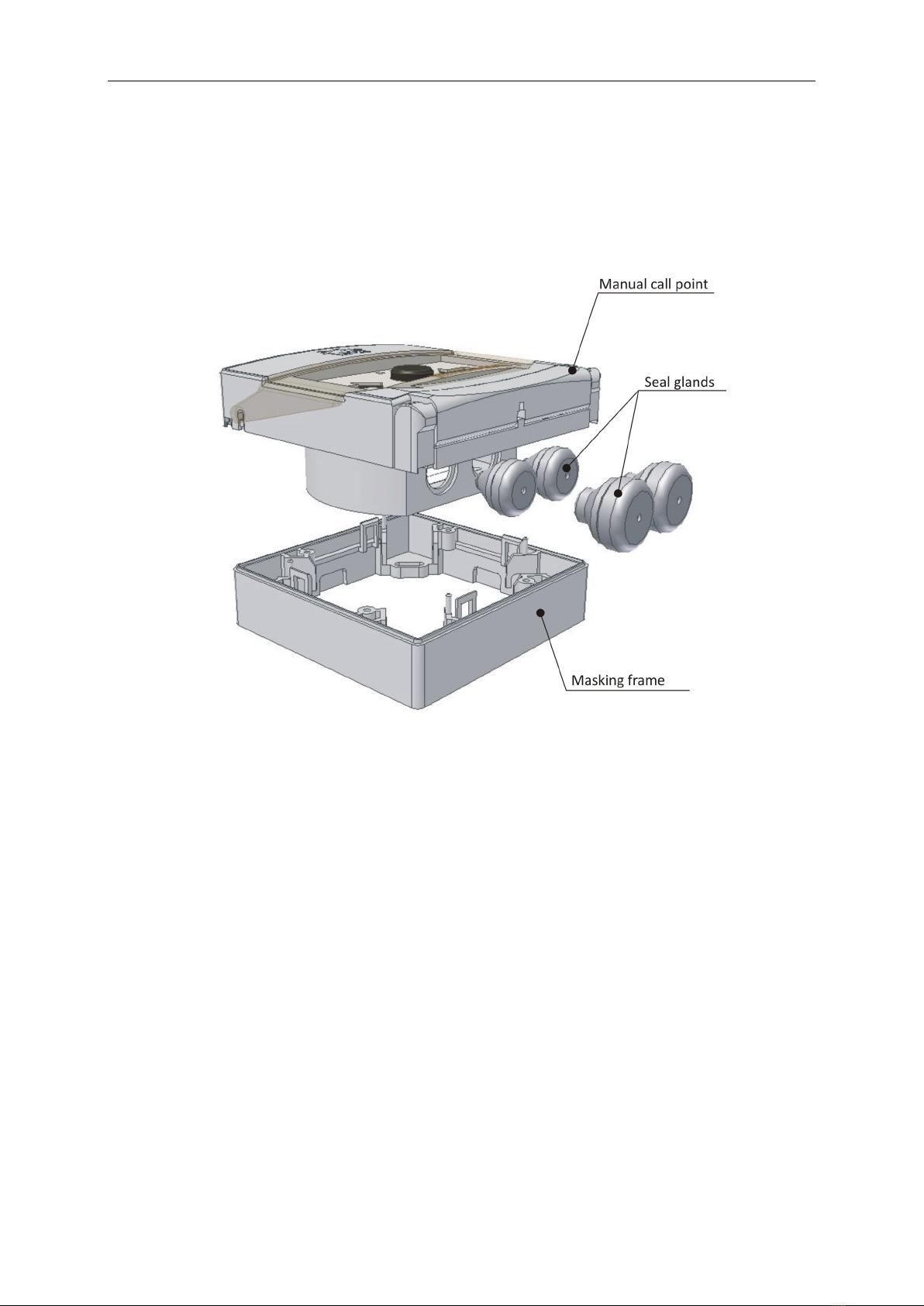
Both versions are suitable for semi-flush (in wall plaster) and surface (on wall plaster) mounting
installation – the basic version is the first one, the semi-flush type. A special auxiliary RM-60-R
masking frame is applied for surface mounting; it is not a part of the standard equipment and should
be ordered separately.
2 TECHNICAL SPECIFICATIONS
Call point type B, acc. to PN-EN 54-11:2004
Operation voltage (from detection line) 16.5 V … 24.6 V
Max. current draw in quiescent mode < 140 µA
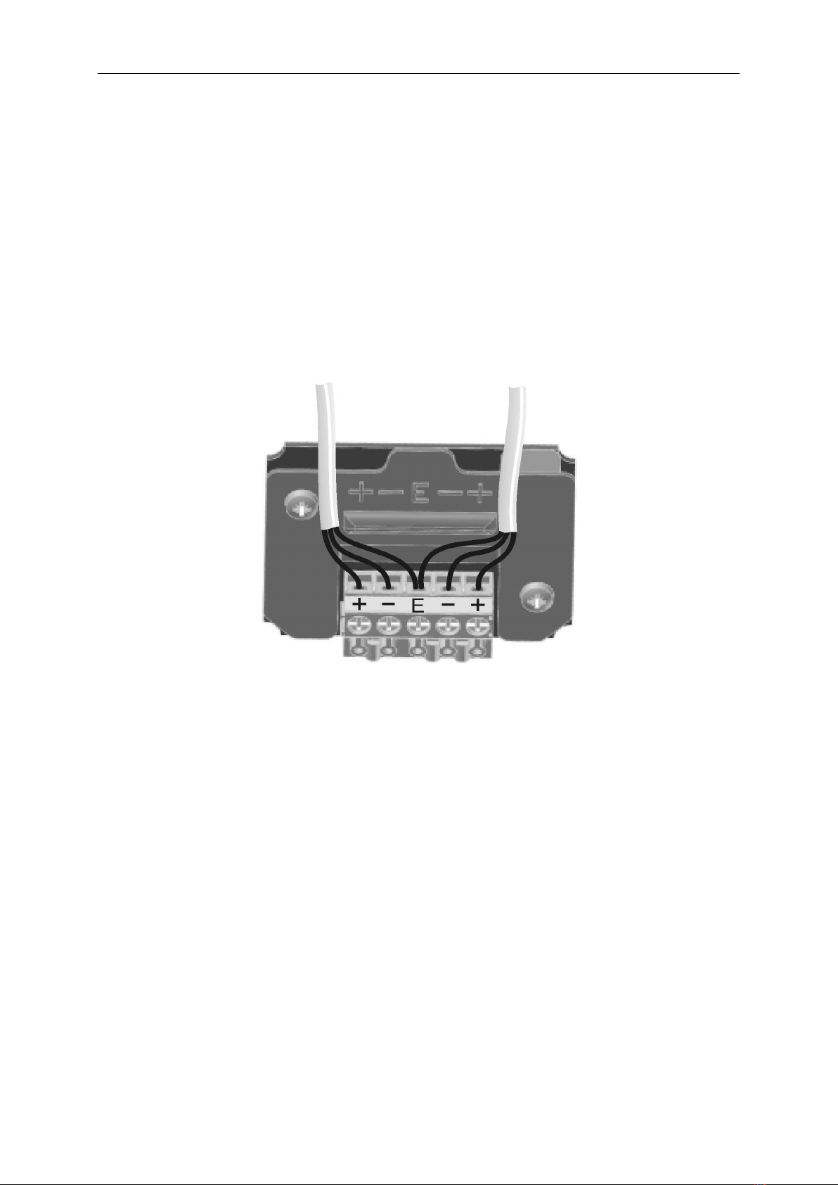
Allowable cable wire diameter 0.8…1.2 mm
Address coding range 1 ÷ 127
Ingress protection:
ROP-4001M IP 30
ROP-4001M IP 55
Operating temperature range:
ROP-4001M from -25 °C to +55 °C
ROP-4001M from -40 °C to +70 °C
Allowable relative humidity: up to 95 % at 40 °C
Dimensions 102.5 x 98 x 45.5 mm
Mass:
ROP-4001 < 220 g
ROP-4001 < 260 g
Case colour red
3 SAFETY CONDITIONS
3.1 Repairs and maintenan e
Any maintenance works or periodic inspections shall be executed by a skilled personnel employed by
companies authorised and trained by POLON-ALFA.
Any repairs must be carried out by the manufacturer. POLON-ALFA bears no responsibility for the
operation of any apparatus being serviced and repaired by an unauthorised personnel.
3.2 Anti-dusting eye prote tion
It is obligatory to use protective anti-dusting glasses and masks during installation works that
produce high amount of dust, such as hole drilling in walls.
Any electric tools shall be used strictly obeying the safety rules stated in the manufacturer instruction
manuals.

4 IK-E325-001GB
4 DESIGN DESCRIPTIONS
The manual call point consists of a body and a base connected with a hinge.
The manual call point body contains its main parts: a printed circuit board with an electronic circuit,
micro-switch and connector to install detecting line wires. A two-colour illuminating diode, indicating
the alarm or fault mode, is located in the device upper part behind the glass.
Fig. 1. Manual call point general view
The manual call point of ingress protection higher level is mounted on the wall plaster (surface
mounting), utilising the RM-60-R masking frame. For wire sealing, the FET 3-5 sealing glands are
attached, which are applicable for wires of the external diameter of 3 to 5 mm. In case bigger cables
are used (of the diameter from 5 to 7 mm), the FET 5-7 seal glands should be ordered separately. In
order to apply the FET 5-7 seal glands it is necessary to increase the diameter of the openings drilled
in the body up to 16.5 mm.
5 PRINCIPLE OF OPERATION
The manual call point actuation – initiation of an alarm – is carried out by hitting a plastic cover
(which bends aside) and pressing the push button then.
The colour of arrows changes from black to yellow and the call point transmits information about the
button pressing to the control panel which send to the call point a signal actuating the LED indicator.
Red flashes indicate the manual call point actuation.

IK-E325-001GB 5
Fig. 2 Manual call point with cover bent aside
In order to reset the manual call point alarm state it is necessary to press the cover down towards
the body as shown in Fig. 3 and insert the key (T end) from the bottom until the arrows in the
operation area change their colour from yellow to black. After the key removal, the cover is blocked
again in its normal position.
Fig. 3 Alarm mode reset
Note:
If the cover is not hit but pulled aside (inconsistently with the instruction placed on the call point)
and the push button is not pressed (the call point alarm mode is not activated), it is necessary to
press the cover down towards the operation area and block it in this position inserting the key from
the bottom of the call point.

6 IK-E325-001GB
6 INSTALLATION
6.1. Installation and mounting
The call points, depending on their type, are designed to be installed either indoors or outdoors, in
easily accessible visible places, preferably close to transport routes, 1200 -1600 mm above the floor
in accordance with PKN-CEN/TS 54-14:2006 standard p. 6.5.4 .
It is advised to determine the installation hole spacing (diagonally – see Fig. 4 and Fig. 5) utilizing a
pattern, not the device itself or its masking frame.
The call point is fastened to a flat surface using two Ø6 anchor expansion bolts and cylindrical head
screws that are delivered together with the call point.
In case of semi-flush mounting, a hole of 80 mm diameter (typical for electric installation box) and 22
mm depth should be drilled in the wall.
For the call point on surface fastening, the RM-60R masking frame is applicable.
Since a considerable strength is needed to open the cover, it is advised to strengthen gypsum-carton
boards on which the manual call point is mounted.
Fig. 4. Manual call point dimensions and fastening holes
Fig. 5. RM-60-R masking frame dimensions and fastening holes

IK-E325-001GB 7
6.2 Wire arrangement
Alarm installation wires shall be led in accordance with the low-voltage (below 42 V) installation
obligatory rules and connected to the contacts placed on the printed board of the call point.
In case of manual call points installed outdoor (hermetic), the wires must be led from the bottom of
call point trough seal glands.
For the manual call point easy connection some wire reserve shall be left of the length as follows:
- ca. 40 cm in case of surface mounting installation,
- ca. 30 cm in case of semi-flush installation.
6.3 Wire onne tion
Loop-shaped detecting line wires are connected to “+” and “-“ contacts, separately for an input and
an output. In case of screened wires, the screens are joined together and connected to the contact
on the board marked as “E”. The way of connection settling is shown in Fig. 6.
Fig. 6 Detecting line connection diagram
To access the printed circuit board where the connector is located, it is necessary to push two keys
(with flat ends) from the side what will bend the manual call point casing aside.

8 IK-E325-001GB
Fig. 7 Manual call point opening method
Fig. 8 Manual call point after opening
6.4 Plasti over repla ement
In case the cover replacement is needed, it is necessary to bend the casing aside (see Fig. 7), pull the
cover out and take the spring out. Then the spring should be placed on a hinge of a new cover as it is
shown in Fig. 9.

IK-E325-001GB 9
Fig. 9 Cover spring assembly
Then it is needed to insert the cover into the casing rails and hook the spring on a ledge in the call
point casing (see Fig. 10).
Fig. 10 Spring fastening to casing
A set of 3 spare plastic covers is described as SZ-60.

10 IK-E325-001GB
7 SERVICE AND MAINTENANCE
The manual call point unfailing operation depends on ensuring proper operation conditions,
appropriate assembly execution and systematic periodical inspections. From time to time the call
point casing should be checked (mechanical condition) and cleaned.
The periodical inspections should be carried out at least once a year by a suitably trained
maintenance technician or an authorized person. Such an inspection consists in the manual call point
activation and checking whether an alarm signal is passed to the control panel.
Properly operating call points, periodically inspected and tested do not require any additional
maintenance.
8 PACKING, STORAGE NAD TRANSPORTATION
The manual call points are packed in bulk containers. An installation and maintenance manual is
attached to the device. The call points in a factory packaging can be carried in closed boxes in
normal conditions with land or sea transport means. The devices should be protected against strong
shakes and ambient temperature below – 40
0
C and above +70
0
C . They should be stored in closed
premises that are free of corrosive gases or vapours, at ambient temperature from +5
0
C to +40
0
C
and relative humidity between 40% and 80% away from heating devices. The storage period should
not exceed 24 months.
IK-E325-001GB/09.2010/05.2012
Other manuals for POLON 4000 Series
5
This manual suits for next models
2
Table of contents
Other Polon-Alfa Security System manuals