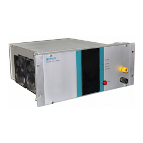
Ponovo PAV15000 User manual

PAV15000 Power Amplifier User Manual
1
PONOVO POWER CO., LTD
No. 139 Jinghai Third Road, BDA, Beijing, China, 100176
Office TEL. +86 (10) 59089666
Website www.relaytest.com / www.ponovo.com.cn
PAV15000
POWER AMPLIFIER USER MANUAL
VERSION: PAV15000-AE-1.00
DATE: MAY, 2019
This manual is the publication of PONOVO POWER CO.,LTD. Any form of copy should
obtain the consent of it.
The manual represents the technology status at publication time. The product information,
directions and all technical specifications do not have contract binding. The company
subjects to changing the technical and configuration information without notice. The
company is not responsible for possible errors occurred in the manual.

PAV15000 Power Amplifier User Manual
2
Content
1. Safety Precautions................................................................................................3
2. General Description..............................................................................................7
3. Main Technical Specifications...............................................................................8
3.1 Power Supply.........................................................................................8
3.2 Environment Conditions.........................................................................8
3.3 Dimension and Weight...........................................................................8
3.4 Technical Specifications.........................................................................9
4. Functions and Features...................................................................................... 11
5. Unit Function and Wiring Connection.................................................................12
5.1 Main power ...................................................................................................12
5.2 Amplifier ........................................................................................................14
5.3 Monitor unit...................................................................................................17
6. Amplifier Operation.............................................................................................19
6.1 Power On......................................................................................................19
6.2 Power off.......................................................................................................20
6.3 Pause for emergency....................................................................................20
7. Monitoring and Amplifier Module Operation.......................................................21
7.1 Monitoring operation.....................................................................................21
7.2 Power Module Operation..............................................................................25
PAV15000 Power Amplifier User Manual
3
1. Safety Precautions
Carefully read the user manual before operation.
1. Check carefully all buttons are positioned correctly before startup.
1) Pause button in correct position in pressed state.
2) ON/OFF in OFF state.
2. Main supply capacity should meet the requirement; otherwise it will affect output power
of amplifier during high current output.
3. Handle the amplifier with great care and follow the symbols on the package: fragile,
handle with care, top (an arrow pointing up), keep dry and protect from shaking.
4. Never operate live signal and load wires with voltage or current output to protect the
safety of equipment and personnel.
5. In case the power outlet for powering up the amplifier does not have protective
ground customer must connect the ground socket to the protective ground at the
test site
6. The voltage output of over 36V is considered as dangerous and care must be
taken.
7. Please close and lock the back door when the wiring connection is confirmed
correctly.

PAV15000 Power Amplifier User Manual
4
For Your Safety Please Note
This symbol indicates potential hazards by electrical voltages/currents caused by, for
example, wrong connections, short-circuits, technically inadequate or faulty equipment or by
disregarding the safety notes of the following sections.
Use Proper Power Cord
Only the power cord designed for the instrument and authorized by local country could be
used.
Ground The Instrument
The instrument is grounded through the Protective Earth lead of the power cord. To avoid
electric shock, it is essential to connect the earth terminal of power cord to the Protective
Earth terminal before any inputs or outputs.
Observe All Terminal Ratings
To avoid fire or shock hazard, observe all ratings and markers on the instrument and check
your manual for more information about ratings before connecting.
Do not Assemble/Disassemble the Instrument without
Authorization
The instrument should be assembled and or disassembled by professional engineers; users
are not allowed to perform related operations except for some possible replacements in this
manual.
Do not Move or Maintain the Instrument When it is Powered On
To avoid personnel injuries, any position adjustment, maintenance or parts replacement are
forbidden when instrument is on.
Use Proper Fuse
Please use the specified fuses.

PAV15000 Power Amplifier User Manual
5
Do Not Operate With Suspected Failures
If you suspect damage occurs to the instrument, have it inspected by qualified service
personnel before further operations. Any maintenance, adjustment or replacement
especially to circuits or accessories must be performed by authorized personnel.
Keep Well Ventilation
Inadequate ventilation may cause increasing of temperature or damages to the device. So
please keep well ventilated and inspect the intake and fan regularly.
Do Not Operate in Wet Conditions
In order to avoid short circuiting to the interior of the device or electric shock, please do not
operate in a humid environment.
Do Not Operate in an Explosive Atmosphere
In order to avoid damages to the device or personal injuries, it is important to operate the
device away from an explosive atmosphere.
Keep Product Surfaces Clean and Dry
To avoid the influence of dust and/or moisture in air, please keep the surface of device clean
and dry.
Operate the Instrument in a Suitable Environment
The best condition for optimal measurement is: 5 ℃to 40℃; less than 2 ℃/hour changing,
20% to 80% RH and the instrument should not be placed towards the air outlet.
Electrostatic Prevention
Operate in an electrostatic discharge protective area environment to avoid damages
induced by static discharges. Always ground both the internal and external conductors of the

PAV15000 Power Amplifier User Manual
6
cable to release static before connecting.
Proper Use of Solvent
Please use the solvent in compliance with instructions specified in its supplier. If necessary,
wear protective clothing, gloves and glasses to avoid any injuries.
Handling Safety
Please handle with care during transporting to avoid damages to surface, panel and parts
resulting from the falling from your hand.
NOTE: This equipment has been tested and found to comply with the limits for a Class A
digital device, pursuant to Part 15 of the FCC Rules. These limits are designed to provide
reasonable protection against harmful interference when the equipment is operated in a
commercial environment. This equipment generates, uses, and can radiate radio frequency
energy and, if not installed and used in accordance with the instruction manual, may cause
harmful interference to radio communications. Operation of this equipment in a residential
area is likely to cause harmful interference in which case the user will be required to correct
the interference at his own expense.

7
PAV15000 Power Amplifier User Manual
2. General Description
PAV15000 is the four-quadrant amplifier with high power applied in the semi-physical
simulation power platform to analyzer the sensitive load, the equipment power adaptability,
and the electric vehicle, etc and provide the technical support and service on the power
quality.
PAV15000 is designed on basis of linearity with quick response, high accuracy and
lower distortion.
There are two types of test modes to meet different testing purposes.
1) Simulation control output
Via the digital simulation system such as RTDS/RT-LAB, it gives accurate dynamic
simulation waveform signal to the amplifiers. The amplifiers output the high and accurate
power to the simulation equipment to simulate the testing.
2) System self-control output
The voltage output can be self-defined by users and edit, adjust the amplitude, the phase
and frequency of each output.

PAV15000 Power Amplifier User Manual
8
3. Main Technical Specifications
3.1Power Supply
Three-phase 380V±10%, 50Hz with capacity 3*30KVA
3.2Environment Conditions
Temperature: 0°C ~ 40°C
Related humidity: 20%RH—85%RH
Pressure: 86kPa—106kPa
Surrounding conditions: No dust, vibration or serious electromagnetic field interferes.
3.3Dimension and Weight
3*4U standard chassis
H×W×D (mm): 2000×600×900
Weight: 3*450kg

PAV15000 Power Amplifier User Manual
9
3.4Technical Specifications
4-quandrant Power Amplifier Specifications
Description Specification
Input Input signal 0V~±10V
Impedance
20KΩ
Output
Output voltage
Rated:AC 270VAC, DC 382VDC
Range:AC 0-270VAC, DC 0-±382VDC
Rated output power
AC: 15000VA
DC:15000W
Load time
270V
AC
/15000V
A382VDC/15000
W
Continuous (cos(phi)>0.7)
270V
AC
/7500VA
382VDC/7500W ≥60min(cos(phi)>0.7)
Voltage gain
40V/V
Bandwidth
0V~270V
DC-5KHz (-3dB)
0V~30V
DC-50KHz (-3dB)
Output
accuracy
Gain linearity
±0.1%
Gain stability
≤0.05%5min
Load regulation
≤0.1%
THD
≤0.1%(50Hz)
Response
Step response
<10μs
Input/ Output delay
<10μs
Measure
ment
Voltage output
Range: 300V, Accuracy≤0.5%RG
Current
Range: 100A, Accuracy≤0.5%RG
Frequency
Accuracy: ±0.1Hz

PAV15000 Power Amplifier User Manual
10
System Monitor Unit Control Output Specifications
Description
Specification
Output
Power supply
Rated: 270V
Range: 0~270VAC
Frequency
Rated: 50Hz,
Range: 1-5kHz
Phase
0-1800
Output
accuracy
Voltage (50Hz)
0.2% (20~270V)
Phase
0.10
Harmonic distortion
≤0.2%(20~270V, 50Hz)
Frequency (50Hz)
±0.1Hz

PAV15000 Power Amplifier User Manual
11
4. Functions and Features
The PAV15000 consists of the below parts:
1) High-Performance Control Platform
The control platform is cored with ARM processor and FPGA, integrated with the
touch-screen to fulfill the monitor and control.
2) High speed differential amplifier with isolation and non-isolation input circuit
By this way, it reduces the noisy and makes sure the equipment working safely with
longer wiring connection.
3) High accuracy voltage/ current and frequency measurement
The output voltage, frequency and load current measurement can be made.
4) High-Power voltage/ current amplifier modules with good performance
5) Circuit protection
It is designed the self-protection against with the overload/ short-circuited. It recovers
the output only after the fault is cleared.
6) Over-heat protection
When it is over-heat in the amplifier, the output will be closed automatically and indicator
on.
7) Air cooling function
It automatically detects the working temperature. When the working temperature is low,
the fan is working with slower status and reducing the noisy.
8) Emergency button
The output stops after pressing the button.

PAV15000 Power Amplifier User Manual
12
5. Unit Function and Wiring Connection
5.1 Main power supply unit
The main power supply unit
①
Power ON/OFF: It is the master switch to control the amplifier and control unit.
②
Pause: the main power supply and amplifier will stop the output after pressing it. It
recovers with right rotary.
③
Stop: The system will stop working by pressing the button.
④
Start: Press start, the system will be running in 10 seconds.
⑤
Run: the power working status indicator

PAV15000 Power Amplifier User Manual
13
1
2
3
45
6
Rear panel on main power supply unit
①
Control signal input:
②
Main power control signal output 1, 2.3: Connect with the monitor unit’s main power
socket 1 and 2 via the signal cables. The port 3 is reserved.
③
Control power output 1, 2, 3, 4: Connect with the amplifier Ua, Ub, Uc and Monitor unit
via the power cord.
④
Three-phase power input: It connects with the A, B, C, N and Ground. The cable 10mm2
with AWG is recommended.
⑤
DC power 1, 2, 3: It connects with the Ua, Ub, Uc of the amplifier unit.
⑥
Indicators: It shows the present power status.

PAV15000 Power Amplifier User Manual
14
5.2 Power Amplifier
1
2
3
4
5
6
Amplifier front panel
①
Power: Control the power supply on amplifier
②
Run/Stop: Run/ stop the amplifier working
③
Monitor signal: Us/ Is, feedback on voltage/ current signal
④
Simulation/ System: Show if the signal input is from external simulator or internal system
⑤
Normal/ Abnormal indicator: Show the amplifier working status
⑥
LCD Screen: The software operation information will be shown here. The operation
instruction will be introduced in part 7 of this manual

PAV15000 Power Amplifier User Manual
15
126
8
3
45 7
Amplifier rear panel
①
AC input: AC220V
②
DC voltage: DC power
③
Power amplifier output: It connects with the amplifier output on the front panel.
④
RJ45 Ethernet: Connect with the PC
⑤
Amplifier control input: Connect with the monitor output to send the amplifier status
message.
⑥
Simulation signal input: The port for simulation and analog signal
⑦
Sync: Fiber optic send/receive port
⑧
Amplifier signal output: Reserved

PAV15000 Power Amplifier User Manual
16
I/O terminal panel
Ua, Ub, Uc, Un, GND: Three-phase output terminals and block
Amplifier output wiring: The cables connecting with Ua, Ub, Uc, UN, GND should be
stronger than 20mm2AWG to connect with the target load.

PAV15000 Power Amplifier User Manual
17
5.3 System Monitor unit
1
2
3
4
5
Front panel for monitor unit
①
Power: Control the power supply of this unit.
②
Run/ Stop: Control the three-phase working status.
③
Normal/ Abnormal: Show the monitor status.
④
Simulation/ System: Show if the signal input is from external simulator or internal system
⑤
LCD screen

PAV15000 Power Amplifier User Manual
18
1
2
34
5
6
7
8
Rear panel for system monitor unit
①
Power input on the monitor unit.
②
RJ45 Ethernet port
③
Power amplifier output
④
Power output
⑤
Power amplifier input
⑥
DA Out: The Sa, Sb, Sc outputs analog signal 0-±10V to the amplifier units.
⑦
CAN: CAN communication port
⑧
Sync: Fiber optic send/receive port.

PAV15000 Power Amplifier User Manual
19
6. Amplifier Operation
6.1 Power On
Before power on, please make sure all the wirings are connected well and correct.
Follow the steps below to power on.
Step 1: Connect with the power source
Switch on the main power in the main power unit.
Step 2: Switch on the control power
Switch on the Ua, Ub, Uc on the amplifier unit in order. Check the screen is working with
correct message.
Step 3: Start the main power.
Reset the Pause button. The main power can be activated by pressing the start button
on the main power unit, or by the monitoring unit/ status control/ main power control/
start. The default start voltage is 270V. If the main power has to be changed, the
amplifier unit and main power has to be stopped firstly, and then change the power
through monitoring unit/ status control/ main power control. It will take around 10
seconds to switch all the units. If the run indicator is on, it shows the power working. If
there is abnormal indicator, please disconnect the power supply and check again the
wirings.
Step 4: Simulation/ system input setting
The default status for amplifier unit is the simulation. The signal type can be set in each
amplifier control menu or the amplifier control menu in the system monitoring unit.
Step 5: Power on the amplifier
There are two ways to power on the amplifier unit.
A: Separately press button Run on the amplifier unit to switch on the specified amplifier
phaseA, phase B or phase C.
B: Press the button Run on the monitoring unit to switch on the amplifier three-phase
ABC.
Step 6: Start the amplifier
The amplifier will run as the simulation status with simulation signal injected.

PAV15000 Power Amplifier User Manual
20
6.2 Power off
Follow the steps to power off the system.
Step 1: Power off the simulation signal
Set the signal amplitude as 0 to stop the system working.
Step 2: Stop amplifier
There are two ways to stop the amplifier working
A: Separately press button Stop on the amplifier unit to switch off the specified amplifier
phaseA, phase B or phase C.
B: Press the button Stop on the monitoring unit to switch off the amplifier three-phase
ABC.
Step 3: Power off the main power supply.
Press the button Stop or Pause on the main power unit. The power supply will stop
working.
Step 4: Power off the control unit.
Power off the monitoring system and the amplifier
Step 5: Switch off the main power
Switch off the power supply socket on the amplifier.
6.3 Pause for emergency
Press the Pause button on the main power panel or the monitoring unit, then the main power
and amplifier will be stopped.
When the engineers want to inject or change the simulation wiring and output wiring, may
press the Pause button to ensure safety.
Right rotate the Pause button to re-start the testing.
Table of contents
Other Ponovo Amplifier manuals

Ponovo
Ponovo PA30BI-H User manual

Ponovo
Ponovo PA60BI User manual

Ponovo
Ponovo PAC2000B User manual

Ponovo
Ponovo PAV5000 User manual

Ponovo
Ponovo PA460Bi-L User manual

Ponovo
Ponovo PAC60CIP User manual

Ponovo
Ponovo PA460Bi-C User manual

Ponovo
Ponovo PAV250Bi User manual

Ponovo
Ponovo PA460Bi User manual

Ponovo
Ponovo PAC60Bi User manual