Ponovo PAC60Bi User manual

PAC60Bi (PAC60Ci)/PAV120Bi POWER AMPLIFIER USER MANUL
PONOVO POWER CO., LTD
No. 139 Jinghai Third Road, BDA, Beijing, China, 100176
Office
TEL. +86 (10) 59089666
E-Mail
Website
www.relaytest.com / www.ponovo.com.cn
PAC60Bi (PAC60Ci)/ PAV120Bi
POWER AMPLIFIER USER MANUAL
VERSION: PAC60Bi (PAC60Ci)/ PAV120Bi-AE-1.10
DATE: 16/01/2017
This manual is the publication of PONOVO POWER CO.,LTD. Any form of copy should obtain the
consent of it.
The manual represents the technology status at publication time. The product information,
directions and all technical specifications do not have contract binding. The company subjects to
changing the technical and configuration information without notice. The company is not
responsible for possible errors occurred in the manual.

PAC60Bi (PAC60Ci)/PAV120Bi POWER AMPLIFIER USER MANUAL
2
Specifications and typical configurations
Panel mount type
Model
Description
Output
Type
Notes
PAC60Bi
Amplifier
3×60A RMS 800VA/phase
4U
3 phase 380VAC±10%,
47-63Hz
PAC60Ci
Amplifier
6×30A RMS 450VA/phase
4U
3 phase 380VAC±10%,
47-63Hz
PAV120Bi
Amplifier
6 x 120v RMS 60VA/phase
4U
3 phase 380VAC±10%,
47-63Hz
Accessories
PAP02 Optional
accessories
Three phase main power
supply for
PA series amplifiers Cabinet 3 phase
380VAC±10%
,
47-63Hz
PAT01 Optional
accessories
Control unit(limit high current
output, protect relay under
test, reference base signal for
calibrating amplifier source)
2U 220V AC

PAC60Bi (PAC60Ci)/PAV120Bi POWER AMPLIFIER USER MANUAL
3
PRECAUTION
Read User Manual before operation.
1. Check carefully all buttons are positioned correctly before startup.
1) Position high power button correctly.
2) Position power switch correctly.
2. Before running the test, all the inputs of amplifier system and all the signal outputs of RTDS
must be checked. make sure all the outputs of the amplifier and all the inputs of being tested
devices are connected properly;
3. Supply capacity should attain the requirement; otherwise it will affect output power of amplifier
during high current output.
4. Print following symbols the packing at where are obvious to see: fragile, handle with care, top
(a arrow pointing up), keep dry and protect from shaking.
5. Generally it’s not necessary to depress high power button (high power button light should be
off also).
6. Never operate live signal and load wires with voltage output to protect the safety of equipment
and human.
7. It is strictly prohibited that amplifier output value exceeds its maximum output value. External
power inputs the amplifier output which is strictly prohibited otherwise the amplifier will be
damaged
8. Three-phase power supply can not be in the situation of lack phase or three phase seriously
imbalance, otherwise the amplifier can not working properly. Please turn off the power switch
immediately, if the lack phase alarm starts.
9. Safety cautions:
1) Amplifier system must be grounded safety to prevent a potential above ground
on enclosure in the event of an electrical fault.
2) Pay attention to the safety of 36V above output to avoid electric shock
accidents.

PAC60Bi (PAC60Ci)/PAV120Bi POWER AMPLIFIER USER MANUAL
4
Contents
1. Main Technical Performance......................................................................................5
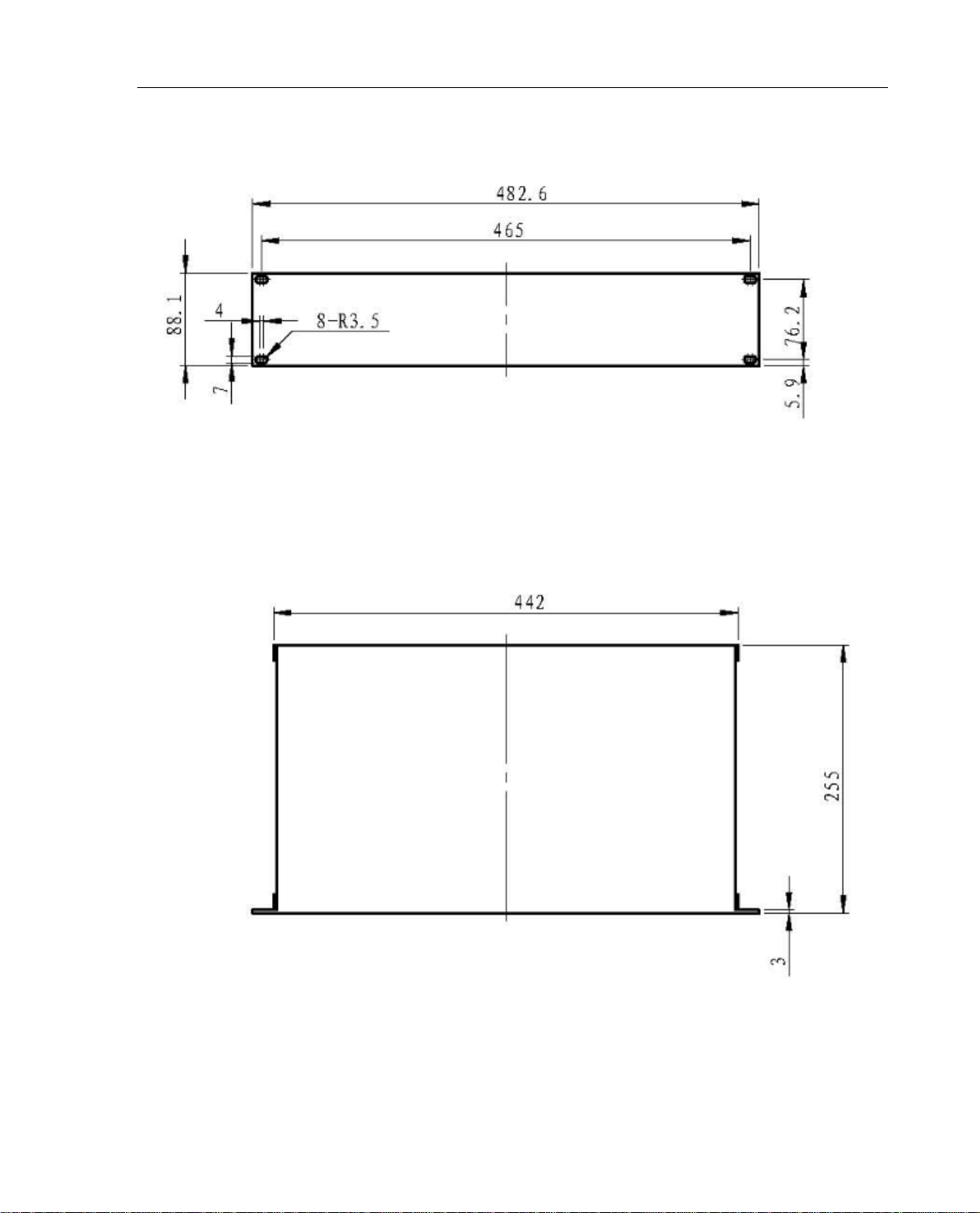
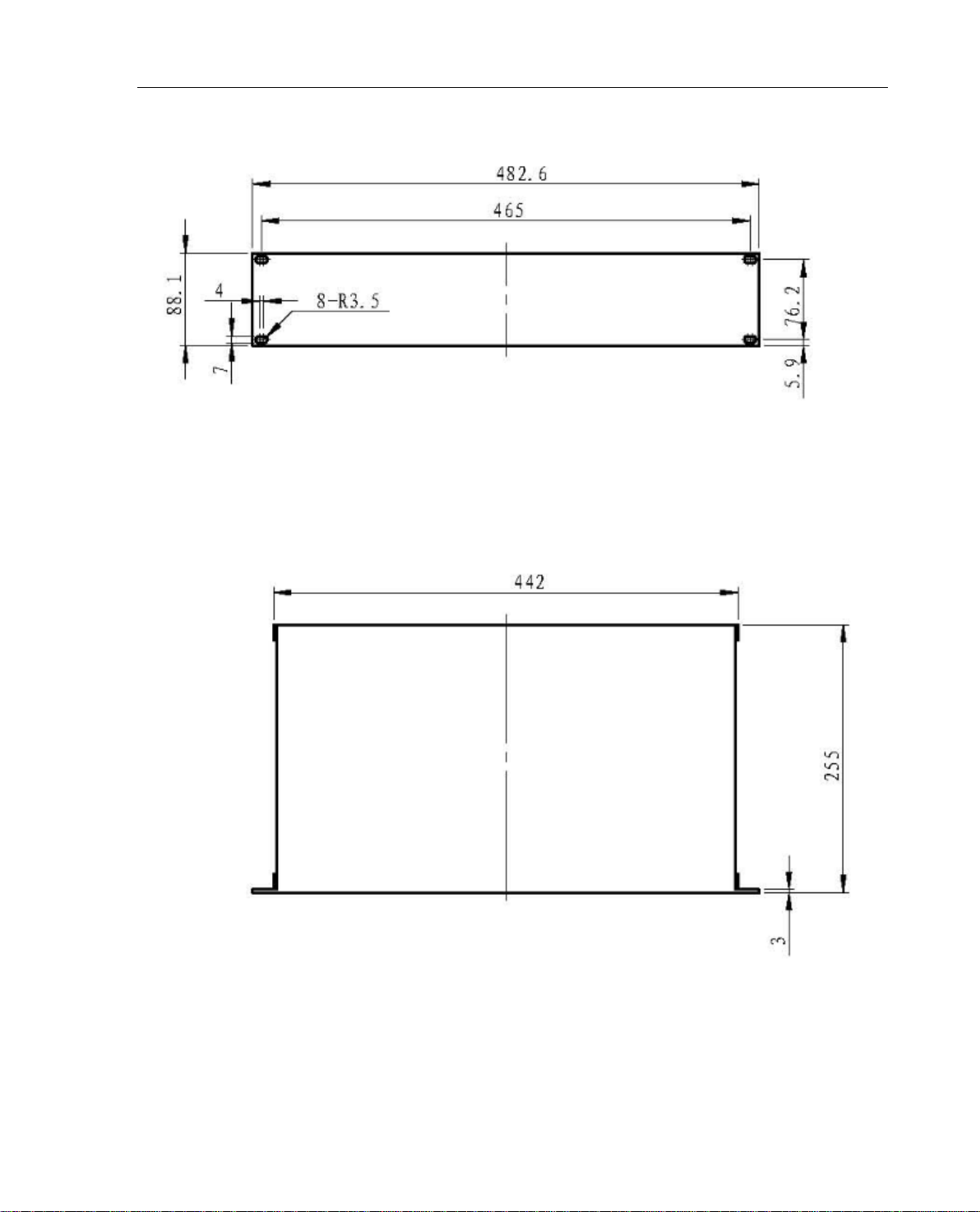
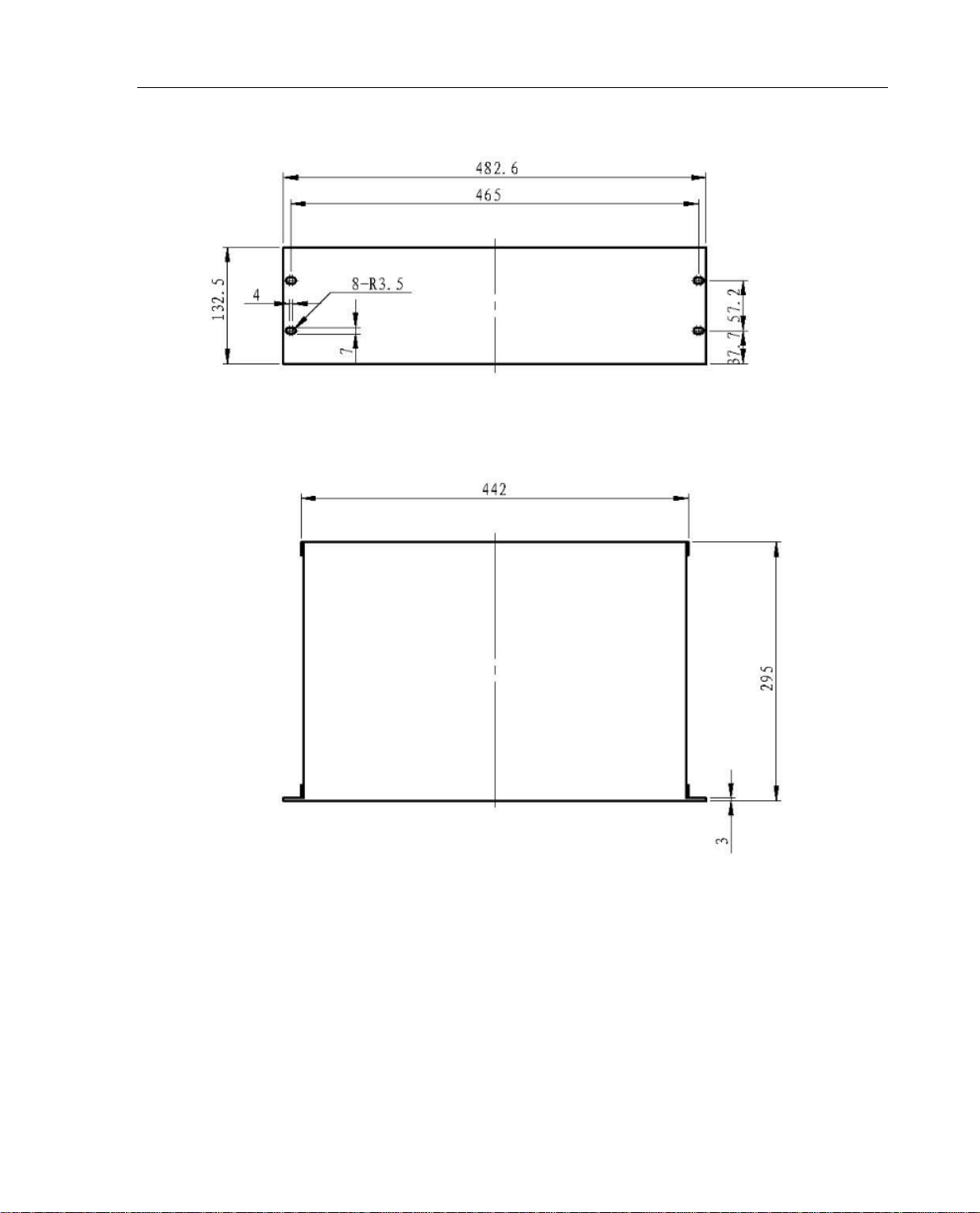
1.1 Dimension and Weight.......................................................................................................5
1.2 Weight .............................................................................................................................11
1.3 Transportation and Package............................................................................................11
1.4 Power Input .....................................................................................................................11
1.5 Use Environment.............................................................................................................11
1.6 PAC60Bi (PAC60Ci) Current Amplifier.............................................................................12
1.7 PAV120Bi Voltage Amplifier.............................................................................................12
1.8 Current/Voltage Amplitude Display ..................................................................................13
2. PAC60Bi (PAC60Ci) Current Power Amplifier .............................................................14
2.1 Basic Principle.................................................................................................................14
2.2 Function...........................................................................................................................14
2.3 High Power Current Output .............................................................................................15
2.4 Front and Rear Panels.....................................................................................................16
2.5 Terminal Definition of Rear Panel ....................................................................................18
3. PAV120Bi Voltage Amplifier.........................................................................................19
3.1 Basic Principle.................................................................................................................19
3.2 Function...........................................................................................................................19
3.3 Front and Rear Panels.....................................................................................................21
4. PAT01 Timing Output Control and Reference Signal Test Source...............................23
4.1 Basic Principle and Function ...........................................................................................23
4.2 PAT01 Front and Rear Panels.........................................................................................24
4.3 Terminal Definition...........................................................................................................25
5. How to Use Amplifier...................................................................................................27
5.1 Wiring ..............................................................................................................................27
5.2 Energizing Running .........................................................................................................27
5.3 Simulation Current/Voltage Output ..................................................................................27
5.4 Amplifier Off.....................................................................................................................28
6. Amplifier Test...............................................................................................................29
7. Appendix .....................................................................................................................30

PAC60Bi (PAC60Ci)/PAV120Bi POWER AMPLIFIER USER MANUAL
5
1.Main Technical Performance
1.1 Dimension and Weight
1.1.1 Dimension

PAC60Bi (PAC60Ci)/PAV120Bi POWER AMPLIFIER USER MANUAL
6
1.1.2 PAC60Ci
1.1.3 PAV120Bi

PAC60Bi (PAC60Ci)/PAV120Bi POWER AMPLIFIER USER MANUAL
7
1.1.4 PAD24

PAC60Bi (PAC60Ci)/PAV120Bi POWER AMPLIFIER USER MANUAL
8
1.1.5 PSS01B

PAC60Bi (PAC60Ci)/PAV120Bi POWER AMPLIFIER USER MANUAL
9
1.1.6 PSS02B or PSS05B

PAC60Bi (PAC60Ci)/PAV120Bi POWER AMPLIFIER USER MANUAL
10
1.1.7 PAT01

PAC60Bi (PAC60Ci)/PAV120Bi POWER AMPLIFIER USER MANUAL
11
1.2 Weight
1.2.1 PAP02: 82KG
1.2.2 PAC60Bi: 32.5KG or PAC60Ci: 32.5KG PA30Bi 29.5 KG
1.2.3 PAV120Bi: 21.30KG or PAV250Bi: 23KG
1.2.4 PAT01: 6.5KG
The total weight differs from the configurations and it is the sum weight of each component.
1.3 Transportation and Package
1.3.1 The panel and current/voltage amplifier should be transported separately.
1.3.2 Avoid wet and water during transpiration.
1.3.3 The wooden-made case is used to protect the machine.
1.3.4 Please handle with care during transportation.
1.4 Power Input
Power supply: 380-420V phase –phase.
Type
Item PAC60Bi(PAC60Ci) PAV120Bi
Power supply
3-phase 380V ±10%
50/60Hz
3-phase 380V ±10%
50/60Hz
Supply
capacity 2500VA 500VA
Note:
1. The instant current while running the amplifier is 7-10 times of the rated current, as a
result, the power supply should be more than 10 times of the total power.
2. The main power is focusing on the current/ voltage amplifier. So the total power of
accessories (PAT01, PAD24 and PSS01, etc) should be not more than 1,000VA.
1.5 Use Environment
Temperature range: 25℃±10℃
Relative humidity: 20%RH—85%RH
Atmosphere pressure: 86kPa—106kPa
Surrounding conditions: No dust, vibration or serious electromagnetic field interferes.

PAC60Bi (PAC60Ci)/PAV120Bi POWER AMPLIFIER USER MANUAL
12
1.6 PAC60Bi (PAC60Ci) Current Amplifier
Type
Item PAC60Bi PAC60Ci
Max. Output Current 60A RMS 30A RMS
Max. Output Power >800VA(60A output) >450VA(30A output)
Input Signal 0 -6 V RMS(±10.6Vp-p)
Differential Input Impedance 20KΩ
Gain
8A/V
4A/V
Current Precision
0.2%
(0.5A-60A)
0.2%
(0.5A-30A)
Linearity
≤0.2%
Phase Precision
0.2°
Distortion
≤0.2%
Frequency Range
DC-5kHz ± 1dB
Step Response <20μs
Input/output Delay
<
20μs
1.7 PAV120Bi Voltage Amplifier
Output Voltage
6x0 ~120V RMS
Max. Output Power
>
60VA (120V output)
Input Signal
0 -7V RMS
Differential Input Impedance 20KΩ
Gain
20V/V 10V/V
Voltage Precision
0.2%
Total Harmonic Distortion 0.2%
Linearity
≤0.1%
Phase Precision
0.2°
Frequency Range
DC-5kHz ± 1dB
Step Response
<
20μs
Input/output Delay
<
20μs

PAC60Bi (PAC60Ci)/PAV120Bi POWER AMPLIFIER USER MANUAL
13
1.8 Current/Voltage Amplitude Display
There are 3 and a half digits of true RMS values displayed for output current, voltage with the
precision of 1%.

PAC60Bi (PAC60Ci)/PAV120Bi POWER AMPLIFIER USER MANUAL
14
2. PAC60Bi (PAC60Ci) Current Power Amplifier
2.1 Basic Principle
This current amplifier is a kind of linear current power amplifier targeting at the CT characteristic of
power system, with the strengths of high accuracy, high current and quick response, which
consists of below parts mainly:
1) High-speed differential input circuit for amplifier;
2) Current power amplifier module;
3) Detection and alarm circuit, and each amplifier has a output distortion detection circuit.
4) Protection circuit, which can shut off the amplifier when its temperature is too high and will
let it resume to work when it is cooled down to a reasonable degree.
5) Cooling fan. When the temperature of the amplifier is quite low, the fan will work at low
speed for it’s better for prolonging the service life and reducing the operation noise of the fan.
2.2 Function
1) The differential input circuit can reduce the influence of the common mode noise to make it
possible that use long wires to connect across the amplifier and signal source, which will reduce
mutual effects between all amplifiers during high current output to guarantee the operation safety
of the simulator.
2) When open circuit or waveform distortion occurs in current output, the alarm light of current
distortion on the front panel will turn on.
3) Pause control function (PAUSE). The pause button on the front panel can cut off the signal input
of the amplifier. Press the pause button, the output current will become zero.
4) When the protection is activated, the input of the amplifier will be terminated and the “Overheat”
alarm light will turn on together.

PAC60Bi (PAC60Ci)/PAV120Bi POWER AMPLIFIER USER MANUAL
15
2.3 High Power Current Output
With high power control button depressed, after several seconds, the high power control button
light will turn on. By then the current amplifier can improve 20% of output power. This button can
be used in case there have high current output needed and heavy load applied.
Cautions:
1. Generally it’s not necessary to activate the high power output function, because it
may cause extra heat generated from amplifier.
2. High power output function must be inactivated as soon as the job was done. Never
let amplifier stay in high power output state for a long time.
3. Never activate the high power output function when output terminals are directly short
connected.
4. Never activate the high power output function with DC current output.
5. Never activate or inactivate the high power output function when amplifier is
producing any output.

PAC60Bi (PAC60Ci)/PAV120Bi POWER AMPLIFIER USER MANUAL
16
2.4 Front and Rear Panels
PAC60Bi Front and Rear Panels

PAC60Bi (PAC60Ci)/PAV120Bi POWER AMPLIFIER USER MANUAL
17
PAC60Ci Front and Rear Panels

PAC60Bi (PAC60Ci)/PAV120Bi POWER AMPLIFIER USER MANUAL
18
2.5 Terminal Definition of Rear Panel
Contact Signal Output
Terminal No.
1
2
3
4
5
6
7
8
Output Mode
+ -
Function
Definition
Overheat
alarm signal
output
Voltage output
overload/
short-circuit
alarm signal
Pause signal
output
Inverse time
limit signal
output
Control Signal Input
Terminal
No.
1 2 3 4 5 6
Output
Mode
+ + + COM- + -
Function
Definition Pause control
+12V input
Test
control
+12V
input
Common
terminal Test signal input
Note: Pause control and test control both are valid for high level input (5-15V).

PAC60Bi (PAC60Ci)/PAV120Bi POWER AMPLIFIER USER MANUAL
19
3. PAV120Bi Voltage Amplifier
3.1 Basic Principle
This voltage power amplifier is a linear voltage power amplifier specially targeting at the PT
characteristics of power system with the strengths of high accuracy, high voltage and quick
response, which consists of below parts mainly:
1) High-speed differential input circuit for amplifier;
2) High-performance voltage power amplifier module;
3) Distortion detection and alarm circuit. Each amplifier has the overload or output distortion
detection circuit. When overload or short-circuit situation disappears, the amplifier can resume to
work automatically.
4) Temperature protection circuit. It will terminate the amplifier as soon as the temperature of
the amplifier reaches the dangerous degree and will let it resume to automatically when it has
been cooled down to a reasonable level.
5) Temperature-controlled fan. Fan will work at low speed if amplifier temperature is certain
low, which is benefit for prolonging its service life and reducing working noise.
3.2 Function
1) The differential input circuit can reduce the influence of the common mode noise to make it
possible that use long wires to connect across the amplifier and signal source, which will reduce
mutual effects between all amplifiers during high current output to guarantee the operation safety
of the simulator.
2) Automatic output voltage distortion and overload detection circuit, which is quite capable to
protect voltage amplifier against output overload or short-circuit fault. When overload and short
circuit situation disappears, the amplifier can resume to work automatically. If overload or
short-circuit occurs, the amplifier will be terminated automatically and the overload alarm light on
the front panel will turn on.
3) Pause control function (PAUSE). The pause button on the front panel can cut off signal input of
amplifier. Press the pause button, the output of the amplifier will become zero.
4) When the overheat protection is activated, the input of the amplifier will be terminated and the

PAC60Bi (PAC60Ci)/PAV120Bi POWER AMPLIFIER USER MANUAL
20
“Overheat” alarm light on the front panel will turn on.
5) 3U0accumulation function. Ua, Uband Uccan be added up to form a 3U0signal to be outputted
via Udchannel.
6) Two gain options. User can accord to maximum voltage output value to select right gain.
This manual suits for next models
2
Table of contents
Other Ponovo Amplifier manuals

Ponovo
Ponovo PAC60Bip User manual

Ponovo
Ponovo PAV5000 User manual

Ponovo
Ponovo PAV15000 User manual

Ponovo
Ponovo PA30BI-H User manual

Ponovo
Ponovo PA460Bi User manual

Ponovo
Ponovo PA60BI User manual

Ponovo
Ponovo PA460Bi-C User manual

Ponovo
Ponovo PAV250Bip User manual

Ponovo
Ponovo PAC2000B User manual

Ponovo
Ponovo PAV120Bi User manual
Popular Amplifier manuals by other brands

Altinex
Altinex MULTITASKER MT113-100 user guide

PROART
PROART A 5024 operating instructions

AudioBahn
AudioBahn 3 SUB SERIES-PARALLEL - DIAGRAM manual

Solid State Music
Solid State Music SSM 2000 Service manual

Sutherland
Sutherland Director Line Preamp owner's manual

Altec Lansing
Altec Lansing 9442A Specifications