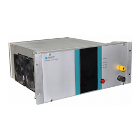
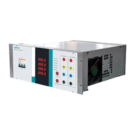
Ponovo PAC60Bip User manual

PAC60Bip Power Amplifier User Manual
1
PONOVO POWER CO., LTD
No. 139 Jinghai Third Road, BDA, Beijing, China, 100176
Office
TEL. +86 (10) 59089666
E-Mail
Info@relaytest.com
Website
www.ponovo.net
PAC60Bip
POWER AMPLIFIER USER MANUAL
VERSION: PAC60Bip-AE-1.30
DATE: MAY 2022
This manual is the publication of PONOVO POWER CO.,LTD. Any form of copy should
obtain the consent of it.
The manual represents the technology status at publication time. The product information,
directions and all technical specifications do not have contract binding. The company
subjects to changing the technical and configuration information without notice. The
company is not responsible for possible errors occurred in the manual.

PAC60Bip Power Amplifier User Manual
2
Notes:
Read User Manual before operation.
1. Carefully check all buttons are positioned correctly before startup.
1) Pause button in correct position in pressed state.
2) ON/OFF in OFF state.
2. Main supply capacity should meet the requirement; otherwise it will affect output power
of amplifier during high current output.
3. Handle the amplifier with great care and follow the symbols on the package: fragile,
handle with care, top (an arrow pointing up), keep dry and protect from shaking.
4. Never operate live signal and load cables with voltage or current output to protect the
safety of equipment and personnel.

PAC60Bip Power Amplifier User Manual
3
Content
1. General Description...........................................................................................................4
2. Main Technical Specifications..........................................................................................5
2.1 Power Supply ...........................................................................................................5
2.2 Environment Conditions .........................................................................................5
2.3 Dimension and Weight ............................................................................................5
2.4 Technical Specifications .........................................................................................6
3. Functions and Features....................................................................................................7
3.1 Basic Principle .........................................................................................................7
3.2 Functions and Features ..........................................................................................7
3.3 PAC60Bip Front and Rear Panels ..........................................................................9
3.4 Definition of Terminal Leads.................................................................................11
4. How to Use Amplifier.......................................................................................................12
4.1 Wiring ......................................................................................................................12
4.2 Running...................................................................................................................12
4.3 Current Output .......................................................................................................12
4.4 Amplifier Off............................................................................................................12
4.5 Amplifier Test Items...............................................................................................13
5. Parameter definition ........................................................................................................14

PAC60Bip Power Amplifier User Manual
4
1. General Description
The power amplifier for digital simulator in power system is required to have high linearity,
quick response, be available to all kinds of capacitive, inductive and resistive loads.
Generally power amplifier consists of two types of amplifiers: linear power amplifier and
switching power amplifier. The linear power amplifier has the strengths of high linearity,
quick response, high accuracy, good electromagnetic compatibility and the weakness of bad
performance in high current and high power cases. The switching power amplifier is quite fit
in high current, high power devices with its strength of high efficiency, but it’s weak in
linearity, small signal noise, DC offset, drift, transient response, load driving capability
aspects, which are very difficult to fix.
PAC60Bip is specially designed for R&D of power system simulation. It solves the problems
of high power of linear power amplifier and accuracy of high current output. It is adapt to
various capacitive and inductive load.

PAC60Bip Power Amplifier User Manual
5
2. Main Technical Specifications
2.1 Power Supply
Model
Item
PAC60Bip
Power supply
Customized
Power capacity
1500VA
2.2 Environment Conditions
Temperature: 25°C±10°C
Related humidity: 20%RH—85%RH
Pressure: 86 kPa—106kPa
Surrounding conditions: No dust, vibration or serious electromagnetic field interferes
2.3 Dimension and Weight
4U standard chassis H×W×D(mm): 197×364×464
Weight: 21kg

PAC60Bip Power Amplifier User Manual
6
2.4 Technical Specifications
Model
Item
PAC60Bip
Max. output current
3×60A RMS
Max. output load voltage
7V/CH
Input signal
0 - 5V RMS
Differential input impedance
20kΩ
Gain
6A/1V
Current accuracy
0.2% (0.5A-60A)
Output offset
0.2% (full range, temperature 20-30
℃
)
Distortion
≤0.2%
Pass band (±1dB)
5kHz
Frequency range
DC-5kHz±1dB
Step response
< 20μs
Hardware inspection
Open-circuit, overheat, etc

PAC60Bip Power Amplifier User Manual
7
3. Functions and Features
3.1 Basic Principle
PAC60Bip consists of the below parts mainly:
1) High-speed differential input circuit for amplifier;
2) Current power amplifier module;
3) Detection and alarm circuit: each amplifier has output open-circuit and distortion
circuit detection.
4) Protection circuit: Turn off the amplifier when the temperature is too high; It will
resume working when it is cooled down to a reasonable degree.
5) Cooling fan: when the temperature is quite low, the fan will work at a low speed for
prolonging the fan’s life-span and reducing working noise.
3.2 Functions and Features
3.2.1 Differential input circuit
The differential input circuit can reduce the influence of the common mode noise to make it
possible that use long wires to connect across the amplifier and signal source, which will
reduce mutual effects between all amplifiers during output to guarantee the operation safety
of the simulator.

PAC60Bip Power Amplifier User Manual
8
3.2.2 Open-circuit alarm function
When one current output is open-circuit or wave distortion, the alarm “I1, I2, I3”in“Current
Output” on front panel will light.
3.2.3 Pause control function
The pause button on the front panel can cut off amplifier’s signal input and amplifier output.
pressing the pause button to pause the output of the amplifier.
The input signal should be stopped before the Pause is removed. The amplifier output will
be restarted with new input signal.
3.2.4 Overheat protection function
When the overheat protection is activated, the amplifier will stop working automatically and
the “Overtemp” alarm light on the front panel will work.

PAC60Bip Power Amplifier User Manual
9
3.3 PAC60Bip Front and Rear Panels
Front Panel
1. Signal input interface
2. Ground protection
3. Current output
4. Indicators
5. ON/OFF
6. Pause: Press it and light in red. The current and voltage output will be paused.
Note: The input signal should be stopped before the Pause is removed. The amplifier
output will be restarted with new input signal.

PAC60Bip Power Amplifier User Manual
10
Rear Panel
7. Power plug
8. Ventilation
9. Ventilation

PAC60Bip Power Amplifier User Manual
11
3.4 Definition of Terminal Leads
123
4567
8 9 10 11 12
13 14 15 16
17 18 19
Definition
Pin
Related
lead Signal
1
1
I1+
2
2
I1-
3
3
I2+
4
4
I2-
7
5
I3+
8
6
I3-
12
7
I4+
13
8
I4-
16
9
I5+
17
10
I5-
18
11
I6+
19
12
I6-
Rest
/
Not used

PAC60Bip Power Amplifier User Manual
12
4. How to Use Amplifier
4.1 Wiring
Connect digital simulator system’s D/A output signals to corresponding signal channels of
current input (Refer to the Definition of terminal leads). Pay attention that the shielded layer
of the signal wire at simulator side should be grounded.
4.2 Running
Check the power supply is normal before energizing the amplifier, and the polarity of input
signal is correct. Turn on the power on the front panel after all is ready.
4.3 Current Output
Refer to the Definition of terminal leads for details.
First, press “Pause” button and connect the current output terminals to corresponding
terminals of the tester respectively. And then inactivate the pause function and input
simulation signal, the amplifier will output related current.
The formula is : Current output = Input simulation signal x gain
4.4 Amplifier Off
Stop simulation signal input firstly if users stop using amplifier. Press “Pause” buttons, and
cut off all connections of amplifier and load, lastly turn off power.

PAC60Bip Power Amplifier User Manual
13
4.5 Amplifier Test Items
Before putting into market, the amplifier is required to have strictly inspections. The test
items are: function inspection, linearity, load stability, THD, max output power,
amplitude-frequency characteristic, input/output delay and step response, etc.
Please refer to Test and Factory Report for the detailed information.

PAC60Bip Power Amplifier User Manual
14
5. Parameter definition
Notes: The voltage/current values are valid if not specified.
5.1 Output calculation value: input signal impedance x gain value
For example:1.0V×8.0A/V=8.0A 1.0V×4.0A/V=4.0A
1.0V×20.0V/V=20.0V
5.2 Measured output value: RMS of actual output
5.3 Relative error:
100%×
−
ueulationvalOutputcalc
tputvalueMeasuredou
5.4 Linearity:
2
.
max.rornegativeer
rrorpositivveeMax −
5.5 Current amplifier load stability: load resistance≈0Ω, output current I1
Load resistance ≈max. load, output current I2
5.6 Input/output delay: the time delay of 50% rising rate between input square
wave signal and the output square wave signal
5.7 Amplifier step response: the bigger value between the time of 10%-90%
rising rate and 90%-10% falling rate
Table of contents
Other Ponovo Amplifier manuals

Ponovo
Ponovo PAV5000 User manual

Ponovo
Ponovo PAV250Bip User manual

Ponovo
Ponovo PAV250Bi User manual

Ponovo
Ponovo PAV120Bip User manual

Ponovo
Ponovo PAV120Bi User manual

Ponovo
Ponovo PAC2000B User manual

Ponovo
Ponovo PA460Bi-L User manual

Ponovo
Ponovo PA30BI-H User manual

Ponovo
Ponovo PA460Bi-C User manual

Ponovo
Ponovo PAC60Bi User manual