Pope Lawn Genie 30cc User manual

To reduce the risk of injury, the user must read and understand the operator’s manual.
Save this manual.
30cc Lawn Genie Line Trimmer
Model No 101PLT30HC
Operator’s Manual
WARNING:

Before you use your new Line Trimmer, read this manual carefully to learn how
to operate and maintain your product correctly. Reading this manual will help
you and others avoid personal injury and damage to the product. Although
Pope designs safe state-of-the-art products, you are responsible for using the
product properly and safely. You are also responsible for training persons you
allow to use the product about safe operation.
READ THIS INFORMATION
STOP
Introduction
Thank you for purchasing a Pope®product.
We would like you to be completely satisfied with your new product, so feel free to contact an
authorised service dealer for help with service, genuine Pope parts or other information you may
require.
The Pope warning system in this manual identifies potential hazards and special safety messages
that help you and others avoid personal injury, even death. DANGER, WARNING and CAUTION are
signal words that identify the level of hazard. However, regardless of the hazard, be extremely careful.
Two other words “Important” and “Note” highlight other valuable information.
Signal Word Explanation
DANGER Indicates an imminently hazardous situation which, if not avoided,
will result in death or serious injury.
WARNING Indicates a potentially hazardous situation which, if not avoided,
could result in death or serious injury.
CAUTION Indicates a potentially hazardous situation which if not avoided,
could result in death or serious injury.
Important Advises you of important information or instructions vital to the
operation or maintenance of the equipment.
Note Advises you of additional information concerning the operation or
maintenance of the equipment.

Contents
Safety Rules ............................................................................................................................................. 4
Symbols ..................................................................................................................................................... 5
Specifications ......................................................................................................................................... 6
Applications ............................................................................................................................................. 6
Features ..................................................................................................................................................... 7
Unpacking ................................................................................................................................................ 8
Assembly ................................................................................................................................................... 9
Attaching the Upper Shaft with Engine to the Lower Bent Shaft Cutting Head................. 10
Removing the Bent Shaft from the Shaft with Engine............................................................... 11
Attaching the Storage Hanger......................................................................................................... 11
Attaching the Front Handle ............................................................................................................. 12
Attaching the Grass Deflector Shield............................................................................................. 12
Operation .................................................................................................................................................. 13
Mixing the Fuel ................................................................................................................................... 13
Filling the Tank ................................................................................................................................... 13
Starting the Product........................................................................................................................... 14
– Engine Cold......................................................................................................................... 14
– Engine Warm....................................................................................................................... 15
– Stopping the Product ...................................................................................................... 15
– Starting a Flooded Engine .............................................................................................. 15
Operating the Trimmer ......................................................................................................................16
Cutting Tips.......................................................................................................................................... 16
To Advance the Cutting Line ...........................................................................................................17
Grass Deflection Line Trimming Cut-Off Blade............................................................................ 17
Maintenance ............................................................................................................................................ 18
Cleaning the Product ........................................................................................................................ 18
Replacing and Cleaning the Air Filter ............................................................................................ 19
Spark Plug Replacement.................................................................................................................. 19
Cutting Line Replacement ............................................................................................................... 20
Storing the Product .............................................................................................................................. 21
Troubleshooting ..................................................................................................................................... 22
Warranty .................................................................................................................................................... 23

■Physical Condition of the Operator. Do
not operate this product when tired, ill or
under the influence of alcohol, drugs or
medication.
■Clothing Requirements. Always wear long
heavy pants, boots and gloves. Do not wear
loose clothing, jewellery, short pants, sandals
or go barefoot. Secure hair so that it is above
shoulder level to avoid entanglement in
moving parts.
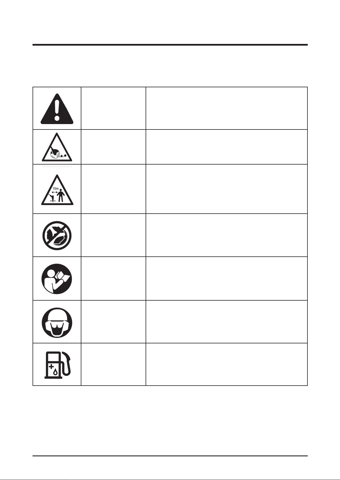
■Protective Accessories Requirements.
Wear safety eye protection when operating
this product. Wear hearing protection during
extended periods of operation.
■Condition of Product Before Use. Inspect
the product before each use. Replace
damaged parts. Check for fuel leaks. Make
sure all fasteners are in place and secure.
Replace cutting attachment parts that are
cracked, chipped or damaged in any way.
Make sure the cutting attachment is properly
installed and securely fastened. Be sure the
cutting attachment guard is properly installed
and in the position recommended by the
manufacturer. Use only flexible, non-metallic
line recommended by the manufacturer. For
example, never use wire or wire rope which
can break off and become a dangerous
projectile.
■Proper Stance. Keep firm footings and
balance. Do not overreach. Keep the cutting
attachment below waist level. Keep all parts
of your body away from the rotating cutting
attachment and hot surfaces.
■Exhaust Gases. Never start or run the
product inside a closed room or building:
breathing exhaust fumes can cause illness or
death.
Safety Rules
Read and understand all instructions. Failure to follow all instructions may result in
serious personal injury as well as damage to product.
4
WARNING:
■Fuelling. Mix and pour fuel outdoors where
there are no sparks or flames. Slowly remove
the fuel cap only after stopping the engine.
Do not smoke while fuelling or mixing fuel.
Wipe spilled fuel from the product. Move at
least 9 m from the fuelling source and site
before starting the engine.
■Work Area. Clear the area to be cut before
each use. Remove all objects such as rocks,
broken glass, nails, wire, or string that can be
thrown or become entangled in the cutting
attachment. Clear the area of bystanders,
pets and children. At a minimum, keep all
bystanders, pets and children outside a
15 m radius. Because there still may be a
risk to bystanders from thrown objects,
bystanders should be encouraged to wear
eye protection. If you are approached while
operating the product, stop the engine or for
those products equipped with a clutch be
sure the cutting attachment has stopped
moving.
■Dangerous Environments. To avoid falling,
do not use the product in damp or wet
locations.
■Controlling the Product. During carburettor
adjustments the cutting attachment may
spin. Therefore you should wear protective
equipment and observe all safety instructions
when adjusting the carburettor. For products
equipped with a clutch, be sure the cutting
head has stopped rotating before setting
down or adjusting the product. Maintain
proper control until the cutting head has
completely stopped rotating.
■Use the Right Product. Use the product for
the intended purpose only.

Symbol Name Explanation
Safety Alert Indicates danger, warning or caution. Attention is
required in order to avoid serious personal injury.
May be used in conjunction with other symbols or
pictographs.
Thrown Objects Thrown objects can cause severe injury.
Wear protective clothing and boots.
Keep Bystanders Keep all bystanders, especially children and pets,
Away at least 15 metres from the operating area.
No Blade Do not install any type of blade on this product. Use only
flexible, non-metallic line recommended by the
manufacturer.
Read Operator’s Read the Operator’s Manual before starting or
Manual operating this product. Failure to follow operating
instructions and safety precautions in the Operator’s
Manual can result in serious injury.
Eye and Ear Thrown objects can cause severe eye injury.
Protection Wear eye protection when operating this product.
Wear hearing protection during extended periods
of operation.
Petrol and Oil Use unleaded petrol intended for motor vehicle use with
an Octane rating of 87 ([R + M] / 2) or higher. This
product is powered by a 2 stroke engine and requires
pre-mixing and 2 stroke oil.
Symbols
The following symbols are located on the product. Please study them and learn their meaning.
Proper interpretation of these symbols allows you to operate the product better and safer.
5

Specifications
6
Model 101PLTHC
Curved Shaft Line Trimmer
Engine: 30 cc Two Stroke
Cutting Width: 400 mm
Line Size: 2.00 mm
Weight (Dry): 5.35 kg
Fuel Tank Capacity: 0.41 litres
Applications
Use this product for the following applications:
■Cutting grass, weeds and light undergrowth.
■Edging along sideways and driveways.
■Do not attempt to use this product as a drive unit for other work tools or toolkits of any kind.

Features
Do not attempt to modify this product or create accessories not recommended for
use with this product. Any such alteration or modification is misuse and could result in
a hazardous condition leading to serious personal injury and will void your guarantee.
7
Before using the product, familiarise yourself with all operating features and safety requirements.
However, do not let familiarity with the product make you careless.
Exercise caution when using the product. Careless actions, for even a fraction of a
second, can result in serious personal injury.
WARNING:
WARNING:
Engine
The engine is powerful and easy to start. It is
effectively counterbalanced, which allows for
less vibration and more durability.
Dual line
The dual line permits more efficient cutting than
a single line.
Grass Deflector
The grass deflector helps protect you from
flying debris. The deflector also includes a
cutting blade that automatically trims the line to
the correct length.
Ergonomic Handle Design
The design of the product provides for easy
handling. It is designed for comfort and ease of
grasp when operating in different positions and
at different angles.
Your new product is equipped with the following features.

Unpacking
Instructions
■Carefully remove the product from the box.
■Inspect the product carefully to make sure
no breakage or damage occurred during
shipping.
■Do not discard the packing material until
you have carefully inspected and
satisfactorily operated the product.
■If any parts are damaged or missing,
please call 1300 134 880.
8
Packing List
Model No. 101PLT30HC
Upper shaft with 30cc Line Trimmer engine
Lower Bent Shaft
Grass Deflector Shield
Loop Handle
Spark Plug Wrench, Tube Spanner with Phillips
head Screwdriver attachment (1)
Hanger Cap
Operator’s Manual
WARNING:
If any parts are missing, do not operate the product until the missing parts are replaced.
Failure to do so could result in serious personal injury.

Assembly
9

Assembly – continued
Attaching the Upper Shaft with
Engine to the Lower Bent Shaft
Cutting Head
See Fig. 2
10
Fig. 2
WARNING:
Be certain that the connecting spring
is located into the drive shaft of the
upper shaft.
4. Tighten the coupler knob securely.
WARNING:
Be certain the knob is fully tightened
before operating. Check for tightness
during use to avoid serious personal
injury.
WARNING:
Be careful when handling the blade.
It is sharp. Failure to heed this warning
can result in serious personal injury.
Follow these steps to attach the two shafts
together.
The lower bent shaft connects to the upper
shaft with engine by means of a coupler
device.
1.
Loosen the knob on the coupler of the upper
shaft with the engine and remove the hanger
cap from the lower bent shaft.
2.
Press in the lock button and slide off the
hanger cap.
3.
Press in the lock button located on the lower
shaft. Align the button with the guide recess
on the upper shaft coupler and slide the two
shafts together. Rotate the lower shaft until
the button locks into the positioning hole.
NOTE: If the button does not release
completely in the positioning hole, the shafts
are not locked into place. Slightly rotate from
side to side until the button is locked into
place.

Assembly – continued
11
Removing the Bent Shaft from the Upper Shaft with Engine
Follow these steps to remove or change the attachment.
1.
Loosen the knob.
2.
Push in the button and twist the shafts to remove and separate ends.
Fig. 3
Attaching the Storage Hanger
See Fig. 3
Follow these steps to attach the storage
hanger cap.
There are two ways to hang your attachment
for storage.
1.
To use the hanger cap, push in the button
and place the hanger cap over end of lower
end attachment shaft. Slightly rotate the
cap from side to side until the button locks
into place.
2.
The secondary hole in the attachment shaft
can be used for hanging purposes as well.

Assembly – continued
12
Fig. 5
Fig. 4
The line cutting blade on the grass
deflector is sharp. Avoid contact with
the blade. Failure to avoid contact can
result in serious personal injury.
WARNING:
Attaching the Grass Deflector
Shield
See Fig. 5
Follow these steps to attach the grass deflector
shield.
1. Remove the hex head cap screw stored in
the grass guard for transit.
2. Press the grass guard onto the bottom of
the curved shaft as shown.
3. Re-insert the hex head cap screw through
the grass guard and the bracket on the
curved shaft.
4. Place the flat washer and lock washer on
the hex head cap screw.
5. Place the hex nut on the hex head cap
screw and tighten securely with the tube
spanner found at the opposite end of the
spark plug spanner.
Attaching the Front Handle
See Fig. 4
Follow these steps to attach the front handle.
1. Remove the front handle, bolt, flat washer,
lock washer and wing nut from the
Owner’s Kit.
2. Install the front handle onto the top side of
the drive shaft housing and move it to a
comfortable position.
3. Place the bolt through the front of the
handle.
NOTE: The hex bolt head fits inside the hex
recess molded into one side of the handle.
4. Install the flat washer, lock washer and
wing nut.
5. Tighten wing nut securely.

13
Operation
Mixing the fuel
This product is powered by a 2 stroke engine
and requires pre-mixing petrol and 2 stroke oil.
The oil mix should be 50:1. Never mix petrol
and oil directly in the engine tank.
Use unleaded petrol intended for motor vehicle
use with an Octane rating of 87 ( [R + M] / 2) or
higher. Purchase fuel from a reputable fuel
supplier.
Use an approved mixing container to mix the
oil and petrol in the correct quantities.
Petrol Oil
0.5 litre 10 ml
1 litres 20 ml
2 litres 40 ml
3 litres 60 ml
4 litres 80 ml
Mix only enough fuel for your immediate needs.
Fuel should not be stored for more than 30 days.
Follow these steps to mix the fuel:
1. Use an approved mixing container for
mixing fuel.
2. Mix the 2 stroke engine oil with unleaded
petrol in the container provided at the rate
of 50 parts petrol to 1 part oil.
3. Mix the fuel thoroughly and also each time
before re-fuelling.
4. Mix in small quantities. Do not mix more
fuel than you expect to use within a 30 day
period.
5. Store fuel only in a clean, safe, approved
container for petrol.
Follow these steps to fill the tank:
1. Clean the surface around the fuel tank to
prevent contamination.
2. Loosen the fuel cap slowly and rest the
cap on a clean surface.
3. Pour the fuel mixture carefully into the tank.
4. Clean and inspect the gasket.
NOTE: Replace the fuel cap if the gasket is
damaged.
5. Install the fuel cap and hand tighten.
Always stop the engine before filling
the tank. Never add fuel to a
machine with a running or hot
engine. Move at least 9 m away from
the refuelling site before starting the
engine. Do not smoke while filling the
tank. Do not add fuel to the tank
close to an open fire or sparks. Never
add fuel to the tank in a closed or
non-ventilated area.
Filling the Tank
6. Wipe spilled fuel from the product.
7. Move at least 9 metres away from tank
refuelling site before starting the product.
NOTE: It is normal for the engine to emit
smoke during first use.
Check for fuel leaks. If you find any
leaks, correct the problem before
using the product.
Petrol is extremely flammable and
explosive. A fire or explosion from
petrol will burn you and others.
DANGER: WARNING:
WARNING:
50:1

Fig. 9
14
Operation – continued
The recoil starter can be damaged by
abuse.
Never pull the starter cord to its full
length.
Always engage the starter before
cranking the engine.
Always rewind the starter cord slowly.
To Start a Cold Engine
See Figures 8, 9 and 10
Follow these steps to start a cold engine:
See Fig. 8
1. Lay the product on a flat bare surface.
2. Press the rocker start/stop switch to
START. (see Figure 8).
3. Push the primer bulb approximately seven
times until fuel comes into the primer pump
(see Figure 9).
4. Set the choke lever down to the “full”
choke position (see Figure 10).
5. Press the throttle lock button until it locks
into place.
6.
Holding the machine handle firmly, pull the
starter cord slowly until you feel the starter
engage.
7. Start the engine by pulling the starter cord
upward rapidly. If necessary, repeat step 6
two or three times until the engine fires.
8. Lift the choke lever up to half choke (see
Figure 10). Excessive cranking at full choke
lever will cause the engine to flood making
it difficult to start.
9. Pull the starter cord upward rapidly until
the engine starts.
10. Let it run for 30 seconds before moving the
choke lever fully up to the “run” position.
11. If the product does not start, repeat the
steps 8 and 9.
WARNING:
Operating the machine with loose,
missing or damaged components
could allow the engine to over-speed,
possibly causing serious engine
damage.
Inspect the entire machine for
damaged, loose or missing
components or fastenings and repair
as necessary.
CAUTION:
Fig. 8
Starting the Product
Starting the product depends on whether the engine is cold or warm.

15
IMPORTANT: For maximum line trimmer
performance and operating life, allow engine to
warm before use.
1. Run the engine at idle speed until
operating temperature is reached
(2-3 minutes).
2. The machine should now be ready for use.
To start a warm engine:
Follow these steps to start a warm engine.
1. Lay the product on a flat, bare surface.
2. Slide the switch to the ON position.
3. Push the primer bulb up to eight times.
4. Pull the starter cord.
NOTE: If the product does not start, repeat the
previous steps. Check that the fuel tank has
sufficient fuel for the engine to start.
Stopping the Product
Starting the product depends on whether the
engine is cold or warm.
1. Release the throttle control.
2. Slide the switch to the OFF position.
Incorrect spark plug installation can result in serious engine damage.
WARNING:
Operation – continued
Fig. 10
Starting a Flooded Engine
1. Disconnect the spark plug boot and use
the spark plug wrench supplied to remove
the plug in a counter-clockwise direction.
2. If the spark plug is fouled or is soaked with
fuel, clean or replace the plug as required.
3. Turn the product so that the spark plug
hole is aimed at the ground.
4. Clear excess fuel from the combustion
chamber by cranking the engine several
times while the spark plug is removed.
5. Install the spark plug and firmly tighten it
with the spark plug wrench supplied. DO
NOT OVERTIGHTEN.
6. Reconnect the spark plug boot.

16
Operating the Trimmer
See Fig. 11
BEFORE EACH USE
■Remove dirt and debris from the product
exterior.
■Inspect the engine, tank and hoses for
possible fuel leaks and repair as necessary.
■Inspect the engine cooling fins for
accumulation of debris and clean as
necessary.
■Inspect the entire machine for damage,
loose and missing components or
fasteners and repair as necessary.
Follow these steps to operate the line trimmer:
1. Start the trimmer.
2. Hold the trimmer at waist level with your
right hand on the trigger handle and your
left hand on the front handle.
3. Place the product on the right side of your
body with the engine behind and away
from your body.
4. Keep a firm grip with both hands while in
operation.
5. Cut tall grass and weeds down in a right-
to-left motion. This will prevent grass
wrapping around the shaft housing and
string head, which may cause damage
from overheating.
If grass becomes wrapped around the string
head, STOP THE ENGINE, disconnect the
spark plug wire, and remove the grass.
NOTE: Prolonged cutting at partial throttle will
result in oil dripping from the muffler.
Cutting Tips
1. Keep the trimmer tilted toward the area
being cut; this is the best cutting area.
2. The curved shaft trimmer cuts when
passing the unit from right to left. This will
avoid throwing debris at the operator.
Avoid cutting in the dangerous area shown
in Figure 12.
3. Use the tip of the line to do the cutting; do
not force line head into uncut grass.
4. Wire and picket fences cause extra line
wear, even breakage. Stone and brick
walls, curbs and wood will wear the cutting
line rapidly.
5. Avoid trees, shrubs, tree bark and wood
moldings.
Operation – continued
Fig. 11
To avoid burns from hot surfaces,
never operate unit with the bottom of
the engine above waist level.
WARNING:
Fig. 12

Operation – continued
17
To Advance the Cutting Line
Follow these steps to advance the cutting line.
The cutting line is controlled by tapping the cutting head on grass while running engine at full throttle.
1. Run the engine at full throttle.
2. Tap the spool retainer on the ground to advance line. The line advances each time the spool
retainer is tapped.
Do not hold the spool retainer on the ground.
NOTE: The line trimming cut-off blade on the grass deflector will cut the line to the correct length.
Fig. 13
Grass Deflector Line Trimming
Cut-Off Blade
See Fig. 13
1. The trimmer is equipped with a line
trimming cut-off blade on the grass
deflector.
2. For best cutting, advance line until it is
trimmed to length by the cut-off blade.
3. Advance the line whenever you hear the
engine running faster than normal, or when
trimming efficiency diminishes. This will
maintain best performance and keep the
line long enough to advance properly.

Maintenance
18
Emissions Maintenance Schedule
Maintenance, replacement or repair of the emission control device and systems may be
performed by any recognised Pope Service Centre.
Before performing any maintenance on this machine, stop the engine and disconnect
the spark plug wire.
WARNING:
Emission Part
Fuel Tank Assembly
(includes Fuel Lines, Fuel
Cap and Fuel Filter)
X
X
XX
Clean Air Filter
Replace Spark Plug
Inspect before
each use Every 10 hours Every 10 - 15 hours
or yearly
BEFORE EACH USE:
■Remove dirt and debris from the product
exterior.
■Inspect the engine, tank and hoses for
possible fuel leaks and repair as necessary.
■Inspect the engine cooling fins for
accumulation of debris and clean as
necessary.
■Inspect the entire machine for damage,
loose and missing components or
fasteners and repair as necessary.
CLEANING THE PRODUCT:
■Stop the product before cleaning.
■Clean the exterior of the product with a
damp cloth.
■Avoid using solvents when cleaning plastic
parts. Most plastics are susceptible to
damage from various types of commercial
solvents and may be damaged by their
use.

Maintenance – continued
19
Fig. 15
Fig. 14
Replacing and Cleaning the
Air Filter
See Fig. 14 and 15
11. Stop the engine.
12. Remove the spark plug boot.
13. Loosen the air cleaner cover by turning the
wing screw counter clockwise.
14. Remove the air filter cover.
15. Remove the air filter element.
16. Inspect the element. If the element is
distorted or damaged replace it with a new
one.
17. Wash the element in warm soapy water
and squeeze dry.
18. Replace the air filter (fits only one way).
19. Replace the air filter cover.
10. Tighten the air filter cover by turning the
knob clockwise.
11. Replace the spark plug boot.
Spark Plug
■This engine uses a NHSP LD L7T with an
electrode gap of 0.63 mm. Use an exact
replacement and replace annually.

Maintenance – continued
20
Replacing the Cutting Line
See Fig. 16, 17, 18 and 19
Follow these steps to replace the cutting line
11. Stop the trimmer.
12. Disconnect the spark plug boot.
13. Hold the bump feed and unscrew the
spool retainer.
14. Remove the spool retainer by turning
anti-clockwise and remove the spool from
the springhead.
NOTE: Keep the spring attached to the spool.
15. Remove any old line remaining on the
spool.
16. Cut 2 pieces of line, each approximately
5 m long.
17. Insert a piece of line into the slot in the
spool.
18. Wind the line around following the direction
of the arrows on the spool, filling one half
only.
19. Ensure that about 15 cm of line is not
wound. Do not overfill the spool. There
should be at least 6 mm space between
the wound line and the outside edge of the
spool.
10. Secure the line end temporarily in the slots
on the upper/bottom flange.
11. Repeat steps 7 - 10 for the line, filling the
other half of the chamber.
12. NOTE: Ensure that both cutting lines are
wound in the same direction and that the
lines do not cross.
13. Feed each end of the line through opposite
metal eyelets.l
14. Before pulling through completely, ensure
line is released from temporary holding slot.
15. Push spool firmly back in recess and
secure the spool retainer in position.
NOTE: Check that the bump feed head is
locked in place and is installed correctly back
on to the drive shaft.
NOTE: If insufficient line is protruding from the
bump feed head, depress bump feed head and
pull on line to manually advance the line and to
check for proper reassembly of the bump feed
head.
Make sure the trimmer heads has
fully stopped rotating. Contact with a
rotating trimmer head could cause
personal injury.
WARNING:
Fig. 16
Fig. 17
Fig. 18
Fig. 19
This manual suits for next models
1
Table of contents
Other Pope Trimmer manuals