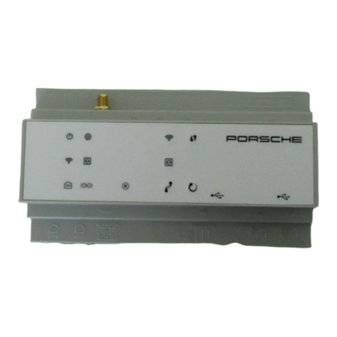
Porsche Home Energy Manager User manual

9Y0067790B
Porsche Home Energy Manager
9Y0.067.790.B - ROW
Porsche Home Energy Manager
9Y0.915.686/.A/.B/.C/.D/.E

9Y0.067.790.B - ROW 09/2021
Porsche, the Porsche Crest, Panamera, Cayenne and
Taycan are registered trademarks of Dr. Ing. h.c. F.
Porsche AG.
Printed in Germany.
Reprinting – even of excerpts – or duplication of any
kind are only permissible with the written authorisa-
tion of Dr. Ing. h.c. F. Porsche AG.
© Dr. Ing. h.c. F. Porsche AG
Porscheplatz 1
70435 Stuttgart
Germany
Driver’s Manual
Always keep this operating manual and hand it over
to the new owner if you sell your charger.
Due to dierent requirements in various countries,
the information in the thumb index tabs of this ma-
nual will be dierent. To ensure that you are reading
the thumb index tab that applies to your country,
compare the article number of the charger shown in
the “Technical Data” section with the article number
on the identication plate on the charger.
Further instructions
For information on tting the basic wall mount and
charging dock and for the electrical installation of
the Porsche charger, please refer to the installation
instructions.
Suggestions
Do you have any questions, suggestions or ideas re-
garding your vehicle or this manual?
Please write to us:
Dr. Ing. h.c. F. Porsche AG
Vertrieb Customer Relations
Porscheplatz 1
70435 Stuttgart
Germany
Equipment
Because our vehicles undergo continuous develop-
ment, equipment and specications may not be as
illustrated or described by Porsche in this manual.
Items of equipment are not always according to the
standard scope of delivery or country-specic vehicle
equipment
For more information on retrot equipment, please
contact a qualied specialist workshop. Porsche re-
commends a Porsche partner as they have trained
workshop personnel and the necessary parts and
tools.
Because of dierent legal requirements in individual
countries, the equipment in your vehicle may vary
from what is described in this manual. If your Porsche
is tted with any equipment not described in this ma-
nual, your qualied specialist workshop will be glad to
provide information on the correct operation and care
of the items concerned.

EN Home Energy Manager
Good to know – Owner’s Manual. . . . . . . . . . . 2
FR Home Energy Manager
Bon à savoir – Manuel du propriétaire. . . . . 39
ES
Home Energy Manager
Información importante: Manual del propie-
tario. . . . . . . . . . . . . . . . . . . . . . . . . . . . . . . . . . . . . 77
PT Home Energy Manager
É bom saber – Manual do proprietário. . . 116
TR Home Energy Manager
Bilmeniz gerekenler – Sürücü El Kitabı. . . 154
RU Home Energy Manager
Полезно знать — руководство. . . . . . . . . 190
UK Home Energy Manager
Корисна інформація — посібник. . . . . . . 230
VI
Thiết bịquản lý năng lượng gia đình
Điều cần biết – Hướng dẫn sửdụng dành
cho người lái. . . . . . . . . . . . . . . . . . . . . . . . . . . 269
HE להנמהיגרנאהלש Home
בוטתעדל–תוארוההלעפהגהנל . . . . . 307
AR
- . . . . . . . . . . . . 343
JA ホーム電力マネージャー
Good to know - 取扱説明書. . . . . . . . . . . . . . . 380
KO 홈전력 관리자
Good to know – 사용 설명서. . . . . . . . . . . . . . 417
ZH 家庭电源管理器
保时捷– 车主指南 – 驾驶手册. . . . . . . . . . . 451
ZH 住家電源管理器
Good to know – 車主手冊. . . . . . . . . . . . . . . . 484
TH Home Energy Manager
– . . . . . . . . . . . . . . . . . . . . 516
DE Certications
. . . . . . . . . . . . . . . . . . . . . . . . . . . . . . . . . . . . . . . . . 551

About this Owner’s Manual

3
DANGER
WARNING
CAUTION
NOTICE
Warnings and symbols
Dierent types of warnings and symbols are used in
this manual.
Serious injury or death
Failure to observe warnings in the "Danger" category
will result in serious injury or death.
Possible serious injury or
death
Failure to observe warnings in the "Warning" cate-
gory can result in serious injury or death.
Possible moderate or mi-
nor injury
Failure to observe warnings in the "Caution" category
can result in moderate or minor injuries.
Vehicle damage possible
Failure to observe warnings in the "Notice" category
can result in damage to the vehicle.
Information
Additional information is indicated using the word
"Information".
bPrerequisites that must be met in order to use a
function.
eInstructions that must be followed.
1. Instructions are numbered in cases where a se-
quence of steps must be followed.
2. Instructions that must be followed on the cen-
tral display.
g Indicates where you can nd more information on a
topic.

4
English
To the Operating instructions
Key to pictograms. . . . . . . . . . . . . . . . . . . . . . . . . . . . . . . 5
Data protection notice. . . . . . . . . . . . . . . . . . . . . . . . . . . 5
Product information. . . . . . . . . . . . . . . . . . . . . . . . . . . . . . 5
Further information. . . . . . . . . . . . . . . . . . . . . . . . . . . . . . 5
Safety
Safety principles. . . . . . . . . . . . . . . . . . . . . . . . . . . . . . . . . 6
Intended use. . . . . . . . . . . . . . . . . . . . . . . . . . . . . . . . . . . . 6
Qualication of Personnel. . . . . . . . . . . . . . . . . . . . . . . . . 7
Scope of supply. . . . . . . . . . . . . . . . . . . . . . . . . . . . . . . . . . . 8
Scope of supply
Access Data. . . . . . . . . . . . . . . . . . . . . . . . . . . . . . . . . . . . . 9
Overview
Connection diagram. . . . . . . . . . . . . . . . . . . . . . . . . . . . 10
Displays and controls. . . . . . . . . . . . . . . . . . . . . . . . . . . 11
Getting started
Getting started. . . . . . . . . . . . . . . . . . . . . . . . . . . . . . . . . 12
Connecting to the Device. . . . . . . . . . . . . . . . . . . . . . . 12
Logging in as Customer Service. . . . . . . . . . . . . . . . . 13
Starting Initial Installation. . . . . . . . . . . . . . . . . . . . . . . 14
Adapting Home Setup. . . . . . . . . . . . . . . . . . . . . . . . . . 19
Setup
. . . . . . . . . . . . . . . . . . . . . . . . . . . . . . . . . . . . . . . . . . . . . . . 22
Operation
. . . . . . . . . . . . . . . . . . . . . . . . . . . . . . . . . . . . . . . . . . . . . . . 23
Opening the web application. . . . . . . . . . . . . . . . . . . . 23
Logging in as Home User. . . . . . . . . . . . . . . . . . . . . . . 24
Logging into the web application. . . . . . . . . . . . . . . . 24
Operating the web application. . . . . . . . . . . . . . . . . . . 24
Operation
Opening the web application via the hotspot. . . . . . 30
Managing the Home Setup. . . . . . . . . . . . . . . . . . . . . . 30
Adding an EEBus device. . . . . . . . . . . . . . . . . . . . . . . . . 30
Checking the functionality. . . . . . . . . . . . . . . . . . . . . . 30
Malfunctions. . . . . . . . . . . . . . . . . . . . . . . . . . . . . . . . . . . . 31
Maintenance. . . . . . . . . . . . . . . . . . . . . . . . . . . . . . . . . . . . . 32
Disposal of the product. . . . . . . . . . . . . . . . . . . . . . . . . . 33
Technical Data
Identication plate. . . . . . . . . . . . . . . . . . . . . . . . . . . . . . 35
Manufacturing information. . . . . . . . . . . . . . . . . . . . . . 36
Index. . . . . . . . . . . . . . . . . . . . . . . . . . . . . . . . . . . . . . . . . . . . 37

5
To the Operating instructions
Key to pictograms
Depending on the country, various pictograms may
be attached to the energy manager.
Dispose of the energy manager in compli-
ance with all applicable disposal regulations.
Risk of electric shock due to improper use.
Observe the operating and installation in-
structions provided, particularly the warn-
ings and safety instructions.
Observe all the warnings set out in the in-
structions and on the energy manager.
Data protection notice
To ensure that your Porsche charging equipment can
communicate properly and is always up-to-date, the
charging equipment will send the following equip-
ment-specic data to Porsche in encrypted form at
regular intervals and process this data there: device
ID, brand, generation, device type and soware ver-
sion.
If you would also like to have the option of using
other Porsche Connect Services for the charging
equipment, you must pair your charging equipment
to your Porsche ID account, which is available from
the Porsche Connect distributor in selected markets.
While using Porsche Connect services, the follow-
ing personal data and other device-specic data re-
quired for the provision of the services is sent to
Porsche and processed there: customer ID, statistics,
device status, connection status and time stamp of
when communication was last established. You will
nd more detailed information on the general terms
and conditions and the privacy policy at www.por-
sche.com/connect-store. The regular transmission
of data for your charging equipment can incur addi-
tional costs with your Internet supplier. The data you
have saved at Porsche can be irrevocably deleted
using My Porsche. Some of the Porsche Connect
Services for the Porsche charging equipment are not
available in all countries due to technical or legal
restrictions.
Product information
The energy manager performs energy management
in combination with Porsche charging equipment
that supports this function.
The energy manager individually measures and eval-
uates the available power and the relevant power
consumption. Via an interface, the energy manager
communicates with the Porsche charging equipment
and informs it of the energy costs and of how much
power can be made available to the hybrid or electric
vehicle for charging.
During charging, the energy manager updates the
maximum available charging current in real time on
the basis of the latest data.
The qualied electrician sets up the energy manager
for you via a web application and sets all the required
values there. In this way, the electrical installation
is protected against overload and the vehicle can
be charged cost-eectively. This function is only pro-
vided however, when dierent electricity taris/pri-
ces and/or an existing photovoltaic system are used.
Once vehicle charging is started, the negotiation
phase begins and the energy manager generates
price and output tables in accordance with the cur-
rent standard specications of ISO/IEC15118.
Communication between the energy manager and
the charger takes place via Ethernet, PLC network
(Powerline Communication network) or WiFi using
the EEBus protocol.
If there is no PLC router in the (domestic) network,
the energy manager must be congured as a PLC
DHCP server.
eRefer to chapter "Displays and controls" on
page 11.
eInformation on setting up and operat-
ing the energy manager in the web
application instructions is available at
https://www.porsche.com/international/about-
porsche/e-performance/help-andcontact/
For other languages, select the desired country
version of the website.
Further information
eFurther information on the energy man-
ager and the web application is avail-
able at the following web address:
https://www.porsche.com/international/about-
porsche/e-performance/help-andcontact/
For other languages, select the desired country ver-
sion of the website.

6
DANGER
Safety
Safety principles
Risk of fatal injury due to
electrical voltage!
Potentially fatal injuries as a result of electric shock
and/or burns are possible!
eAlways ensure that the system is de-energized
during all work and that it is secured against
being accidentally switched on.
eUnder no circumstances should you open the
housing of the energy manager.
Intended use
The energy manager serves primarily to ensure the
electrical energy supply (overload protection), by pre-
venting the main fuse from being triggered (building
protection).
The following are considered to be contrary to the
intended use:
–Unauthorized modication and customization of
the energy manager
–Any other use of the energy manager beyond
that described here
The energy manager is designed as a rail-mounted
device and must be installed in compliance with the
required electrical/electronic and IT conditions.
For the electrical/electronic part, this means that the
energy manager must be installed in a suitable dis-
tributor.
USA only: In the event that no such distributor is
available in your country, you can procure one via
an authorized Porsche dealer. For information on the
optional wall-mounted distributor:
eRefer to chapter "Wall-mounted distributor" on
page 8.
Disclaimer
Repairs are not possible in the event of damage
caused during transport, storage or handling. Open-
ing the housing of the energy manager invalidates
the warranty. This also applies if damage is caused
by external factors such as re, high temperatures,
extreme environmental conditions and improper use
of equipment.
Intended use
The energy manager serves primarily to ensure the
electrical energy supply (overload protection), by pre-
venting the main fuse from being triggered (building
protection).
The following are considered to be contrary to the
intended use:
–Unauthorized modication and customization of
the energy manager
–Any other use of the energy manager beyond
that described here
The energy manager is designed as a rail-mounted
device and must be installed in compliance with the
required electrical/electronic and IT conditions.
For the electrical/electronic part, this means that the
energy manager must be installed in a suitable dis-
tributor.
eRefer to chapter "Wall-mounted distributor" on
page 8.
Disclaimer
Repairs are not possible in the event of damage
caused during transport, storage or handling. Open-
ing the housing of the energy manager invalidates
the warranty. This also applies if damage is caused
by external factors such as re, high temperatures,
extreme environmental conditions and improper use
of equipment.
Intended use
The energy manager serves primarily to ensure the
electrical energy supply (overload protection), by pre-
venting the main fuse from being triggered (building
protection).
The following are considered to be contrary to the
intended use:
–Unauthorized modication and customization of
the energy manager
–Any other use of the energy manager beyond
that described here
The energy manager is designed as a rail-mounted
device and must be installed in compliance with the
required electrical/electronic and IT conditions.
eFor the electrical/electronic part, this means that
the energy manager must be installed in a suita-
ble distributor.
Disclaimer
Repairs are not possible in the event of damage
caused during transport, storage or handling. Open-
ing the housing of the energy manager invalidates
the warranty. This also applies if damage is caused
by external factors such as re, high temperatures,
extreme environmental conditions and improper use
of equipment.

7
Qualication of Personnel
The electrical installation may only be performed by
persons with appropriate electrical/electronic knowl-
edge and experience (qualied electrician). These
persons must be able to provide proof of the required
specialist knowledge for the installation of electrical
systems and their components by having passed an
examination.
Improper installation can endanger your own life and
the lives of others.
Requirements for qualied electricians performing in-
stallation:
–Ability to evaluate the test results
–Knowledge of the IP protection classes and their
application
–Knowledge of how to install the electrical instal-
lation material
–Knowledge of the applicable electrical/electronic
and national regulations
–Knowledge of the re protection measures and
of the general and specic safety and accident
prevention regulations
–Ability to select the appropriate tool, test equip-
ment and, if necessary, personal protective
equipment, as well as the electrical installation
material required to ensure the switch-o condi-
tions
–Knowledge of the type of supply network (TN, IT
and TT system) and the associated connection
requirements (neutral connected to ground in
socket, protective grounding, required additional
measures)

8
Scope of supply
Fig. 1 Scope of supply
AEnergy manager
BExternal power pack for power supply
CWall-mounted distributor (available in some coun-
tries)
DWiFi antenna
ELetter containing access data
F3x current sensors in the 100 A version - or - (de-
pending on the country version) 2x current sensors
in the 200 A version
GSet of plug connectors
Wall-mounted distributor
If there is insucient space in the existing distributor
cabinet (11.5 horizontal pitch), a wall-mounted dis-
tributor can be ordered to mount the energy manager
on the wall outside the distributor cabinet.
For information on the energy manager's space re-
quirements:
eRefer to chapter "Technical Data" on page 34.
Spare parts and accessories
Spare parts and additional current sensors can be
ordered via an authorized Porsche dealer.
Information
The rated current of the current sensors must be
greater than that of the fuse.
−Select the version with the next higher rated
current based on the rated current of the fuse.
−If you have any questions, contact an electrically
skilled person.
Disposal of packaging
eTo protect the environment, please dispose of
packaging materials in accordance with the ap-
plicable environmental protection regulations.
eHand over any residual materials to a waste
management facility.

9
Scope of supply
Fig. 2 Scope of supply
AEnergy manager
BExternal power pack for power supply
CWall-mounted distributor (available in some coun-
tries)
DWiFi antenna
ELetter containing access data
F3x current sensors in the 100 A version - or - (de-
pending on the country version) 2x current sensors
in the 200 A version
GSet of plug connectors
Spare parts and accessories
Spare parts and additional current sensors can be
ordered via an authorized Porsche dealer.
Information
The rated current of the current sensors must be
greater than that of the fuse.
−Select the version with the next higher rated
current based on the rated current of the fuse.
−If you have any questions, contact an electrically
skilled person.
Disposal of packaging
eTo protect the environment, please dispose of
packaging materials in accordance with the ap-
plicable environmental protection regulations.
eHand over any residual materials to a waste
management facility.
Access Data
Keep the letter containing access data, which you
received upon delivery of your device, in a safe place.
If you lose the letter containing access data, contact
an authorized Porsche dealer.
The data contained in that letter is explained here:
–Serial Number: Seriennummer. Bei Kontakt mit
dem Kundendienst oder authorized Porsche
dealer Seriennummer angeben.
–SSID: An Ihrem Endgerät angezeigter WLAN-
Netzwerkname des Energiemanagers (im Hot-
spot-Modus)
–WiFI PSK: WLAN-Passwort, Netzwerkschlüssel
–PLC DPW/DAK: PLC-Sicherheitsschlüssel für
die Kopplung des Energiemanagers mit einem
PLC-Netzwerk
–IP Address: IP-Adresse zum Aufrufen der Web
Application über den Browser des Endgeräts (im
Hotspot- Modus)
–Hostname: Hostname zum Aufrufen der Web
Application über den Browser des Endgeräts.
Endgerät und Energiemanager müssen im glei-
chen Netzwerk sein.
–Password Home User: Initialpasswort Web Ap-
plication Heimanwender
–Password Tech User: Initialpasswort Web Appli-
cation Kundendienst
–EEBus Name: Bei der Kopplung angezeigter
Name des Energiemanagers
–EEBus SKI: Bei der Kopplung angezeigte Identi-
kationsnummer (SKI) des Energiemanagers
–WiFi CLIENT MAC, WiFi AP MAC, ETH0 MAC,
ETH1 MAC, PLC MAC, PLC MODEM MAC:
MAC-Adressen. Wenn das Heimnetzwerk mit ei-
ner MAC-Adressen-Sperre ausgestattet ist, ggf.
diese MAC-Adressen zulassen.
Password for the web application
The password is used for logging into the web appli-
cation.
eIf you lose or forget the initial password, contact
an authorized Porsche dealer.
If you lose or forget a password you set yourself,
the web application can be reset to factory settings
thereby reactivating the initial password.
eTo reset all passwords, press the Reset and
CTRL buttons on the energy manager for 5 to
10 seconds simultaneously.

10
Overview
Connection diagram
Fig. 3 Circuit diagram
L1/L2/L3 Up to 3 phases
N/PEN Neutral wire
100-240 V AC Input voltage
24 V DC Output voltage

11
Displays and controls
Fig. 4 Displays and controls
Displays Description
On/o sta-
tus
LED lights green: Energy manager is
ready for operation
Internet
status
LED lights green: Internet connec-
tion is established
WiFi status
LED ashes blue: Hotspot mode, no
client connected
LED lights blue: Hotspot mode, at
least one client connected
LED ashes green: Client mode, no
WiFi connection available
Displays Description
LED lights green: Client mode, WiFi
connection available
LED lights or ashes blue: Parallel
operation in client mode is possible
Powerline
Communi-
cation
(PLC) net-
work sta-
tus
LED ashes green: Searching for
PLC network connection
LED lights green: PLC network con-
nection established
LED ashes blue: DHCP is activated
LED lights blue: DHCP (only for PLC)
is active and PLC network connec-
tion established
Ethernet
status
LED lights green: Network connec-
tion established
RS485/CA
N status
On: LED lights green during com-
munication (no function currently)
Error sta-
tus
LED ashes or lights yellow: Error
present
LED lights red: Functional scope re-
stricted
Controls Description
WPS but-
ton
eTo establish a WiFi connection
using the WPS function, press
the WPS button briey (only
network connection as client is
possible).
WiFi but-
ton (hot-
spot)
eTo activate the WiFi, press the
WiFi button briey.
eTo deactivate the WiFi, press
the WiFi button for more than 1
second.
PLC pairing
button
eTo activate the PLC connection,
briey press the PLC pairing
button.
eTo activate the energy manager
as a DHCP server, press the
PLC pairing button for more
than 10 seconds (exclusively
for PLC connections).
eFor a PLC connection to a cli-
ent, briey press the PLC pair-
ing button again.

12
Controls Description
Reset but-
ton
eTo restart the device, press the
Reset button for less than 5
seconds.
eTo reset the passwords, press
the Reset and CTRL buttons for
between 5 and 10 seconds.
eTo reset the device to factory
settings, press the Reset and
CTRL buttons for more than
10 seconds. This overwrites all
current settings.
CTRL but-
ton
USB con-
nection
USB connection
eFor information on the possibilities of the net-
work connection, see the Web Application Por-
sche Home Energy Manager instructions.
Getting started
Getting started
Aer installing the energy manager, the device must
be congured for rst use.
Information
Initial operation may only be performed by a qualied
electrician.
During initial operation, a setup assistant guides the
electrician through the required settings, e.g. con-
nections, user prole, optimized charging. Some of
the settings made here, such as for the system and
for service, can also be changed later by the home
user. Once the setup assistant is complete, the elec-
trician must then perform the home setup (including
conguration of the current sensors and addition of
EEBus devices) in the web application.
Then the energy manager is ready for operation.
Requirements for rst use
The following information should be available to hand
when setting up the energy manager:
–Letter containing access data for logging into the
web application
–Access data for your domestic network
–Access data for the user prole (to link it with
your Porsche ID)
–Information on electricity taris/prices and, if
required, feed-in compensation
The following browsers are supported by the web
application:
–Google Chrome Version 57 or higher (recom-
mended)
–Mozilla Firefox Version 52 or higher (recom-
mended)
–Microso Internet Explorer Version 11 or higher
–Microso Edge
–Apple Safari Version 10 or higher
Connecting to the Device
In order to access the energy manager’s web applica-
tion, a connection must rst be established between
the end device (PC, tablet or smartphone) and the
energy manager. For an overview of all connection
options, g Refer to chapter "5. Selecting a network
connection" on page 15.
eDepending on the signal strength and availability,
select the suitable connection type.
WiFi
There are two options available for a WiFi connection:
–Hotspot:
The energy manager oers a wireless access
point (hotspot), which is protected by a pass-
word and requires a manual login. A WiFi-ena-
bled end device can connect with the hotspot
and access the energy manager's web applica-
tion.
–WiFi network via WPS function:
The energy manager can be paired with an exist-
ing home network, e.g. network router, via the
WPS function without inputting a password.

13
Opening the web application via the hotspot
bEnergy manager is switched on. The energy
manager opens its WiFi hotspot automatically.
1. If WiFi status does not ash blue or light up,
press the WiFi button of the energy manager.
2. Tap the network icon or WiFi icon in the info bar
on the end device.
3. Select WiFi network from the list. The name of
the WiFi network corresponds to the SSID in the
letter containing access data and is displayed as
HEM-#######.
4. Select the Connect button.
5. Enter security code. The security code is desig-
nated in the letter containing access data as
WiFi PSK.
🡆The connection to the WiFi network is es-
tablished.
Please note: For the Windows 10 operat-
ing system, the PIN entry for the router
is requested rst. Select the link Establish
connection with PLC security key and then
enter the key.
6. Open the browser.
7. Enter the IP address of the energy manager in
the browser address bar: 192.168.9.11
– or –
Enter the DNS address of the energy manager in
the browser address bar: https://porsche.hem
g Note the operating instructions of the Porsche
Home Energy Manager.
Opening the web application via WiFi (WPS
function)
1. Press the WPS button on the network router.
2. Within 2 minutes, press the WPS button on the
energy manager.
3. Select the corresponding network in the router
settings and determine the IP address of the
energy manager.
4. Enter the IP address of the energy manager in
the browser address bar.
g Note the operating instructions of the Porsche
Home Energy Manager.
Information
Some routers oer the option to reach the web appli-
cation using the host name Porsche-HEM.
Ethernet
1. Connect the Ethernet cable to the energy man-
ager (port ETH0).
2. Select the corresponding network in the router
settings and determine the IP address of the
energy manager.
3. Enter the IP address of the energy manager in
the browser address bar.
PLC client
The energy manager can be integrated as a client in a
PLC network.
Please note: To this end, a PLC modem with Home-
Plug standard is required (not included in the scope
of supply).
eEnter the security code of the energy manager in
the PLC modem, in order to register it in the PLC
network.
– or –
Press the pairing button on the PLC modem and
within 60 seconds, press the PLC button on the
energy manager.
Forwarding to the web application
Information
Depending on which browser you are using, the web
application will not open immediately; instead infor-
mation about the browser‘s security settings will be
displayed rst.
1. In the warning message displayed in the
browser, select Advanced.
2. In the following dialog window, select Add ex-
ception.
🡆The SSL certicate is conrmed and the
web application is opened.
Logging in as Customer Service
Two users (user roles) are available for logging into
the web application: Home user and Customer serv-
ice.
The Customer service user role may only be used by
a qualied electrician or a Porsche service partner.
The qualied electrician is responsible for setting up
the energy manager. The setup assistant is used and
home setup performed; all conguration options are
available in the web application.
Logging into the web application
bAccess data is to hand.

14
1. Select the user Customer service.
2. Enter the password (identied in the letter con-
taining access data as Tech User password).
Starting Initial Installation
The Setup assistant guides the qualied electrician
through the installation via individual steps.
eTo complete a step in the Setup assistant, enter
the desired setting and conrm with Next.
eIn order to go back a step, select Back in the
web application. Do not use the browser's Back
button.
Information
If the installation process is interrupted, it is possible
to resume the session aer logging in again. Aer 25
minutes of inactivity, the user is automatically logged
o from the web application.
The Setup Assistant can only be started as Customer
service. When logging in as a Home user, the greet-
ing is followed by the request to log out.
1. Starting installation
eSelect Next on the start page, in order to initiate
the conguration steps of the Setup assistant.
2. Setting language, country and currency
Field Explanation
Language Selection of the language
for the web application.
Country The country of use. The
conguration settings
are country-specic. If
the specication deviates
from the actual place of
use, it is possible that
some settings will not be
available.
Zip code The zip code of the place
of use.
The stipulation of the zip
code will enable more ac-
curate weather forecast-
ing in a later version of
the soware. This will
improve management of
the power sourced from
the photovoltaic system.
Date and time With a network connec-
tion, the date and time
are automatically applied.
Time zone: Can be se-
lected manually.
User-dened time: Spec-
ify the current time, if the
network time is not avail-
able as a reference.
Field Explanation
Currency The currency you want.
3. Agreeing to data transfer
Read the data protection notice for the energy man-
ager's web application carefully.
eAgree to the data protection notice by selecting
Next.
Information
Legal notes and privacy policy with information on
the topic of third-party content and licenses can be
called up at any time via the corresponding link from
the web application.
4. Select update and backup
Automatic soware updates
Information
For automatic soware updates, the energy manager
must have an Internet connection.
When the function is activated, soware updates are
installed automatically.
eActivate the function Automatic soware up-
dates.
Automatic backup
When this function is activated, the backups are
automatically stored on the connected USB storage
device.

15
1. Insert a USB storage device into one of the two
USB ports of the energy manager (USB storage
medium has an ext4 or FAT32 le system).
2. Activate function.
3. Password assigned: Enter password.
The password protects your data and must be
entered when importing or restoring the backup.
Information
The option to perform a backup manually is still avail-
able.
5. Selecting a network connection
To use the energy manager via the web application,
the end device (PC, tablet or smartphone) and the
energy manager should be connected in the domestic
network (via WiFi, PLC or Ethernet connection). The
Internet connection of the domestic network enables
you to use all the functions of the web application.
If there is no domestic network available at the place
of use, your end device can be used to log in directly
to the energy manager via its WiFi hotspot. However
with this there is no Internet connection and only the
locally installed functions are available.
Information
In the web application, the hotspot connection
should only be deactivated if a connection to a do-
mestic network is possible.
g Note the operating instructions of the Porsche
Home Energy Manager.
eSelect the desired network connection (WiFi,
Powerline Communication (PLC), Ethernet).
WiFi
The energy manager can be connected to an existing
WiFi network (e.g. via a network router).
Client mode is activated in the web application. The
energy manager can be added to the network both
manually via password entry or automatically using
the existing WPS function.
Once the energy manager is connected to the net-
work router, it is automatically assigned an IP ad-
dress, which can be viewed in the settings of the
energy manager and router.
The prerequisite for the use of a WiFi connection is
that the WiFi network can be received at the place
of use of the device. Does your smartphone, which is
logged into your WiFi network, have WiFi reception
at the place of use of the energy manager? If recep-
tion is weak, it can under certain circumstances be
improved by adjusting the WiFi router or by using a
WiFi repeater.
1. Activate WiFi.
🡆Available WiFi networks are displayed.
2. Adding the energy manager to the WiFi network:
–Option 1: With password input:
–Select the corresponding network from
the list and enter the security code.
Dierent network: Select when the net-
work should be invisible.
–Select that the IP address should be au-
tomatically assigned (recommended).
–Option 2: With WPS function:
–Press the WPS button on the network
router.
–Within 2 minutes, press the WPS but-
ton in the web application and select
the appropriate network from among
the available networks.
🡆The IP address appears as soon as the con-
nection to the network is established.
In the list, the network status is displayed as
Connected.
Powerline Communication (PLC)
With Powerline Communication, communication
takes place via the power grid. The existing power
grid is used to establish a local network for data
transfer.
The energy manager can be connected to a PLC net-
work in two ways:
–As PLC client:
The energy manager is registered as a client
in a PLC network. The PLC modem assigns an
IP address to the energy manager and enables
communication via the power grid. The security
code of the energy manager must be input on
the PLC modem.
Please note: To this end, a PLC modem with
HomePlug standard is required (not included in
the scope of supply).
–With DHCP server:

16
The energy manager can function as a DHCP
server. With that the charger can be connected
directly to the energy manager without a PLC
modem being required. The prerequisite for this
is the activation of the DHCP server in the web
application. Other connections, e.g. WiFi, can
be maintained at the same time. However their
networks are not connected to one another. If
there is direct PLC communication between the
energy manager and the charger, an Internet
connection cannot be relayed. This function is
made available with a soware update.
1. Activate Powerline Communication .
2. Adding the energy manager to the PLC network:
–Option 1: With the pairing button
–Press the pairing button on the PLC
modem.
–Within 60 seconds, select the Connect
button in the web application.
–Option 2: By entering the security code on
the energy manager
–In the web application, select the option
Establish connection with PLC security
key,
–Enter the security code for the PLC mo-
dem.
–Select the Connect button.
–Option 3: By entering the security code on
the PLC modem
Please note: To this end, a PLC modem
with HomePlug standard is required (not in-
cluded in the scope of supply).
–Enter the security code of the energy
manager in the PLC modem, in order to
register it in the PLC network.
–Select whether the IP address should
be automatically assigned (recom-
mended) or statically dened.
🡆With automatic assignment, the IP address
appears as soon as the connection to the
network is established.
Establishing direct PLC communication to the
charger (Porsche Mobile Charger Connect):
1. Activate DHCP server in the web application.
– or –
Press the PLC pairing button on the energy man-
ager for more than 10 seconds to activate the
DHCP server.
2. Select the Connect button in the web applica-
tion.
3. Within 60 seconds, select the PLC pairing
button on the charger (Settings eNetworks
ePLC).
Ethernet
Data transmission takes place via an Ethernet cable,
which connects the energy manager to the network,
e.g. network router. The Ethernet cable may only
be connected to the le Ethernet port ETH0 of the
energy manager. If a connection is established, the
energy manager is automatically assigned an IP ad-
dress.
1. Connect the Ethernet cable to the energy man-
ager (port ETH0).
2. Select whether the IP address should be auto-
matically assigned (recommended) or statically
dened.
6. Setting user proles
Information
If you still do not have a Porsche ID, you can create
this rst. The Porsche ID can be linked at a later point
in time. To do this, go to Connections > User proles.
In order to transfer data to your Porsche ID account,
the device must be connected to the Internet.
Information on the energy manager can also be called
up in your Porsche ID account. To do this, the energy
manager must be linked to the Porsche ID.
bThe energy manager has an Internet connection.
1. Select the Link Porsche ID button.
🡆The dialog Link user account is opened.
2. Depending on whether an Internet connection is
present, select one of the following options:
Option Explanation
To My Porsche bEnd device with Internet
connection
eYou are forwarded directly
to the login page of the Por-
sche ID account.
Additional op-
tions
bEnd device without Internet
connection

17
Option Explanation
eUsing an end device that
has an Internet connection,
scan in the QR code dis-
played or enter the dis-
played URL manually in the
browser.
eOn the website for the Porsche ID account, enter
the login data (Porsche ID, password).
7. Home setup: Setting grid phases
Set the number of available grid phases for the house
connection.
Option Explanation
Single phase Only one phase is used.
Shared
phases
Single-phase three-wire network
Three-phase 3 phases are used.
8. Home setup: Adjusting current sensors
Select and assign current sensors.
Column Explanation
Active Connection position
is active
Connection position Connection position
on the device
Phase Selected phase of
the house connection
Current sensor Installed current sen-
sor
Current limit [A] Set current limit
Live analysis Visibility in the live
analysis
9. Home setup: Adjusting power sources
Assign current sensors to the various power sources
(house connection, photovoltaics, etc.) and select the
type of connection if a photovoltaic system is availa-
ble.
House connection
Only the current sensors created in step 8 are dis-
played.
1. Assign a current sensor to a phase.
2. If necessary, apply additional current sensors in
step 8.
Photovoltaic system
If there is a photovoltaic system at the place of use,
information on the type of connection and the feed-
in compensation is required for energy management.
1. Activate function.
2. Select the connection type of the photovoltaic
system:
Option Explanation
On the load
side
The system is connected to the
power grid aer the house con-
nection.
Excess power from the photovol-
taic system ows via the house
connection to the mains (the
electricity measured by the en-
ergy manager on the house con-
nection can be negative in this
case).
On the power
grid side
The system is connected to the
power grid before the house con-
nection. The power from the pho-
tovoltaic system is fed directly
into the power grid.
Example Shows the two types of congu-
ration in one example.
Phases and current sensors
If there is a photovoltaic system, the phases can be
selected here and the current sensors assigned.
1. Choose the number of phases.
2. Assign phases to the current sensors.
10. Home setup: Set power consumers
Create and congure power consumers.

18
1. Add a power consumer or an EEBus device using
the + buttons.
2. Open the created entry and change the settings.
eThe entry can be deleted again via the trash can
symbol in the power consumer settings.
Option Explanation
Settings eEnter a name.
eSelect the type of con-
sumer.
eChoose the number of
phases.
Assignment of the
current sensors
eAssign the current sen-
sors to a phase.
Information
In order to continue, current sensors must be as-
signed to each power consumer on all phases. This
is particularly important for EEBus devices, as other-
wise EEBus phase mapping is not possible.
11. Changing tari settings
In accordance with the tari, details can be provided
here regarding possible time dierences in the elec-
tricity prices.
eChoose whether the tari changes within a given
period.
🡆Depending on the selected setting, further de-
tails can be given.
Option Explanation
Static tari The electricity price is un-
changed over time.
ePrice per kWh: Enter the
electricity price per kilo-
watt hour as agreed in
the tari.
Variable tari The electricity price is subject
to time dierences.
eSelect the correspond-
ing variation (seasonal,
weekdays or over the
course of the day) with
Yes and stipulate the
time intervals and their
electricity prices per kilo-
watt hour.
eIf necessary, create and
set further intervals.
Feed-in compen-
sation
eEnter remuneration if
electricity is fed into the
grid.
12. Optimized charging
Overload protection
Using existing current sensors, the energy manager
is informed about current ows thus protecting the
fuses of your home installation from an overload. Cur-
rent sensors that are on the house connection only
protect the main fuses. Therefore additional current
sensors (not included in the scope of supply) are
recommended for the lines to the sub-distributions
that are used for EEBus devices, e.g. chargers. The
overload protection intervenes when the rated cur-
rent of a fuse is exceeded. The charging current in
this case is throttled synchronously in all phases. The
maximum charging current refers to the minimum
permitted charging current limit in all phases. When
the charging current level is not reached (vehicle-
specic), charging is interrupted and there is no inde-
pendent resumption. If several chargers are used at
the place of use, it is recommended that the charging
sessions be coordinated by the energy manager. The
power distribution principle of the energy manager
oers the following options.
Option Explanation
Balanced The charging power avail-
able is distributed as
evenly as possible to all
charging vehicles.
Chronologically The charger that starts its
charging session rst is
prioritized for power distri-
bution.
Individually The rst EEBus charger in
the list is prioritized for
power distribution.
eIn order to change the
sequence, drag the
devices to the desired
positions.
Information
If several charging sessions are performed simultane-
ously, power distribution takes place in accordance
with the option selected here.
Other manuals for Home Energy Manager
9
This manual suits for next models
5
Table of contents
Languages:
Other Porsche Controllers manuals